GE NX-320E Installation Guide
GE NX-320E - Security NetworX Power Supply Manual
 |
UPC - 782136717112
View all GE NX-320E manuals
Add to My Manuals
Save this manual to your list of manuals |
GE NX-320E manual content summary:
- GE NX-320E | Installation Guide - Page 1
NetworX™ Series NX-320E REMOTE POWER SUPPLY Installation and Startup - GE NX-320E | Installation Guide - Page 2
of GE Security. Please refer to the current GE Security product catalog for detailed warranty information. Main 800-727-2339 Outside the US 903-845-6941 Main Fax 903-845-6811 Web: www.gesecurity.com Technical Support Sales & Literature 888-437-3287 800-547-2556 2 NX-320E Power Supply - GE NX-320E | Installation Guide - Page 3
TABLE OF CONTENTS I. GENERAL DESCRIPTION 4 II. ORDERING INFORMATION 4 III. UNDERWRITERS LABORATORIES INFORMATION 4 IV. ENCLOSURE DIAGRAM 5 V. BATTERY CALCULATION TABLE 5 VI. TERMINAL 19 DEVICE OPTIONS 15 XIII. PROGRAMMING WORKSHEETS 16 XIV. SPECIFICATIONS 20 NX-320E Power Supply 3 - GE NX-320E | Installation Guide - Page 4
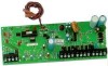
I. GENERAL DESCRIPTION The NX-320E is a microprocessor controlled remote power supply module for the NetworX control panels (refer to Compatibility chart on the back of this manual). This power supply module has three (3) programmable outputs and one (1) dedicated bell output. A maximum of eight (8) - GE NX-320E | Installation Guide - Page 5
the same procedures described above. Once mounted, screw it in securely. Diagram 3: The PC board should slide freely in the grooves of both guides. V. BATTERY CALCULATION TABLE STANDBY TIME 24 hours 48 hours 72 CURRENT 600 mA 1 Amp 1 Amp 1 Amp 1 Amp 1 Amp 1 Amp 1 Amp 1 Amp NX-320E Power Supply 5 - GE NX-320E | Installation Guide - Page 6
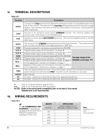
to all devices, including the NX320E is 2500 feet. Connect to the NetworX control panel COMMON terminal. This terminal supplies the common side of the power to the NX-320E board. Connect to control panel AUX POWER + terminal. This terminal supplies power to the NX320E board. This terminal is the - GE NX-320E | Installation Guide - Page 7
VIII. LAYOUT NX-320E Power Supply Recommended: Basler Model BE30614001 120VAC 60Hz 16.5VAC 50VA Class II circuits must be installed using FPL, FPLP, FPLR, CL3, CL3R, or CL3P, or substitute cable permitted by National Electrical Code ANSI/NFPA70 and the Class 2, Class 3 and power-limited fire alarm - GE NX-320E | Installation Guide - Page 8
out from the NX-320E. DS2 Flashes when data is transmitted into the NX-320E. DS3 Flashes during normal operation. DS4 Used for hardware, and will only glow dimly when connected to the NetworX control panel (refer to Compatibility chart on the back of this manual). 8 NX-320E Power Supply - GE NX-320E | Installation Guide - Page 9
, Chime, Exit, Bypass & Cancel LEDS will flash. If the "Go To Program Code" is valid, the "Service" LED will flash and the 5 function LEDs will illuminate steady. You are now in the Program Mode and ready NOTE: These steps are repeated until the last segment is reached. NX-320E Power Supply 9 - GE NX-320E | Installation Guide - Page 10
LED=s are as follows: Zone 1 LED = 1 Zone 2 LED = 2 Zone 3 LED = 4 Zone 4 LED = 8 Zone 5 LED = 16 Zone 7 LED = 64 Zone 6 LED = 32 Zone 8 LED = 128 10 NX-320E Power Supply - GE NX-320E | Installation Guide - Page 11
Dynamic Battery Test Time 14 Any Siren 25 Fire 4 Listen In 15 Steady Siren (temporal) 26 Fire Trouble 5 Line Seizure 16 Any Siren (temporal) 27 Chime 6 Telephone Line Fault 17 Alarm Memory 28 Beeping If set to follow condition, these events will be one second. NX-320E Power Supply 11 - GE NX-320E | Installation Guide - Page 12
should stop time when a code is entered. 4 = "On" for inverted output. 5 = "On" disables output during listen-in (only events 12-16). 6 = Reserved. 7 = Reserved. 8 = Reserved. 12 NX-320E Power Supply - GE NX-320E | Installation Guide - Page 13
Partition 6. 7 = "On" if the event should activate when it occurs in Partition 7. 8 = "On" if the event should activate when it occurs in Partition 8. LOCATIONS 6 & 7 RESERVED NX-320E Power Supply 13 - GE NX-320E | Installation Guide - Page 14
10 segments. Segment 1 corresponds to user 51; Segment 10 corresponds to user 60. The LEDs correspond to outputs A - C (see Table XII:2 on page 14). 14 NX-320E Power Supply - GE NX-320E | Installation Guide - Page 15
. 3 On enables Low Battery reporting If enabled, the power supply module will report Low Battery to the central station. 4 On enables Siren Tamper/Trouble reporting If enabled, the power supply module will report a Siren Tamper to the central station. 5-8 Reserved NX-320E Power Supply 15 - GE NX-320E | Installation Guide - Page 16
"On disables output during listen-in. 6-8 = Reserved. RESERVED DATA _ _ 5 = Partition 5 6 = Partition 6 7 = Partition 7 8 = Partition 8 _ _ 5 = Partition 5 6 = Partition 6 7 = Partition 7 8 = Partition 8 _ _ 5 = Partition 5 6 = Partition 6 7 = Partition 7 8 = Partition 8 16 NX-320E Power Supply - GE NX-320E | Installation Guide - Page 17
#C 3 3 3 3 3 3 3 3 3 3 17 15 Codes 91-99 Output Enable (Circle the numbers to program) User 91 92 93 94 95 96 97 98 99 Output #A 1 1 1 1 1 1 1 1 1 Output #B 2 2 2 2 2 2 2 2 2 Output #C 3 3 3 3 3 3 3 3 3 NX-320E Power Supply 17 - GE NX-320E | Installation Guide - Page 18
to program) 1=On for AC report always sent; Off follows control 2=On enables periodic battery test 3=On enables low battery reporting 4=On enables siren tamper/trouble reporting DEFAULT 5 0 5=Reserved 6=Reserved 7=Reserved 8=Reserved DATA ___ ___ 18 NX-320E Power Supply - GE NX-320E | Installation Guide - Page 19
NOTES NX-320E Power Supply 19 - GE NX-320E | Installation Guide - Page 20
XIV. SPECIFICATIONS NX-320E DIMENSIONS CURRENT DRAW AUXILIARY POWER BATTERY OPERATING TEMPERATURE SHIPPING WEIGHT 2.0" Wide 9.0" High 4.0" Deep AC Input: 120V, 60Hz, 650mA 10 mA Standby 16.5 VAC 50 VA Transformer Limited to 2.5 Amps with
-
 1
1 -
 2
2 -
 3
3 -
 4
4 -
 5
5 -
 6
6 -
 7
7 -
8
-
9
-
10
-
11
-
12
-
13
-
14
-
15
-
16
-
17
-
18
-
19
-
20
 |
 |

NetworX
™
Series
NX-320E REMOTE POWER SUPPLY
Installation and Startup