GE NX548E Installation Instructions
GE NX548E - Secuirity NetworX 48-Zone Wireless Receiver Manual
 |
UPC - 782136713930
View all GE NX548E manuals
Add to My Manuals
Save this manual to your list of manuals |
GE NX548E manual content summary:
- GE NX548E | Installation Instructions - Page 1
NX-548E Receiver Installation Instructions 466-2225B July 2006 Copyright © 2006, GE Security Inc. Contents Introduction 1 Internal mounting 1 External mounting 2 Wiring 3 DIP switch settings 3 Power up 3 Programming 4 Testing and troubleshooting 6 Programming settings table 7 Supported - GE NX548E | Installation Instructions - Page 2
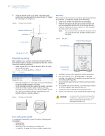
2 NetworX NX-548E Receiver Installation Instructions 6. Align the bottom of the circuit board in the edge guide standoff and twist the standoff into place (Figure 4). Tighten the mounting screw (Figure 2). Figure 4. Installing the circuit board Antenna shroud Enclosure Mounting The module can be - GE NX548E | Installation Instructions - Page 3
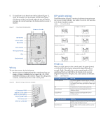
on the control panel. Figure 8. Receiver wiring connections and LEDs + 12 (to panel POS) GND (to panel COM) DATA (to panel DATA) Green (power) LED Red (data) LED Red (not used) LED DIP switch settings The DIP switches (Figure 7) on the circuit board are used to set the receiver module number. Use - GE NX548E | Installation Instructions - Page 4
4 NetworX NX-548E Receiver Installation Instructions Programming This section describes how to program the units. Programming guidelines Use the following programming guidelines: • NX-4 and NX-6 control panels can have receivers added with zones that overlap those contained in the control panel. - GE NX548E | Installation Instructions - Page 5
the service light flashes and the five function lights change from flashing to on steady. 3. Enter the DIP switch setting module number for the receiver and press #. On LED touchpads, the Armed LED turns on to indicate the control panel is waiting for a programming location entry. 4. Enter the zone - GE NX548E | Installation Instructions - Page 6
6 NetworX NX-548E Receiver Installation Instructions Transmitter supervision windows LCD touchpads will display instructions when accomplishing tasks. To change the transmitter supervision windows, do the following: 1. Enter * 8 at the keypad. On LED touchpads, the five func- tion lights start - GE NX548E | Installation Instructions - Page 7
Partition 5 keyfob Partition 6 keyfob Partition 7 keyfob Partition 8 keyfob Table 5. Programming settings (continued) Location Segment 1 Zone _____ Assigned to module #_____. RM HE P 1 - Enable sensor 2 - Supervised 3 - Fire supervision 4 - Input option 1 5 - Input option 2 6 - 80-bit device - GE NX548E | Installation Instructions - Page 8
8 NetworX NX-548E Receiver Installation Instructions Table 5. Programming settings (continued) Location Segment 1 Zone _____ Assigned to module #_____. RM HE P 1 - Enable sensor 2 - Supervised 3 - Fire supervision 4 - Input option 1 5 - Input option 2 6 - 80-bit device 7 - Input option 3 8 - - GE NX548E | Installation Instructions - Page 9
Partition 5 keyfob Partition 6 keyfob Partition 7 keyfob Partition 8 keyfob Table 5. Programming settings (continued) Location Segment 1 Zone _____ Assigned to module #_____. RM HE P 1 - Enable sensor 2 - Supervised 3 - Fire supervision 4 - Input option 1 5 - Input option 2 6 - 80-bit device - GE NX548E | Installation Instructions - Page 10
10 NetworX NX-548E Receiver Installation Instructions Table 5. Programming settings (continued) Location Segment 1 Zone _____ Assigned to module #_____. RM HE P 1 - Enable sensor 2 - Supervised 3 - Fire supervision 4 - Input option 1 5 - Input option 2 6 - 80-bit device 7 - Input option 3 8 - - GE NX548E | Installation Instructions - Page 11
Table 5. Programming settings (continued) Location Segment 1 200 Number of rounds received from last transmitter learned See Testing and troubleshooting on page 6. None Segment 2 None 11 Supported devices For 80-bit devices, Feature 6 must be on for Segment 1 on zone location. For 63-bit - GE NX548E | Installation Instructions - Page 12
NetworX NX-548E Receiver Installation Instructions Specifications Compatibility Frequency Wireless range Required power Current draw Operating temperature Storage temperature Max. relative humidity Dimensions Listings UL CUL NX-4, NX-6, NX-8, NX-8E control panels . Technical support Toll-free
-
 1
1 -
 2
2 -
 3
3 -
 4
4 -
 5
5 -
 6
6 -
 7
7 -
8
-
9
-
10
-
11
-
12
 |
 |
466-2225B
July 2006
Copyright © 2006, GE Security Inc.
NetworX NX-548E Receiver
Installation Instructions
Contents
Introduction
. . . . . . . . . . . . . . . . . . . . . . . . . . . . . . . . . . . . . 1
Internal mounting
. . . . . . . . . . . . . . . . . . . . . . . . . . . . . . . . 1
External mounting
. . . . . . . . . . . . . . . . . . . . . . . . . . . . . . . . 2
Wiring
. . . . . . . . . . . . . . . . . . . . . . . . . . . . . . . . . . . . . . . . . 3
DIP switch settings
. . . . . . . . . . . . . . . . . . . . . . . . . . . . . . . 3
Power up
. . . . . . . . . . . . . . . . . . . . . . . . . . . . . . . . . . . . . . . 3
Programming
. . . . . . . . . . . . . . . . . . . . . . . . . . . . . . . . . . . 4
Testing and troubleshooting
. . . . . . . . . . . . . . . . . . . . . . . . 6
Programming settings table
. . . . . . . . . . . . . . . . . . . . . . . . 7
Supported devices
. . . . . . . . . . . . . . . . . . . . . . . . . . . . . . . 11
Specifications
. . . . . . . . . . . . . . . . . . . . . . . . . . . . . . . . . . 12
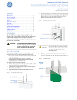
Introduction
The NX-548E Receiver adds wireless capabilities to the
NetworX line of control panels. Adding a receiver makes these
control panels compatible with NX wireless transmitters.
Only three wire connections are required for power and commu-
nication to the control panel.
Internal mounting
For internal mounting, mount the receiver inside the control
panel enclosure. Use the following installation guidelines:
•
Leave at least 10 in. (25 cm) above the control panel for the
receiver’s antennas.
•
Avoid areas that expose the receiver to moisture.
•
Avoid areas with excessive metal or electrical wiring,
including furnaces and utility rooms.
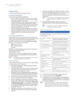
To mount the receiver, do the following:
1.
Remove the appropriate knockouts on the top of the control
panel enclosure for the antenna shrouds.
2.
Assemble the antenna shrouds and fit the black O-rings to
the bottom of each shroud.
3.
Insert the shrouds into the knockout holes (
Figure 1
).
Figure 1.
Installing the antenna shrouds
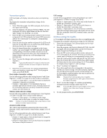
4.
Use the mounting screw provided to loosely install the edge
guide standoff in the lower mounting hole in the appropriate
space to the left of the control panel (
Figure 2
). Do not
tighten the mounting screw down at this time.
Figure 2.
Installing the edge guide standoff
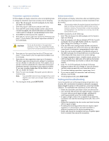
5.
Slide the printed circuit board into the antennae shroud
slots, after inserting wires into antennae shrouds (
Figure 3
).
Figure 3.
Anntennae shrouds
WA
WARNING:
To avoid possible equipment damage
or personal injury, remove power from
the control panel before making any
wiring connections to the receiver.
Antenna shroud
O-ring
Knockout hole
Enclosure top
CAUTION
You must be free of static electricity before
handling circuit boards. Touch a bare metal
surface or wear a grounding strap to
discharge yourself.
Mounting screw
Edge guide standoff
Circuit
Antennae
Enclosure
shrouds
board