GE PGS968SEPSS Installation Instructions
GE PGS968SEPSS Manual
 |
UPC - 084691199755
View all GE PGS968SEPSS manuals
Add to My Manuals
Save this manual to your list of manuals |
GE PGS968SEPSS manual content summary:
- GE PGS968SEPSS | Installation Instructions - Page 1
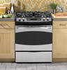
Installation Instructions 30" Gas Self-Clean Slide-In Range Questions? Call 800.GE.CARES (800.432.2737) or visit our Website at: GEAppliances.com In Canada, call 1.800.561.3344 or visit our Website at: www.GEAppliances.ca BEFORE YOU BEGIN Read these instructions completely and carefully. • - GE PGS968SEPSS | Installation Instructions - Page 2
guides. Push the drawer range Large head and cap B. Make sure the slot in the burner head is positioned over the electrode (on some models electrical power. A. Turn on gas. B. Push and turn a burner valve to the LITE position. • The burner valve should light when gas , call GE Service. 1/2" to
-
 1
1 -
 2
2
 |
 |
PREPARE THE OPENING (CONT.)
2
PREPARE THE OPENING (FOR INDOOR USE ONLY)
If the countertop area is not flat, excess tension may be applied to the cooktop causing damage and voiding
the warranty. Make sure the wall covering, countertop, flooring and cabinets around the range can withstand
the heat (up to 200°F [93.3°C]) generated by the range.
A
. Allow 30
" (76.2 cm)
minimum clearance between burners and bottom of unprotected wood or metal
cabinet, or allow a 24
" (61 cm)
minimum when bottom of wood or metal cabinet is protected by no less
than 1/4
" (6.4 mm)
thick flame-retardant millboard covered with no less than No. 28 MSG sheet metal
(.015
" [.38 mm]
thick), .015
" (.38 mm)
thick stainless steel, .025
" (0.64 mm)
aluminum or .020
"
(0.5 mm)
copper.
B
. Side wall clearance requirement:
6
" (15.2 cm)
clearance for models JGSP28, JGS905, JGS968 and PGS968
9½
" (24.1 cm)
clearance for models PGS908 and PGS975
To reduce the risk of burns or fire when reaching over burners, cabinet storage space above the cooktop
should be avoided. If cabinet storage space is to be provided above the cooktop, the risk can be reduced
by installing a range hood that projects at least 5
" (12.7 cm)
beyond the front of the cabinets. Cabinets
installed above the cooktop must be no deeper than 13
" (33 cm)
.
Seal any openings in the wall behind the range and the floor under the range.
2
If you did not receive an anti-tip
bracket with your purchase, call
1.800.626.8774 to receive one
at no cost. (In Canada, call
1.800.561.3344.) For installation
instructions of the bracket, visit:
www.GEAppliances.com.
(In Canada, www.GEAppliances.ca.)
Installation Instructions
30" Gas Self-Clean Slide-In Range
Questions?
Call 800.GE.CARES (800.432.2737) or visit our Website at: GEAppliances.com
In Canada, call 1.800.561.3344 or visit our Website at: www.GEAppliances.ca
31-10675
06-09
JR
BEFORE YOU BEGIN
Read these instructions completely and carefully.
•
IMPORTANT
–
Save these
instructions for local inspector’s use.
•
IMPORTANT
–
Observe all governing
codes and ordinances.
•
Note to Installer –
Leave these
instructions with appliance after installation
is complete.
•
Note to Consumer –
Keep these
instructions for future reference.
•
Note to Servicer –
The electrical diagram
is in an envelope attached to the back
of the range.
•
Proper installation is the responsibility
of the installer. Product failure due to
improper installation is not covered under
the Warranty.
•
Installation of the range must conform
with local codes or, in the absence of local
codes, with the National Fuel Gas, ANSI
Z223.1/NFPA 54, latest edition. In Canada,
installation must conform with the current
Natural Gas Installation Code, CAN/CSA-
B149.1 or the current Propane Installation
Code, CAN/CSA-B149.2, and with local
codes where applicable. This range has
been design-certified by Underwriter’s
Laboratories for use in the United States
and Canada.
WARNING:
Fire and Explosion Hazard:
If the information in the manual is not followed exactly, a fire or explosion may result causing
property damage, personal injury, or death.
•
If you smell gas:
– Open windows
– Don’t touch electrical switches.
– Extinguish any open flame.
– Immediately call your gas supplier.
•
Do not store or use combustible materials, gasoline or other flammable vapors and liquids
in the vicinity of this or any other appliance.
•
Installation and service must be performed by a qualified installer, service agency or the gas
supplier.
•
Remove all packing material and literature from oven before connecting gas and electrical
supply to the range.
IN THE COMMONWEALTH OF MASSACHUSETTS:
•
This product must be installed by a licensed plumber or gas fitter.
•
When using ball-type gas shut-off valves, they shall be the T-handle type.
•
A flexible gas connector, when used, must not exceed 3 feet (91.4 cm).
Anti-Tip Bracket
Kit Included
WARNING:
Electrical Shock Hazard:
This appliance must be properly grounded in accordance with local codes or, in the absence of local codes,
in accordance with the National Electrical Code (ANSI/NFPA 70, latest edition).
In Canada, electrical
grounding must be in accordance with the current CSA C22.1 Canadian Electrical Code Part 1 and/or local
codes. See the Electrical Requirements section.
MATERIALS YOU MAY NEED
TOOLS YOU WILL NEED
CSA-Approved Flexible Gas Line 3/8" Min. ID, 1/2" NPT Connection
Shut-Off Valve
Joint Sealant
Pipe Fittings
Drill with 1/8" Bit
Safety Glasses
Adjustable Wrench
Pipe Wrench
Level
Tape Measure
Pliers
1/4" Nut Driver
Phillips-Head Screwdriver
Flat-Blade Screwdriver
PRESSURE TEST INFORMATION
The maximum allowable supply pressure for the regulator is 14" W.C. The minimum supply
pressure needed to check the regulator setting is 7" W.C. for natural gas and 10" W.C. for LP
gas.
WARNING:
The range and its individual shut-off valve must be
disconnected from the gas supply piping system during any pressure testing of the gas
supply system at test pressures of more than 1/2 psig (pounds per square inch gauge).
The range must be isolated from the gas supply piping system by closing its individual
shut-off valve during any pressure testing of the gas supply system at test pressures
equal to or greater than 1/2 psig. NOTE: 1/2 psig = 13.855" w.c.
REMOVE PACKAGING MATERIALS
Failure to remove packaging materials could result in
damage to the appliance. Remove all packing parts from
oven, racks and drawer. Also, remove protective film and
labels on the door, cooktop and backguard. However,
do not remove protective channel from sides of glass
cooktop, if applicable, until later in installation.
Move Range Indoors in Front of Cabinet Opening:
Do not use hand trucks when moving the unpacked range,
as damage to the cooktop may occur.
Protect the Kitchen Floor:
Flatten and place a piece of the shipping carton in front
of the installation location to protect the flooring.
1
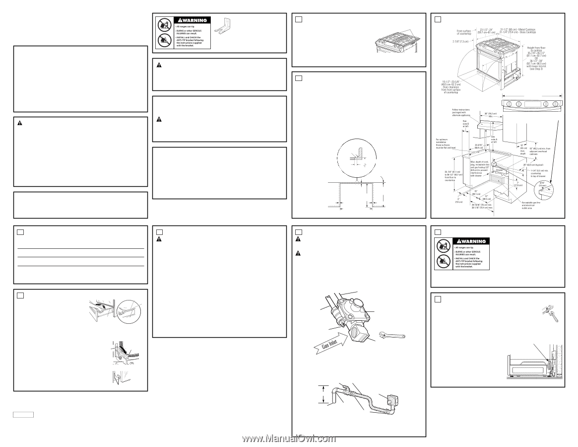
Protective Channels
31-1/8" (79.1 cm)
If the control panel measures 31-1/8" (79.1 cm) like in
the illustration AND if the countertop has a raised edge,
shave raised edge to clear the control panel, as shown
below.
1/4" (6.4 mm) min.
flat
25" (63.5 cm)
typically
9/16" (14.3 mm) min. flat
23-3/16" (58.9 cm)
typically
9/16" (14.3 mm)
min. flat
Wall
29-15/16"–30-1/16"
(76 cm–76.5 cm)
smooth cut
R
1/4" (6.4 mm)
36" (91.4 cm)
Flat area
Front
Back
Floor
PREPARE THE RANGE
4
DOOR REMOVAL (optional)
Door removal is not a requirement for installation of the product but is an added convenience.
To remove the door:
A.
Open the oven door as far as it will go.
B.
Push both hinge locks down toward the door frame to the
unlocked position. This may require a flat-blade screwdriver.
DO NOT LIFT THE DOOR BY THE HANDLE!
C.
Place hands on both sides of the door, and close the oven door
to the removal position. (Approximately 1"–2" [2.5 cm–5.1 cm]
from the closed position.)
D.
Lift door up and out until the hinge arms clear the slots.
NOTE:
The oven door is very heavy. Be sure you have a firm
grip before lifting the oven door off the hinges. Use caution once
the door is removed. Do not lay the door on its handle. This
could cause dents or scratches.
Hinge
unlocked
position
Hinge
slot
Hinge
arm
STORAGE DRAWER REMOVAL
A.
Pull drawer out until it stops.
B.
Lift front of drawer until the stops clear the guide.
C.
Pull forward and remove the drawer.
Rail
Guide
Stop
Stop
ALTERNATE INSTALLATION/ CONSTRUCTION KITS
3
Backguard Kit:
Used when replacing a free-standing range with a slide-in range. Adds a decorative
backguard to the rear of the range. This kit can only be used when the opening in the countertop is
25" (63.5 cm) deep.
Maintop Filler Kit:
Adds a filler strip to the rear of the range. This kit can only be used when
the opening in the countertop is 25" (63.5 cm) deep. This kit cannot be used with a backguard kit.
Body Side Kit:
Used when cabinets are absent on one side of the range. Contains a color-matched
side panel which can be used to create a finished appearance on either side of the range.
Lower Trim Kit:
Contains a color-matched toe kick and extra-long leveling legs. Designed to be used
when the range needs to be raised higher than 36-1/2" (92.7 cm) to 38" (96.5 cm).
To order accessory kits, call 1.866.775.4557, or visit www.GEAppliances.com.
Hinge clears slot
ELECTRICAL REQUIREMENTS
WARNING:
This appliance must be properly grounded
.
IMPORTANT:
This appliance must be electrically grounded in accordance with local codes or,
in the absence of local codes, with the National Electrical Code, ANSI/NFPA 70 or Canadian
Electrical Code, CSA C22.1.
This appliance must be supplied with 120 VAC / 60 Hz power. It must be connected
to a properly grounded branch circuit, protected by a 15-amp or 20-amp circuit breaker or fuse.
We recommend that a separate circuit serving only this appliance be provided.
The power cord of this appliance is equipped with a three-prong (grounding) plug which mates
with a standard three-prong grounding wall receptacle. The customer should have the wall
receptacle checked by a qualified electrician to make sure the receptacle is properly grounded.
Where a standard two-prong wall receptacle is encountered, it is the personal responsibility and
obligation of the customer to have it replaced with a properly grounded three-prong wall
receptacle.
Do not, under any circumstances, cut or remove the third prong (ground) from the
power cord.
Because of potential safety hazards under certain conditions, we strongly recommend against
the use of an extension cord. However, if you still elect to use an extension cord, it is absolutely
necessary that it is a UL-listed 3-wire grounding-type appliance extension cord, and that the
current-carrying rating of the cord in amperes is equivalent to, or greater than, the branch
circuit rating.
Installation of this product in a mobile home must conform with the Manufactured Home
Construction and Safety Standard, Title 24 CFR, Part 3280. If this standard does not apply,
you must follow the standard for the Manufactured Home Installations, ANSI A225.1 and
Manufactured Home Installations, Sites and Communities and ANSI/NFPA 501A or with
local codes.
5
MAKE GAS CONNECTIONS
WARNING:
Never reuse old flexible connectors. The use of old flexible
connectors can cause gas leaks and personal injury. Always use new flexible connectors
when installing a gas appliance.
WARNING:
Do not use a flame to check for gas leaks. Use liquid leak
detector at all joints and connections to check for leaks in the system.
A.
Install a manual shut-off valve in the gas supply line in an easily accessible location.
B.
Know how and where to shut off the gas supply to the range.
C.
Shut off gas supply before removing an old range. Leave it off until hookup of new range
is finished.
D.
Because solid pipe restricts moving the range, we recommend use of a C.S.A.-certified
flexible metal appliance connector.
E.
Before making gas connections, make sure that the oven shut-off lever (visible at the back
of range) is in the open position.
F.
To prevent gas leaks, put a pipe joint sealant or Teflon
®
tape on all male threads.
NOTE:
Make sure sealant or tape is compatible with Natural and LP gases.
G.
Install 1/2" flare union adapter to the 1/2" NPT elbow on pressure regulator.
H.
Connect flexible gas line to flare union.
I.
Move range into approximate position and connect flexible gas line to gas supply line with
proper flare union adapter.
J.
When you are finished making connections, be sure that all range knobs are turned to OFF
before you open the main gas supply valve.
K. CHECK FOR LEAKS.
Turn the gas supply on and use a liquid leak detector (soap solution)
at all joints and connections to check for leaks.
Do not use open flame to look for leaks.
Be sure all leaks are stopped before lighting burners.
6
Gas supply to top
burners
Pressure regulator
as seen from front
of range
Gas
supply
to oven
Oven shut-off lever
shown in the open
position
NOTE:
When screwing
on the flare union adapter,
hold the gas inlet firmly
with a wrench.
Pressure
regulator
Gas supply
line
90° street
elbow
Shut-off valve
Flexible gas line
7" (17.8 cm) Max.
Flare union
ANTI-TIP DEVICE INSTALLATION
To reduce the risk of tipping the range, the range must
be secured by a properly installed anti-tip bracket. See
installation instructions shipped with the bracket for
complete details before attempting to install.
To check if the bracket is installed and engaged
properly, remove the storage drawer or kick panel and
look underneath the range to see that the leveling leg
is engaged in the bracket. On models without a storage
drawer or kick panel, carefully tip the range forward.
The bracket should stop the range within 4 inches
(10.2 cm). If it does not, the bracket must be reinstalled. If the range is pulled from the wall for any
reason, always repeat this procedure to verify the range is properly secured by the anti-tip bracket.
Never completely remove the leveling legs or the range will not be secured to the anti-tip device
properly.
7
SLIDE RANGE INTO OPENING
A.
Position the range in front of the cabinet opening. Make sure that the cooktop
that overhangs the countertop clears the countertop. If necessary, raise the unit
by lowering the leveling legs.
B.
Push while lifting the range into the opening until the range is within 2" (5.1 cm)
of engaging the anti-tip bracket. Remove the protective channel from the side
of glass (if provided).
C.
Using the adjustable pliers or wrench, carefully screw in the back leveling legs until the cooktop
overhang touches the countertop. Then carefully screw in the front two leveling legs until the
cooktop overhang touches the countertop.
D.
Carefully push the range into the opening until the unit is
fully seated into the cabinet. The back cooktop overhang
should cover the cutout opening. Plug the range cord
into the receptacle. Locate the flexible gas line in the
back of the range in a manner that it will not touch or
be moved by the drawer.
8
Position gas line so that there is no
interference with the storage drawer
STORAGE DRAWER
R
E
A
R
W
A
L
L
SIDE VIEW
31-10737 = French version
31-10738 = Spanish version