GE PS968SPSS Installation Instructions
GE PS968SPSS - Profile - 30" Electric Range Manual
 |
UPC - 084691197546
View all GE PS968SPSS manuals
Add to My Manuals
Save this manual to your list of manuals |
GE PS968SPSS manual content summary:
- GE PS968SPSS | Installation Instructions - Page 1
Installation Instructions 30" Electric Slide-In Ranges Questions? Call 1.800.GE.CARES (1.800.432.2737) or visit www.geappliances.com In Canada, call 1.800.561.3344 or visit www.geappliances.ca BEFORE YOU BEGIN Read these instructions completely and carefully. • IMPORTANT - Save these instructions - GE PS968SPSS | Installation Instructions - Page 2
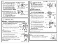
to keep the edge from damaging the cable. Rating plate The rating plate is located on the oven frame or on the side of the drawer frame. 6 POWER CORD AND CONDUIT INSTALLA- TION A. Remove wire cover (on the back of range) by removing screws using a 1/4" nut driver. Do not discard these screws - GE PS968SPSS | Installation Instructions - Page 3
may be used but it must be rated for the correct amperage and voltage. PROCEED TO STEP 9. Conduit 8 4-WIRE INSTALLATION Before-Power Cord and Conduit be used but it must be rated for the correct amperage and voltage. 9 REPLACE THE WIRE COVER Replace wire cover on range back by sliding its left - GE PS968SPSS | Installation Instructions - Page 4
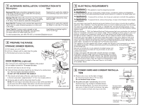
See installation instructions shipped with the bracket for complete details before attempting to install. To check if the bracket is installed and engaged properly, remove the storage drawer or kick panel and look underneath the range to see that the leveling leg is engaged in the bracket. On models
-
 1
1 -
 2
2 -
 3
3 -
 4
4
 |
 |
BEFORE YOU BEGIN
Read these instructions completely and
carefully.
•
IMPORTANT —
Save these
instructions for local inspector’s use.
•
IMPORTANT —
Observe all gov-
erning codes and ordinances.
•
Note to Installer –
Be sure to leave these
instructions with Consumer.
•
Note to Consumer –
Keep these instruc-
tions for future reference.
•
Skill level –
Installation of this appliance
requires basic mechanical skills
and advanced electrical skills.
•
Proper installation is the responsibility
of the installer.
•
Product failure due to improper installation
is not covered under Warranty.
Installation Instructions
30
"
Electric Slide-In Ranges
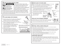
FOR YOUR SAFETY:
If you did not receive an anti-tip bracket with your purchase,
call 1.800.626.8774 to receive one at no cost. (In Canada,
call 1.800.561.3344.) For installation instructions of the bracket,
visit: www.geappliances.com. (In Canada, www.geappliances.ca.)
Anti-Tip Bracket
Kit Included
Questions?
Call 1.800.GE.CARES (1.800.432.2737) or visit www.geappliances.com
In Canada, call 1.800.561.3344 or visit www.geappliances.ca
WARNING
—
Before
beginning the installation, switch
power off at service panel and
lock the service disconnecting
means to prevent power from
being switched on accidentally.
When the service disconnecting
means cannot be locked, secure-
ly fasten a prominent warning
device, such as a tag,
to the service panel.
MATERIALS YOU MAY NEED
TOOLS YOU WILL NEED
(UL Listed 40 AMP)
4-Wire Cord 4' long
OR
3-Wire Cord 4' long
Squeeze Connector
(For Conduit
Installations Only)
REMOVE PACKAGING MATERIALS:
Failure to remove packaging
materials could result in damage to the appliance. Remove all packing parts from oven,
racks, heating elements and drawer. Also, remove protective film and labels on the door,
cooktop
(do not remove side protection on glass cooktops)
and backguard.
Do not remove protective channel from sides of glass cooktop, if applicable, until later
in installation.
1
Drill with 1/8" Bit
Safety Glasses
Adjustable Wrench
Level
Tin Snips
Tape Measure
Pliers
1/4" Nut Driver
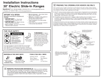
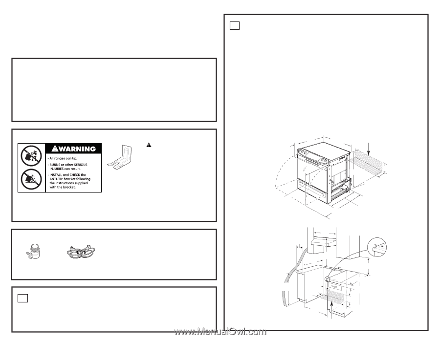
PREPARE THE OPENING (FOR INDOOR USE ONLY)
If the countertop area is not flat, excess tension may be applied to the glass cooktop causing breakage
and voiding the warranty. Make sure the wall covering, countertop, flooring and cabinets around the range
can withstand the heat (up to 200˚F) generated by the range.
A
. Allow 30
"
minimum clearance between surface units and bottom of unprotected wood or metal cabinet,
or allow a 24
"
minimum when bottom of wood or metal cabinet is protected by no less then 1/4
"
thick
flame retardant millboard covered with no less than No. 28 MSG sheet metal (.015
"
thick), .015
"
thick
stainless steel, .025
"
aluminum or .020
"
copper.
B
. This appliance has been approved for 0
"
spacing to adjacent surfaces above the cooktop. However,
a minimum 6
"
spacing to surfaces less than 15
"
above the cooktop and adjacent cabinetry
is recommended to reduce exposure to steam, grease splatter and heat. Allow 1/4
"
minimum clearance
at the back wall.
To reduce the risk of burns or fire when reaching over hot surface elements, cabinet storage space above
the cooktop should be avoided. If cabinet storage space is to be provided above the cooktop, the risk can
be reduced by installing a range hood that projects at least 5
"
beyond the front of the cabinets. Cabinets
installed above the cooktop must be no deeper than 13
"
.
2
31-1/4"
2-7/8"
To front
surface of
countertop
25-3/4"
(excluding
handle)
Height from floor to range top
35-7/8"–36-1/2"
OR
36-1/2"–38" with lower trim
slide-in kit (see Step 3)
Acceptable electrical outlet area.
Orient electrical receptacle so
the length is parallel to floor.
46-3/8"
36-1/4"
7-1/2"
20-5/8"
Door clearance from
front surface of
countertop
24"
30"
Min.
9/16"
15"
Min.
7-1/2"
2-1/2"
23-3/16"
Acceptable electrical
outlet area
25"
29-15/16"–30-1/16"
For Profile models only, if
countertop has a raised edge,
shave raised edge to clear
31-1/8" wide control panel.
1/4" Min. Flat
35-7/8"–38" from
Floor to countertop
2-1/2"
B
A
1-1/4" Min, from countertop
to top of cabinet drawer.
4"
4"
NOTE: Use a 4' power cord to prevent
interference with the storage drawer.
Power cords 4-1/2' to 6' long may have
to be dressed to allow for proper draw-
er closing.