GE PTDS650EMWT Installation Instructions
GE PTDS650EMWT Manual
 |
UPC - 084691227069
View all GE PTDS650EMWT manuals
Add to My Manuals
Save this manual to your list of manuals |
GE PTDS650EMWT manual content summary:
- GE PTDS650EMWT | Installation Instructions - Page 1
location where it could be exposed to water and or weather. • Save these instructions. (Installers: Be sure to leave these instructions with the customer). NOTE: Installation and service of this dryer requires basic mechanical and electrical skills. It is your responsibility to contact a qualified - GE PTDS650EMWT | Installation Instructions - Page 2
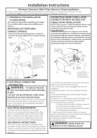
single phase, 120/240V or 120/208V, 60Hz, 30 amp circuit is required. If the electric supply does not meet the above specifications, then call a licensed electrician. GROUNDING INSTRUCTIONS This dryer must be connected to a grounded metal, permanent wiring system, or an equipment-grounding conductor - GE PTDS650EMWT | Installation Instructions - Page 3
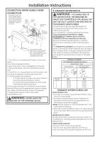
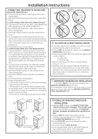
LENGTH TABLE. Using exhaust longer than specified length will: • Increase the drying times and the energy cost. • Reduce the dryer life. • Accumulate lint, creating a potential fire hazard. The correct exhaust installation is YOUR RESPONSIBILITY. Problems due to incorrect installation are not - GE PTDS650EMWT | Installation Instructions - Page 4
home exhaust duct . • Use only 4" rigid metal or UL-listed flexible metal (semi-rigid or foil-type) duct to connect the dryer to the home exhaust duct. It must be installed in accordance with the instructions found in "Connecting The Dryer To House Vent" on page 5 of this manual. • Do not terminate - GE PTDS650EMWT | Installation Instructions - Page 5
of 60 sq. in. of open area equally distributed. If the closet contains both a washer and a dryer, doors must contain a minimum of 120 sq. in. of open area equally distributed. 7 BATHROOM OR BEDROOM INSTALLATION • The dryer MUST be vented to the outdoors. See EXHAUST INFORMATION section 3 & 4. • The - GE PTDS650EMWT | Installation Instructions - Page 6
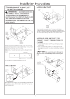
Installation Instructions 9 DRYER EXHAUST TO RIGHT, LEFT OR BOTTOM CABINET WARNING - BEFORE PERFORMING THIS EXHAUST INSTALLATION, BE SURE TO DISCONNECT THE DRYER FROM ITS ELECTRICAL shortened duct is aligned with the tab in the base. Use the screw saved previously to secure the duct in place through - GE PTDS650EMWT | Installation Instructions - Page 7
Installation Instructions • Apply duct tape as shown on the joint between the dryer internal duct and the elbow. DUCT TAPE CAUTION: Internal duct joints must be secured with tape, otherwise they may separate and cause a safety hazard. ADDING ELBOW FOR EXHAUST THROUGH BOTTOM OF CABINET • - GE PTDS650EMWT | Installation Instructions - Page 8
Installation Instructions 11 CONNECTING INLET HOSES (on some models) To produce steam, the dryer must connect to the cold water supply. Since the washer must also connect to the cold water, a "Y" connector is inserted to allow both inlet hoses to make that connection at the same time. NOTE: Use the
-
 1
1 -
 2
2 -
 3
3 -
 4
4 -
 5
5 -
 6
6 -
 7
7 -
8
 |
 |

WARNING
RISK OF FIRE
• To reduce the risk of severe injury or death, follow all installation
instructions.
• Clothes dryer installation must be performed by a qualified installer.
• Install the clothes dryer according to these instructions and in
accordance with local codes.
• This dryer must be exhausted to the outdoors.
• Use only 4” rigid metal ducting for exhausting the clothes dryer to the
outdoors.
•
DO NOT
install a clothes dryer with flexible plastic ducting materials.
If flexible metal (semi-rigid or foil-type) duct is installed, it must be
UL listed and installed in accordance with the instructions found in
“Connecting The Dryer To House Vent” on page 5 of this manual.
Flexible venting materials are known to collapse, be easily crushed,
and trap lint. These conditions will obstruct dryer airflow and increase
the risk of fire.
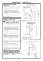
• Do not install or store this appliance in any location where it could be
exposed to water and or weather.
• Save these instructions. (Installers: Be sure to leave these instructions
with the customer).
NOTE:
Installation and service of this dryer requires basic
mechanical and electrical skills. It is your responsibility to
contact a qualified installer to make the electrical connections.
Installation
Instructions
Electric Dryer
05
Questions on Installation? Call: 1-800-GECARES (US)
or Visit our Web site at:
www.GEAppliances.com (US)
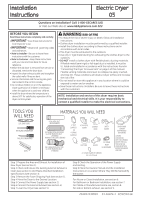
BEFORE YOU BEGIN
Read these instructions completely and carefully.
•
IMPORTANT-
Save these instructions for
local inspector’s use.
•
IMPORTANT-
Observe all
governing codes
and ordinances.
•
Note to Installer -
Be sure to leave these
instructions with the customer.
•
Note to Customer -
Keep these instructions
with your Use and Care Book for future
reference.
• Before the old dryer is removed from service or
discarded, remove the dryer door.
• Inspect the dryer exhaust outlet and straighten
the outlet walls if they are bent.
• Service information and the wiring dia-gram
are located in the control console.
• Do not allow children on or in the appliance.
Close supervision of children is necessary
when the appliance is used near children.
• Install the dryer where the temperature is
above 50°F for satisfactory operation of the
dryer control system.
TOOLS YOU
WILL NEED
PHILLIPS SCREWDRIVER
SLIP JOINT PLIERS
LEVEL
FLAT BLADE SCREWDRIVER
MATERIALS YOU WILL NEED
GLOVES
SAFETY
GLASSES
DRYER POWER
CORD KIT
(NOT PROVIDED
WITH DRYER)
4" DUCT
CLAMPS (2)
OR
4" SPRING
CLAMPS (2)
EXHAUST
HOOD
3/4" STRAIN
RELIEF
UL RECOGNIZED
4" DIA. METAL
ELBOW
DIA. FLEXIBLE METAL (SEMI-RIGID)
UL LISTED TRANSITION DUCT
(IF NEEDED)
WX08X10077 (INCLUDES 2 ELBOWS)
4" DIA. METAL DUCT
(RECOMMENDED)
DIA. FLEXIBLE METAL (FOIL TYPE)
UL LISTED TRANSITION DUCT
(IF NEEDED.)
DUCT TAPE
UL RATED
120/240V,30A
WITH 3 OR 4 PRONGS.
IDENTIFY THE PLUG
TYPE AS PER THE
HOUSE RECEPTACLE
BEFORE PURCHASING
LINE CORD.
4” COVER PLATE (IF NEEDED
(KIT WE1M454)
234D1113P001
31-16224-1
07/07/10 GE
Step 1 Prepare the Area and Exhaust for Installation of
New Dryer (see section 1).
Step 2 Check and Ensure the Existing External Exhaust is
Clean (see section 1) and Meets Attached Installation
Specifications (see section 3).
Step 3 Remove the Foam Shipping Pads (see section 1).
Step 4 Move the Dryer to the Desired Location.
Step 5 Connect the Power Supply (see section 2).
Step 6 Connect the External Exhaust (see section 4).
Step 7 Level Your Dryer (see section 5).
Step 8 Check the Operation of the Power Supply
and Venting.
Step 9 Place the Owners Manual and the Installation
Instructions in a Location Where They Will Be Noticed By
the Owner.
For Alcove or Closet Installation, see section 6.
For Bathroom or Bedroom Installation, see section 7.
For Mobile or Manufactured Home see, section 8.
For side or bottom exhaust, see section 9.