Genie ChainLift 800 Owner's Manual
Genie ChainLift 800 Manual
 |
View all Genie ChainLift 800 manuals
Add to My Manuals
Save this manual to your list of manuals |
Genie ChainLift 800 manual content summary:
- Genie ChainLift 800 | Owner's Manual - Page 1
. © GMI Holdings, Inc. d/b/a The Genie Company PN# 37026500123, 5/15/2009 ALWAYS AT YOUR COMMAND Models 2022/2024/2042 GARAGE DOOR OPENERS Includes: 2-Bulb Light System Wall Console Includes INTELLICODE® Remote Control Safe-T-Beam® System must be installed to close door. For use only with sectional - Genie ChainLift 800 | Owner's Manual - Page 2
, repair or adjust springs or anything to which door spring parts are fastened, such as, wood blocks, steel brackets, cables or other like items. Installations, repairs and adjustments must be done by a trained door system technician using proper tools and instructions. PN# 37026500123 05/15/2009 - Genie ChainLift 800 | Owner's Manual - Page 3
26 TROUBLESHOOTING GUIDE - OPENER 27 TROUBLESHOOTING GUIDE - POWER HEAD LED . . . . . 28 TRANSMITTER COMPLIANCE STATEMENT 29 WARRANTY 30 *Opener MUST be installed with the included Wall Control. **Safe-T-Beam® Safety Reverse System MUST be installed to close door. OPENER FEATURES INTELLICODE - Genie ChainLift 800 | Owner's Manual - Page 4
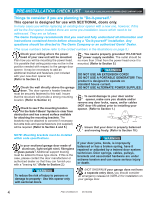
an existing door opener with a new one, however, if this will be the first opener installed there are some pre-installation issues which need to be addressed. They are as follows: The Genie Company recommends that you read and fully understand all information and instructions contained herein - Genie ChainLift 800 | Owner's Manual - Page 5
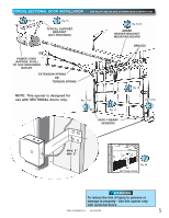
SECTIONAL DOOR INSTALLATION 5 Pg. 19 1 Pg. 13 TYPICAL SUPPORT BRACKET (NOT PROVIDED) FOR HELP-1.800.354.3643 OR WWW.GENIECOMPANY.COM 2 Pg. 12-13 ADDED HEADER BRACKET MOUNTING BOARD BRACES POWER CORD (APPROX. 45 IN.) TO 120V GROUNDED OUTLET EXTENSION SPRING OR TORSION SPRING NOTE: This opener - Genie ChainLift 800 | Owner's Manual - Page 6
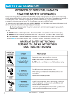
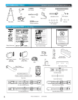
Installation Manual for assembly steps. Procéder selon les instructions stipumléoenstadgaenàs sleuimvraen.uel d'installation pour les étapes de Box Contents Sheet Adjustable wrench Wire strippers 1/4", 7/16", 3/8" and 1/2" Sockets Hammer Child can be pinned under automatic garage door. Death - Genie ChainLift 800 | Owner's Manual - Page 7
SCREW - 5/16'' x 2'' SELF DRILLING SCREW - 1/4 -20 x 3/4'' DOOR BRACKET HEX BOLT - 5/16 -18 x 3/4'' SELF LOCKING NUT - 5/16 x 1- 1/4'' WIRE NUT (GREY) REMOTE WITH BATTERY Safe-T-Beam® SOURCE/SENSOR & WIRE SET LIGHT COVER - WHITE QUANTITY 2 8 8 3 1 1 1 2 5 5 2 3 PARTS? Please call toll free - 1.800 - Genie ChainLift 800 | Owner's Manual - Page 8
1-PIECE RAIL HARDWARE ASSEMBLED VIEW FOR HELP-1.800.354.3643 OR WWW.GENIECOMPANY.COM Power Cord Rail with chain Tensioner CHAIN HIGH SPRING TENSION RseCerpvaaicniresCpoerarasudosjnuesutsSmineegrniptosromupsuesrItntbojeoulmsryaandoderibnDystareutarcattiihnoends - Genie ChainLift 800 | Owner's Manual - Page 9
If you have questions or do not understand an instruction, call The Genie Company or an authorized Genie® Dealer.) 2. Install only on a properly balanced sectional garage door. An improperly balanced door could cause severe injury. Have a trained door system technician make repairs or adjustments to - Genie ChainLift 800 | Owner's Manual - Page 10
RAILS Belt Rail A Tensioner Pulley B Center Rail Chain Tensioner Pulley Center Rail End Rail Rail Assembly for BELT DRIVE OPENER NOTE: For split rail clamps, nuts, and bolts locate Bag 0 from Box 1. 3. Remove the two rail sections that are not connected to the belt and place them on floor (Fig - Genie ChainLift 800 | Owner's Manual - Page 11
and/or cables and disable garage door lock NOW before continuing with installation (Fig. 1-8). Set assembled power head and rail aside. Begin with Section 2 INSTALLATION. Assembly for BELT DRIVE OPENER NOTE: For power head and rail assembly locate Bag 1 from Box 1. NOTE: Copy serial number from - Genie ChainLift 800 | Owner's Manual - Page 12
2 OPENER INSTALLATION HEADER AND DOOR MOUNTING BRACKETS: WARNING Header bracket must be fastened to garage framing. Do NOT fasten to drywall, particle board, plaster or other such materials. 1. Finding header bracket mounting location. • Close garage door. - Use a pencil and level. a) Mark center of - Genie ChainLift 800 | Owner's Manual - Page 13
open ceilings, straps may attach directly to joists or trusses. Depending on the garage construction, extra framing material (not provided) which may be required should be installed bolts and nuts. • Carefully raise and lower door manually. Ensure door does not contact any section of power head or - Genie ChainLift 800 | Owner's Manual - Page 14
braced before mounting door opener. Contact door manufacturer or distributor for a bracing kit. The Genie Company is not responsible for damage caused due to improperly braced door. NOTE: For door bracket and bolts locate Bag 4 from Box 2. 1. Finding door bracket mounting location. • Door bracket is - Genie ChainLift 800 | Owner's Manual - Page 15
from Box 2. 1. Wall Control location. • Wall Control location should be in direct sight of door. • It should be at least five feet (5') above floor to prevent small children from operating door. • It must be away from any moving parts. (You should NOT be able to reach the garage door while standing - Genie ChainLift 800 | Owner's Manual - Page 16
the center of this manual. - Stick label on wall near Wall Control. Vacation Locking Switch - LOCK disables controls after 1 door is completely closed - UNLOCK allows controls to work normally Door Control "Open/Close" Button - Open and closes door from 2 inside garage 3 Independent Light Control - Genie ChainLift 800 | Owner's Manual - Page 17
power cord-UNPLUG IT NOW! NOTE: The opener will not close the door automatically unless the Safe-T-Beam® System is installed. NOTE: For Sensors, screws, wire, and insulated staples locate items and Bag 8 from Box 3. 1. Mounting brackets. • Mark both sides of garage door frame or wall no higher than - Genie ChainLift 800 | Owner's Manual - Page 18
: For rear cover locate Box 4. 5. Attach Safe-T-Beam® wire to power head wire terminal. • Route Safe-T-Beam® wires through wire guide on power head. - . wire guide 65 432 1 - Confirm wire lock by lightly tugging on the wire. The wire should remain in the terminal hole. • Do not install the white - Genie ChainLift 800 | Owner's Manual - Page 19
, the garage door will reverse automatically to its fully opened position. (Meanwhile, the opener light will keep blinking until door moves to its fully opened position.) 4. If the Safe-T-Beam® System fails, loses power, or is installed improperly, press and hold the Wall Control "open/close" button - Genie ChainLift 800 | Owner's Manual - Page 20
• Close Travel Limit, • Open Travel Limit, Adjust Closing Force Adjust Opening Force Transmitter Programming Limit Controls location on power head. LED Indicator Light Open Open Set Limit Travel Limit Button Up Force OPEN Control Adjustment To Garage Door SET LEARN MANUAL LIMIT FORCE SET - Genie ChainLift 800 | Owner's Manual - Page 21
TOWARD THE OPENER TO RECONNECT PULL TOWARD DOOR FIG. 6-3 Engage/Disengage Carriage Lock. UP/DOWN FORCE 1. By turning the "Close Force Control" CLOSE clock- wise, the DOWN force can be increased. By turning the "Close Force Control" CLOSE counterclockwise, the DOWN force can be decreased. Set the - Genie ChainLift 800 | Owner's Manual - Page 22
-T-Beam® System is installed. CONTACT REVERSE TEST The force adjustments and limit switch settings MUST BE COMPLETED before testing. 1. Testing. • Open garage door using Wall Control. - Place a 2" x 4" board (laid flat) under center of garage door opening (FIG. 6-5). • Close door using Wall Control - Genie ChainLift 800 | Owner's Manual - Page 23
controls location on power head. LED Indicator Light Open Open Set Limit Travel Limit Button Up Force OPEN Control Adjustment NOTE: The door will stop automatically at the fully open or fully closed position. To Garage Door SET LOST OR STOLEN REMOTE 1. Clear memory. • Press and hold "Learn - Genie ChainLift 800 | Owner's Manual - Page 24
locate Box 4. 1. Light bulb. • Recommendations. - Do NOT use a short neck bulb. - Light bulbs should be no more than 60 Watts. - Use a heavy duty service bulb for longer life. • Screw 1 bulb into each socket. 2. Lens. • Select a white (lamp) cover. • On the power head end nearest the garage door - Genie ChainLift 800 | Owner's Manual - Page 25
repairs to cables, spring assemblies, and other hardware. 8. SAVE THESE INSTRUCTIONS. If you have any questions, please do not hesitate to contact Genie® customer service at: 1.800.354.3643 10 MAINTENANCE WARNING • Garage door hardware (springs, cables, brackets, pulleys, etc.) are under extreme - Genie ChainLift 800 | Owner's Manual - Page 26
CIRCUIT WIRING DIAGRAM FOR HELP-1.800.354.3643 OR WWW.GENIECOMPANY.COM Opener circuit wiring diagram. This wiring de câblage est indiqué à titre de référence uniquement. WARNING ADVERTENCIA AVERTISSEMENT Opening Cover May Cause Electric Shock. Abrir la tapa puede causar choques eléctricos. - Genie ChainLift 800 | Owner's Manual - Page 27
"OPEN" limit setting (See section 6 ). • Check "OPEN FORCE" adjustment (See section 6 ). • WARNING: If you suspect a problem with the garage door hardware or springs, contact an authorized Genie® Dealer or a trained door system technician, or contact The Genie Company at 1-800-35-GENIE. • Check door - Genie ChainLift 800 | Owner's Manual - Page 28
• Push transmitter button to program (See section 7 ) • Set DOWN LIMIT programming • Check for obstruction, remove • Check for obstruction, remove. - Check door spring (See section 10) - Contact The Genie Company at 1-800-35-GENIE 2 BLINKS, Pause (Repeat) 3 BLINKS, Pause (Repeat) 4 BLINKS - Genie ChainLift 800 | Owner's Manual - Page 29
TRANSMITTER COMPLIANCE STATEMENT Transmitters comply with all United States and Canadian legal requirements as of the date of manufacture. No warranty is made that they comply with all legal requirements of any other jurisdiction. If transmitters are to be used in another country, the importer must - Genie ChainLift 800 | Owner's Manual - Page 30
parts from clearance or open box sales, or repairs or maintenance to door components. ALL EXPRESS AND IMPLIED WARRANTIES FOR THE PRODUCT, INCLUDING BUT NOT LIMITED and identification as the original purchaser. Call Genie® Customer Service toll free at 1-800-354-3643 to speak with a trained
-
 1
1 -
 2
2 -
 3
3 -
 4
4 -
 5
5 -
 6
6 -
 7
7 -
8
-
9
-
10
-
11
-
12
-
13
-
14
-
15
-
16
-
17
-
18
-
19
-
20
-
21
-
22
-
23
-
24
-
25
-
26
-
27
-
28
-
29
-
30
 |
 |

Includes: 2-Bulb Light System
Wall Console
Includes INTELLICODE
®
Remote Control
Safe-T-Beam
®
System must be installed to close door.
For use only with sectional doors.
Homelink
®
and Car2U
®
compatible
For Answers and Assistance:
1.800.354.3643
or visit www.geniecompany.com
SAVE THIS MANUAL FOR FUTURE REFERENCE
Installer:
Leave this manual
with homeowner.
PN# 37026500123,
5/15/2009
Homelink
®
is a registered trademark of
Johnson Controls Technology Company.
Car2U
®
is a registered trademark of
Lear Corporation.
© GMI Holdings, Inc. d/b/a The Genie Company
Models 2022/2024/2042
GARAGE DOOR OPENERS
ALWAYS AT YOUR COMMAND