Genie ChainLift 800 Owner's Manual - Page 16
Securely fasten wires., Fig. 3-2 on, previous Do NOT install rear cover yet., Mounting, Fig. 3
 |
View all Genie ChainLift 800 manuals
Add to My Manuals
Save this manual to your list of manuals |
Page 16 highlights
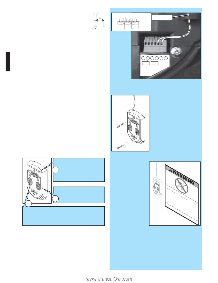
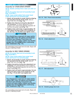
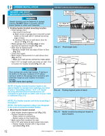
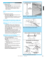
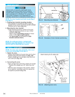
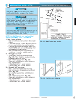
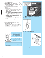
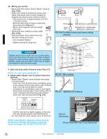
3. Securely fasten wires. • Securely fasten wires to ceiling and wall using insulated staples provided. - Use insulated staples. - Staples should be snug only. • If rear cover is attached to power head, Insulated Staple remove it. • On power head: - Route Wall Control wires through wire guide on power head. - Split and strip ends of wire (Fig. 3-2 on previous page). - Insert wire into terminal holes and lightly press in the orange locking clips above each terminal hole. (You can use a pencil or small screwdriver to comfortably press in locking clips.) The white wire into #1 terminal hole and striped wire into the #2 terminal hole. - Confirm wire lock by lightly tugging on the wire. The wire should remain in the terminal hole. • Do NOT install rear cover yet. Locking Clips Terminal Holes 6 54 321 wire guide 6 54 3 21 +- PB Infared Sensor (Power Head With Rear Cover Removed) FIG. 3-3 Insert wires. 4. Mounting. • Fasten Wall Control to wall with 2 screws (provided) (Fig. 3-4). • Remove protective backing from "Entrapment" warning label (Fig. 3-5). The "Entrapment" label is located in the center of this manual. - Stick label on wall near Wall Control. Vacation Locking Switch - LOCK disables controls after 1 door is completely closed - UNLOCK allows controls to work normally Door Control "Open/Close" Button - Open and closes door from 2 inside garage 3 Independent Light Control - Controls door opener lights from inside garage - Energy-Saver shut-off turns OFF lights 3 minutes after door activation FIG. 3-4 Mounting Wall Control. FIG. 3-5 DCehailAeNNItdfhmleewpcTovveeaeaeerrsIIRPrnyffMgsrrtlesodasobofedopcllueeeeeoenonnrektrrnttto1ecwoeif1i/parccoarys2eyil-llDoshhioiuspncntrpupoiiioctlsellrlo'nnehiddnmftnolrarnooeeioweintnwuoleblvsnadrojeereesvPejutasruolmctrdmaeisu'tleoncesrork,ef(eno.vgoydcmonvpenhrodeneoaix2tuldcordrtnchesoxr'tosousaeo4lrrprynarhwoundleatl:a.aaoaaoirnlincclcdorpuhcttir,ooef,unoe(ltnaaarvnstonetdrnteos)lpjtueldrmue.roaiastgolneishrtrttaihlfro.so5clotprbtlfmoioae.ercuerebnn.tpoeetatglltrav.br.ocoaoievnnrelsogafopl.ogeordnre)oeu..rosd. ero. or. ©1999 Mounting Entrapment warning label. 16 PN# 37026500123 05/15/2009
-
 1
1 -
2
-
3
-
4
-
5
-
6
-
7
-
8
-
9
-
10
-
 11
11 -
 12
12 -
 13
13 -
 14
14 -
 15
15 -
 16
16 -
 17
17 -
 18
18 -
 19
19 -
 20
20 -
 21
21 -
22
-
23
-
24
-
25
-
26
-
27
-
28
-
29
-
30
 |
 |