Genie ChainLift 800 Owner's Manual - Page 19
Connecting To Power, With Grounded Plug, Infrared Protection Function, With Permanent Wiring,
 |
View all Genie ChainLift 800 manuals
Add to My Manuals
Save this manual to your list of manuals |
Page 19 highlights
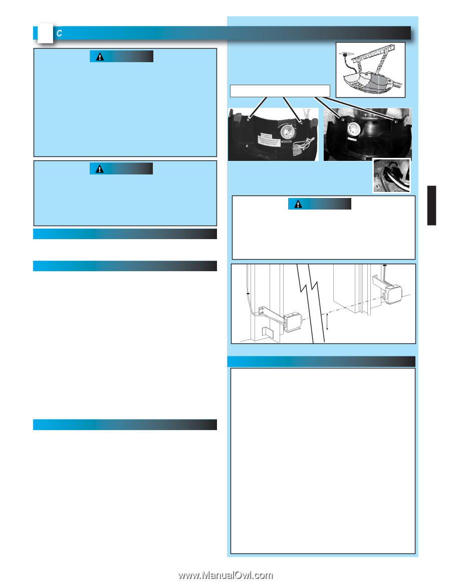
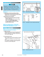
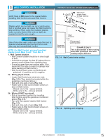
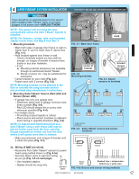
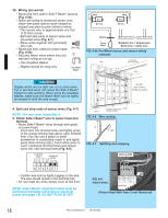
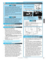
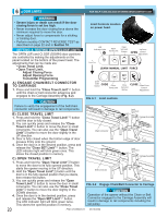
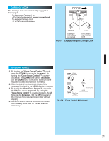
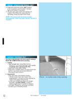
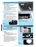
5 CONNECTING TO POWER FOR HELP-1.800.354.3643 OR WWW.GENIECOMPANY.COM WARNING • To reduce the risk of electrical shock, this equipment has a grounded type plug that includes a third (grounding) pin. This plug will only fit a grounded type outlet. If you do not have a grounded outlet, contact a qualified licensed electrician to install one. DO NOT alter the plug in any way. The door opener must be properly grounded in order to prevent personal injury and damage to the components. • DO NOT remove motor cover. All work performed on motor must be done by a trained door system technician. FIG. 5-1 Connect to power. Motor Cover Screws CAUTION • Check local building codes to make sure that you are not required to have your garage door opener permanently wired, with circuit breaker protection. If building codes require door opener to be permanently wired have a qualified licensed electrician connect power with permanent wiring. WITH GROUNDED PLUG: Plug the opener into a properly grounded electrical outlet (Fig. 5-1). WITH PERMANENT WIRING: Instructions for Electrician. • Remove power from circuit. • Remove rear cover and motor cover. - Remove four motor cover screws (Fig. 5-2). • Remove existing power cord and strain relief from the 7/8" dia. hole and discard (Fig. 5-3). • Connect permanent wiring to power head using 7/8" diameter hole. - White to white/black to black/ground to green. - Use only UL recognized wire nuts. • Wires inside the power head must be at least 6" in length. • Replace motor cover and rear cover and re-energize the circuit. NOTE: The Genie Company is not responsible for charges resulting from work performed by an independent electrician. WITH POWER SUPPLIED: Check Safe-T-Beam® alignment (Fig. 5-4). • Insure that no part of door or its hardware is in path between lenses of source and sensor. • Insure that tops of lenses are between 5" - 6" above the floor (Fig. 5-4). The brackets are flexible, and can be adjusted slightly if needed. • Adjust the Red LED transmitter by aiming the unit directly at the Green LED receiver. Use the adjustment screw located on the top of the transmitter housing to make adjustments. • The Red LED transmitter will blink if there is a misalignment. When the LED units are aligned the Red LED will remain ON continuously. • After the alignment is finished tighten the adjustment screws on both sensors. FIG. 5-2 FIG. 5-3 Remove motor cover. (Electrican ONLY) Power cord strain relief. CAUTION • Do NOT use an extension cord. • Do NOT use a portable generator. This product is designed to operate using standard household current. • Do NOT use alternate power supplies. 6" 5" max min from from floor floor FIG. 5-4 Check Safe-T-Beam® alignment. INFRARED PROTECTION FUNCTION 1. When the garage door is opening, its movement will not be influenced if the Safe-T-Beam® is obstructed. 2. If the Safe-T-Beam® is obstructed before the garage door fully closes, the door will not close. 3. When the garage door is closing, if Safe-T-Beam® is cut off by people or obstacle, the garage door will reverse automatically to its fully opened position. (Meanwhile, the opener light will keep blinking until door moves to its fully opened position.) 4. If the Safe-T-Beam® System fails, loses power, or is installed improperly, press and hold the Wall Control "open/close" button until the door reaches its fully closed position. The LED indicator light on the power head will be green and blink twice (Pattern: ☼☼ pause ☼☼ pause) to inform you to eliminate the problem first. If you release the "open/close" button on the Wall Control during the closing movement the door will reverse automatically to its fully opened position. PN# 37026500123 05/15/2009 19
-
 1
1 -
2
-
3
-
4
-
5
-
6
-
7
-
8
-
9
-
10
-
11
-
12
-
13
-
 14
14 -
 15
15 -
 16
16 -
 17
17 -
 18
18 -
 19
19 -
 20
20 -
 21
21 -
 22
22 -
 23
23 -
 24
24 -
25
-
26
-
27
-
28
-
29
-
30
 |
 |