Gigabyte C7V7-CSI Manual
Gigabyte C7V7-CSI Manual
 |
View all Gigabyte C7V7-CSI manuals
Add to My Manuals
Save this manual to your list of manuals |
Gigabyte C7V7-CSI manual content summary:
- Gigabyte C7V7-CSI | Manual - Page 1
GA-C7V7-RH VIA C7 Processor Motherboard User's Manual Rev. 100 12ME-C7V7RH-1001R - Gigabyte C7V7-CSI | Manual - Page 2
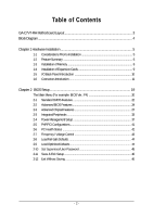
Table of Contents GA-C7V7-RH Motherboard Layout 3 Block Diagram ...4 Chapter 1 Hardware Installation 5 1-1 Considerations Prior to Installation 5 1-2 Feature Summary 6 1-3 Installation of Memory 8 1-4 Installation of Expansion Cards 9 1-5 I/O Back Panel Introduction 10 1-6 - Gigabyte C7V7-CSI | Manual - Page 3
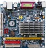
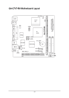
GA-C7V7-RH Motherboard Layout KB MS RCA SV BIOS CPU_FAN VIA C7 CPU COMB VGA VIA CN700 LPT COMA IT8712 F_USB2 F_USB1 CLR_CMOS USB RTL8100C VT8237R Plus BAT F_AUDIO LAN USB CD_IN SATA2 AUDIO CODEC SPDIF_IO SATA1 PCI1 GA-C7V7-RH DDRII ATX IDE1 IDE2 SYS_FAN F_PANEL - 3 - - Gigabyte C7V7-CSI | Manual - Page 4
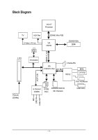
Block Diagram VIA C7 Processor TV VGA Port S-Video / AV out RJ45 533/400 MHz FSB VIA CN700 533/400 MHz DDRII 66MHz V_Link 1 PCI RTL8100C VIA VT8237R Plus LPC BUS 2 Serial ATA IT8712 BIOS LPT Port AC97 Link PCICLK (33MHz) 6 Channel CODEC 8 USB ATA33/66/100/133 Ports IDE Channels - Gigabyte C7V7-CSI | Manual - Page 5
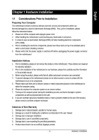
installation, please follow the instructions below: 1. Please turn off the information in the provided manual. 3. Before using the product about any installation steps or have a problem related to the use of the product, the conditions recommended in the user manual. 3. Damage due to improper - Gigabyte C7V7-CSI | Manual - Page 6
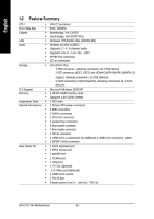
Onboard RTL8100C chip (10/100 Mbit) Audio Š Realtek ALC653 CODEC Š Supports 2 / 4 / 6 channel audio Š Supports Line In ; Line Out ; MIC Š SPDIF Out connection Š CD (Optional) Š 4 USB 2.0/1.1 ports Š 1 RJ-45 port Š 3 audio jacks (Line In / Line Out / MIC In) GA-C7V7-RH Motherboard - 6 - - Gigabyte C7V7-CSI | Manual - Page 7
System voltage detection Š CPU / System temperature detection Š CPU / System fan speed detection Š CPU warning temperature Š CPU / System fan failure warning Š Supports CPU / System Smart Fan function Š Use of licensed AWARD BIOS Š Mini-ITX form factor; 17.0cm x 17.0cm - 7 - Hardware Installation - Gigabyte C7V7-CSI | Manual - Page 8
. If you are unable to insert the module, please switch the direction. The motherboard supports DDR II memory modules, whereby BIOS will automatically detect memory capacity and specifications. Memory modules installation steps when you wish to remove the DIMM module. GA-C7V7-RH Motherboard - 8 - - Gigabyte C7V7-CSI | Manual - Page 9
1-4 Installation of Expansion Cards You can install your expansion card by following the steps outlined below: 1. Read the related expansion card's instruction document before installing the expansion card into the computer. 2. Remove your computer's chassis cover, screws and slot bracket from the - Gigabyte C7V7-CSI | Manual - Page 10
mouse, scanner, zip, speaker...etc. have a standard USB interface. Also make sure your OS supports USB controller. If your OS does not supportUSB controller, please contact OS vendor for possible patch or connector. MIC In Microphone can be connected to MIC In jack. GA-C7V7-RH Motherboard - 10 - - Gigabyte C7V7-CSI | Manual - Page 11
English 1-6 Connectors Introduction 9 5 1 10 12 2 7 11 6 4 5 8 3 1) ATX 2) IDE1/ IDE2 3) SATA1 / SATA2 4) CPU_FAN / SYS_FAN 5) F_PANEL 6) F_AUDIO 7) CD_IN 8) SPDIF_IO 9) COMB 10) F_USB1 / F_USB2 11) BAT 12) CLR_CMOS - 11 - Hardware Installation - Gigabyte C7V7-CSI | Manual - Page 12
used that does not provide the required power, the result can lead to an unstable system or a system that is unable to start. 10 20 GA-C7V7-RH Motherboard 1 11 Pin No. 1 2 3 4 5 6 7 8 9 10 11 12 13 14 15 16 17 18 19 20 Definition 3.3V 3.3V GND +5V GND +5V GND Power - Gigabyte C7V7-CSI | Manual - Page 13
IDE devices, please set the jumper on one IDE device as Master and the other as Slave (for information on settings, please refer to the instructions located on the IDE device). Before attaching the IDE cable, please take note of the foolproof groove in the IDE connector. 40 39 2 IDE1 1 IDE2 - Gigabyte C7V7-CSI | Manual - Page 14
) MSG+ MSG- PWRSW GND ACT_LED- 2 10 1 9 HD+ HDRESET GND ACT_LED+ Pin No. 1 3 5 7 9 Definition HD_LED+ HD_LEDGND RESET ACT_LED+ Pin No. 2 4 6 8 10 Definition MSGLED+ MSGLEDPWRSW GND ACT_LED- GA-C7V7-RH Motherboard - 14 - - Gigabyte C7V7-CSI | Manual - Page 15
pin assigments on the cable are the same as the pin assigments on the MB header. To find out if the chassis you are buying support front audio connector, please contact your dealer.Please note, you can have the alternative of using front audio connector or of using rear audio connector - Gigabyte C7V7-CSI | Manual - Page 16
to work or even damage it. For optional COMB cable, please contact your local dealer. 10 9 2 1 Pin No. 1 2 3 4 5 6 7 8 9 10 Definition NDCDBNSINB NSOUTB NDTRBGND NDSRBNRTSBNCTSBNRIBNo Pin GA-C7V7-RH Motherboard - 16 - - Gigabyte C7V7-CSI | Manual - Page 17
is incorrectly replaced. Replace only with the same or equivalent type recommended by the manufacturer. Dispose of used batteries according to the manufacturer's instructions. If you want to erase CMOS... 1. Turn off the computer and unplug the power cord. 2. Gently take out the battery and put it - Gigabyte C7V7-CSI | Manual - Page 18
English 12) CLR_CMOS (Clear CMOS) You may clear the CMOS data to its default values by this header. To clear CMOS, temporarily short the two pins. Default doesn't include the jumper to avoid improper use of this header. Open: Normal Short: Clear CMOS GA-C7V7-RH Motherboard - 18 - - Gigabyte C7V7-CSI | Manual - Page 19
English Chapter 2 BIOS Setup BIOS (Basic Input and Output System) includes a CMOS SETUP utility which allows user to configure required settings or to activate certain system features. The CMOS SETUP saves the configuration in the CMOS SRAM of the motherboard. When the power is turned off, the - Gigabyte C7V7-CSI | Manual - Page 20
be in safe configuration. „ Load Optimized Defaults Optimized Defaults indicates the value of the system parameters which the system would be in best performance configuration. GA-C7V7-RH Motherboard - 20 - - Gigabyte C7V7-CSI | Manual - Page 21
English „ Set Supervisor Password Change, set, or disable password. It allows you to limit access to the system and Setup, or just to Setup. „ Set User Password Change, set, or disable password. It allows you to limit access to the system. „ Save & Exit Setup Save CMOS value settings to CMOS and - Gigabyte C7V7-CSI | Manual - Page 22
and the system will skip the automatic detection step and allow for faster system start up. Manual User can manually input the correct settings Access Mode Use this to set the access mode for the hard start up. Capacity Capacity of currently installed hard disk. GA-C7V7-RH Motherboard - 22 - - Gigabyte C7V7-CSI | Manual - Page 23
detects the type of adapter used for the primary system monitor that must match your video display card and monitor. Although secondary monitors are supported, you do not have to select the type in setup. EGA / VGA Enhanced Graphics Adapter/Video Graphics Array. For EGA, VGA, SVGA, or PGA - Gigabyte C7V7-CSI | Manual - Page 24
, etc. Use < > or < > to select a device, then press to move it up, or to move it down the list. Press to exit this menu. GA-C7V7-RH Motherboard - 24 - - Gigabyte C7V7-CSI | Manual - Page 25
disk drive. The system will halt and the warning message will appear in the mean time. You can run anti-virus program to locate the problem. Enabled Activate automatically when the system boots up causing a warning message to appear when anything attempts to access the boot sector or hard disk - Gigabyte C7V7-CSI | Manual - Page 26
) Disabled Video shadow is desibled. Small Logo(EPA) Show Enabled Small logo(EPA) show is enabled .(Default Value) Disabled Small logo(EPA) show is desibled. GA-C7V7-RH Motherboard - 26 - - Gigabyte C7V7-CSI | Manual - Page 27
English 2-3 Advanced Chipset Features DRAM Clock/Drive Control AGP & P2P Bridge Control CPU & PCI Bus Control Memory Hole System BIOS Cacheable Video RAM Cacheable Init Display First Phoenix- AwardBIOS CMOS Setup Utility Advanced Chipset Features [Press Enter] [Press Enter] [Press Enter] [ - Gigabyte C7V7-CSI | Manual - Page 28
CPU & PCI Bus Control PCI Master 0 WS Write PCI Delay Transaction VLink mode selection VLink 8x Support DRDY_Timing Phoenix- AwardBIOS CMOS Setup Utility CPU & PCI Bus Control [Enabled] [Enabled] [By Auto 333MHz. ESC: Exit F1: General Help F7: Optimized Defaults GA-C7V7-RH Motherboard - 28 - - Gigabyte C7V7-CSI | Manual - Page 29
English DRAM Timing Auto By SPD Set DRAM timing auto by SPD.(Default Value) Manual Set DRAM timing by manually. SDRAM CAS Latency Set SDRAM CAS Latency toDDR / DDR2.5 / 4 Bank Interleave Disabled Set bank interleave to Disabled.(Default Value) Enabled Set bank interleave to Enabled. - Gigabyte C7V7-CSI | Manual - Page 30
. AGP Driving control Auto Auto detect AGP driving control. (Default value) Manual Set AGP driving control by manually. AGP Fast Write Disabled Disabled AGP Fast write function. (Default value) . Enabled Enabled direct fram buffer function. (Default value) GA-C7V7-RH Motherboard - 30 - - Gigabyte C7V7-CSI | Manual - Page 31
mode seclection By Auto VLink mode selection by automatically. (Default value) Mode 0 Set VLink mode to mode 0. Mode 1 Set VLink mode to mode 1. VLink 8x Support Disabled Disabled VLink 8x support. Enabled Enabled VLink 8x support.(Default value) - 31 - BIOS Setup - Gigabyte C7V7-CSI | Manual - Page 32
Hole Disabled Disabled this function. (Default value) 15M-16M Enabled VLink 8x support. System BIOS Cacheable Disabled Disabled System BIOS Cacheable. Enabled Enabled System BIOS Cacheable to VGA card. PCI slot Set Init display first to PCI.(Default value) GA-C7V7-RH Motherboard - 32 - - Gigabyte C7V7-CSI | Manual - Page 33
English 2-3 Integrated Peripherals VIA OnChip IDE Device VIA OnChip PCI Device SuperIO Device Onboard Lan Boot ROM Onboard H/W LAN Phoenix- AwardBIOS CMOS Setup Utility Integrated Peripherals [Press Enter] [Press Enter] [Press Enter] [Disabled] [Enabled] Item Help Menu Level : Move Enter: - Gigabyte C7V7-CSI | Manual - Page 34
VIA-3058 AC97 Audio OnChip USB Controller OnChip EHCI Controller USB Emulation x USB Keyboard Support x USB Mouse Support Phoenix- AwardBIOS CMOS Setup Utility VIA OnChip IDE Device [Auto] [All Enabled] IDE DMA transfer access. (Default value) Disable this function. GA-C7V7-RH Motherboard - 34 - - Gigabyte C7V7-CSI | Manual - Page 35
English On-Chip IDE Channel0 Enabled Enable onboard 1st channel IDE port. (Default value) Disabled Disable onboard 1st channel IDE port. On-Chip IDE Channel1 Enabled Enable onboard 2nd channel IDE port. (Default value) Disabled Disable onboard 2nd channel IDE port. IDE Prefetch Mode - Gigabyte C7V7-CSI | Manual - Page 36
Support Disabled Disable USB keyboard support. Enabled Enable USB keyboard support.(Default value) USB Mouse Support Disabled Disable USB mouse support. Enabled Enable USB mouse support H/W LAN function. (Default value) Disabled Disable this function. GA-C7V7-RH Motherboard - 36 - - Gigabyte C7V7-CSI | Manual - Page 37
English 2-4 Power Management Setup ACPI function ACPI Suspend Type Power Management Option HDD Power Down Suspend Mode Video Off Option Video Off Method Modem Use IRQ Soft-Off by Power button Run VGA BIOS if S3 Resume AC Loss Auto Restart IRQ/Event Activity Detect Phoenix- AwardBIOS CMOS Setup - Gigabyte C7V7-CSI | Manual - Page 38
when gets into Green mode for Green monitor Blank screen power saving. (Default value) BIOS will only black monitor when gets into Green mode. DPMS Support BIOS will use DPMS Standard to control VGA card. (The Green type VGA card will turn of V/H-SYNC automatically - Gigabyte C7V7-CSI | Manual - Page 39
English Modem Use IRQ NA Set Modem use IRQ to NA. (Default value) 3 Set Modem use IRQ to 3. 4 Set Modem use IRQ to 4. 5 Set Modem use IRQ to 5. 7 Set Modem use IRQ to 7. 9 Set Modem use IRQ to 9. 10 Set Modem use IRQ to 10. 11 Set Modem use IRQ to 11. Soft-Off by Power button - Gigabyte C7V7-CSI | Manual - Page 40
this function. ON Enable this function. (Default value) IRQ (3,4,5,6,7,8,9, 10,11,12,13,14,15) Disabled Disable this function. (Default value) Enabled Enable this function. GA-C7V7-RH Motherboard - 40 - - Gigabyte C7V7-CSI | Manual - Page 41
data. (Default value) Disabled Disabled this function. Resources Controlled By Auto(ESCD) BIOS automatically use these PnP rescuers. (Default value) Manual User can set the PnP resource (I/O Address, IRQ & DMAchannels) used by legacy ISA DEVICE. PCI/VGA Palette Snoop Enabled For having - Gigabyte C7V7-CSI | Manual - Page 42
's voltage status automatically. Current System / CPU Temperature Detect System / CPU temperature automatically. Current CPU / SYSTEM FAN Speed (RPM) Detect CPU / System fan speed status automatically. GA-C7V7-RH Motherboard - 42 - - Gigabyte C7V7-CSI | Manual - Page 43
English 2-7 Frequency / Voltage Control Auto Detect PCI Clk Spread Spectrum CPU / PCIEX / AGP / PCI DIMM OverVoltage Phoenix- AwardBIOS CMOS Setup Utility Frequency / Voltage Control [Enabled] [+-0.25%] [Default] [Auto] Item Help Menu Level : Move Enter: Select F5: Previous Values +/-/PU/PD: - Gigabyte C7V7-CSI | Manual - Page 44
: Save & Exit Setup : Select Item Load Optimized Defaults Selecting this field loads the factory defaults for BIOS and Chipset Features which the system automatically detects. GA-C7V7-RH Motherboard - 44 - - Gigabyte C7V7-CSI | Manual - Page 45
English 2-10 Set Supervisor/User Password Phoenix- AwardBIOS CMOS Setup Utility Standard CMOS Features Advanced BIOS Features Advanced Chipset Features Integrated PeripherEalnster Password: Power Management Setup PnP/PCI Configurations PC Health Status Frequency/Voltage Control Load Fail-Safe - Gigabyte C7V7-CSI | Manual - Page 46
: Save & Exit Setup Abandon all Data : Select Item Type "Y" will quit the Setup Utility without saving to RTC CMOS. Type "N" will return to Setup Utility. GA-C7V7-RH Motherboard - 46 - - Gigabyte C7V7-CSI | Manual - Page 47
- 47 - BIOS Setup English - Gigabyte C7V7-CSI | Manual - Page 48
English GA-C7V7-RH Motherboard - 48 -
-
 1
1 -
 2
2 -
 3
3 -
 4
4 -
 5
5 -
 6
6 -
 7
7 -
8
-
9
-
10
-
11
-
12
-
13
-
14
-
15
-
16
-
17
-
18
-
19
-
20
-
21
-
22
-
23
-
24
-
25
-
26
-
27
-
28
-
29
-
30
-
31
-
32
-
33
-
34
-
35
-
36
-
37
-
38
-
39
-
40
-
41
-
42
-
43
-
44
-
45
-
46
-
47
-
48
 |
 |

GA-C7V7-RH
VIA C7
Processor Motherboard
User's Manual
Rev. 100
12ME-C7V7RH-1001R