Gigabyte GA-2CEWH User Manual
Gigabyte GA-2CEWH Manual
 |
View all Gigabyte GA-2CEWH manuals
Add to My Manuals
Save this manual to your list of manuals |
Gigabyte GA-2CEWH manual content summary:
- Gigabyte GA-2CEWH | User Manual - Page 1
GA-2CEWH AMD Socket 940 Dual Processor Motherboard USER'S MANUAL AMD Opteron™ Socket 940 Dual Processor Motherboard Rev. 1003 - Gigabyte GA-2CEWH | User Manual - Page 2
GA-2CEWH Motherboard Layout 7 Chapter 2 Hardware Installation Process 9 Step 1: Installing Processor and CPU Cooling Fan 10 Step1-1: Installing CPU 10 Step1-2: Installing Cooling Fan 12 Step 2: Install memory Chapter 3 BIOS Setup 35 Main ...37 Advanced 41 Hardware Monitoring ...42 BIOS Event - Gigabyte GA-2CEWH | User Manual - Page 3
Block Diagram 72 Chapter 5 Application Driver Installation 73 A.NVDIA Chipset Driver Installation 73 B.Broadcom LAN Driver Installation 75 C.Realtek AC97 Driver Installation 77 D.AMD System Interrupt Controller Driver Installation 78 E.DirectX 9.0 Driver Installation 80 Chapter 6 Appendix 81 - Gigabyte GA-2CEWH | User Manual - Page 4
GA-2CEWH Motherboard Item Checklist ; The GA-2CEWH motherboard ; SATA Cable x 4 ; CD for motherboard driver & utility ; GA-2CEWH user's manual ; I/O shield x 1 ; FDD Cable x 1 WARNING! Computer motherboards and expansion cards contain very delicate Integrated Circuit (IC) chips. To protect them - Gigabyte GA-2CEWH | User Manual - Page 5
Introduction Summary of Features Form Factor 30.4cm x 33.0cm EATX size form factor, 8 layers PCB. Motherboard GA-2CEWH Motherboard CPU Support Dual Opteron processors (Sledge Hammer) The HyperTransport link of the AMD Opteron processor is capable of operating at 400, 800, 1200, and 1600 MT - Gigabyte GA-2CEWH | User Manual - Page 6
GA-2CEWH Motherboard On-Board Peripherals RAID Supported Hardware Monitor Power Managerment Features IEEE1394A Audio On-Board LAN PS/2 Connector BIOS Additional Features 1 Floppy port supports 2 FDD with 360K, 720K,1.2M, 1.44M and 2.88M bytes. 1 Parallel port supports Normal/EPP/ECP mode 1 Serial - Gigabyte GA-2CEWH | User Manual - Page 7
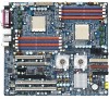
Introduction GA-2CEWH Motherboard Layout Y Z1 2 18 19 20 21 2223 24 25 F 6 16 W 10 11 12 13 14 G 15 X V H U 7 27 B 26 8 C 4 9 E D S R Q T KI J P 5 LO N M A 3 17 7 - Gigabyte GA-2CEWH | User Manual - Page 8
GA-2CEWH Motherboard A. CPU0 1. SPDIF_IO_IN_OUT B. CPU1 2. CENTER_SOUOUND C. NVIDIA nForce Profession 20503. FAN1 (CPU0 Fan) D. NVIDIA nForce Profession 22204. FAN5 (CPU1 Fan) E. AMD8132 5. FAN4 (Front Fan) F. Broadcom BCM5751T 6. FAN3 ( - Gigabyte GA-2CEWH | User Manual - Page 9
: Step 1- Install the Central Processing Unit (CPU) Step 2- Install memory modules Step 3- Install expansion cards Step 4- Connect ribbon cables, cabinet wires, and power supply Step 5- Setup BIOS software Step 6- Install supporting software tools Step 3 Step 2 Step 5 Step 4 Step 1 Step 4 Step - Gigabyte GA-2CEWH | User Manual - Page 10
GA-2CEWH Motherboard Step 1: Installing Processor and CPU Cooling Fan Before installing the processor thermal grease on the processor before placing cooling fan. 4. Please make sure the CPU type is supported by the motherboard. 5. If you do not match the CPU socket Pin 1 and CPU cut edge well, it - Gigabyte GA-2CEWH | User Manual - Page 11
Hardware Installation Process Figure 3. A1 pin location on the Socket and Processor.Move the socket lever to the locked position while holding pressure on the center of the processor. Step 4. When the processor installation is completed, apply thermal grease to the processor(as shown in Figure 4) - Gigabyte GA-2CEWH | User Manual - Page 12
GA-2CEWH Motherboard Step1-2: Installing Cooling Fan Step 1. Attach th cooling fan clip to the processor scoket. Align the heatsink assembly with the support frame mating with the backer plate standoffs as shown in Figure 5&6. Step 2. Coonect the processor fan cable to the processor fan connector. - Gigabyte GA-2CEWH | User Manual - Page 13
orientation will cause improper installation. Please change the insert orientation. The motherboard has 8 dual inline memory module (DIMM) sockets. The BIOS will automatically detects memory type and size. To install the memory module, just push it vertically into the DIMM socket .The DIMM module - Gigabyte GA-2CEWH | User Manual - Page 14
GA-2CEWH Motherboard Total Memory Sizes With Registered DDR DIMM Devices used on DIMM 64 Mbit ( socket. Firmly insert the DIMMinto the socket until the retaining clips snap back in place. 3. The processor supports 64-bit mode and 128-bit mode configuration of the DIMMs. In 64 bit mode, only DIMM 0 - Gigabyte GA-2CEWH | User Manual - Page 15
Table 1. Vaild DIMM Configuration for 64 bit Mode DIMM 0 (MB) DIMM 2 (MB) X 256 256 256 X 512 512 512 X 1024 1024 1024 X 2048 2048 2048 X 4096 4096 4096 Note: X = Do not populate Hardware Installation Process Table 2. Vaild DIMM Configuration for 128 bit Mode Logical DIMM 0 - Gigabyte GA-2CEWH | User Manual - Page 16
GA-2CEWH Motherboard Step 3: Install expansion cards 1. Read the related expansion card's instruction document before install the expansion card into the . 7. Power on the computer, if necessary, setup BIOS utility of expansion card from BIOS. 8. Install related driver from the operating system. 16 - Gigabyte GA-2CEWH | User Manual - Page 17
Hardware Installation Process Step 4: Connect ribbon cables, cabinet wires, and power supply Step4-1:I/O Back Panel Introduction 17 - Gigabyte GA-2CEWH | User Manual - Page 18
GA-2CEWH Motherboard PS/2 Keyboard and PS/2 Mouse Connector To install a PS/2 port keyboard and mouse, plug the mouse to the upper port (green) and the keyboard to the lower port (purple). Parallel Port / Serial Port This connector supports 1 standard COM port and 1 Parallel port. Device like - Gigabyte GA-2CEWH | User Manual - Page 19
Audio Connectors Line Out (Front Speaker) Line In (Rear Speaker) MIC In (Center and Subwoofer) Hardware Installation Process ¾ After install onboard audio driver, you may connect speaker to Line Out jack, micro phone to MIC In jack. Device like CD-ROM , walkman etc can be connected to Line- - Gigabyte GA-2CEWH | User Manual - Page 20
GA-2CEWH Motherboard Step4-2: Connectors Introduction R ST U 3 P O N L Y Z M V 2 K J I EC H D GF5 Q 6 20 4 1 B A X W - Gigabyte GA-2CEWH | User Manual - Page 21
A) AXT2 B) ATX1 C) IDE1 D) IDE2 E) FDD F) F_USB2 G) F_USB1 H) SATA0 I) SATA1 J) SATA2 K) SATA3 L) CI M) F_Panel N) WOL O) WOR P) F_Audio Q) F_1394 Connector Introduction R) AUX_IN S) CD_IN1 T) SPDIF_IO U) SUR_CEN1 V) BT W) FAN1 X) FAN5 Y) IO4_FAN Z) CK804_FAN 1) FAN2 2) FAN4 3) FAN3 4) PWR_JP 5) - Gigabyte GA-2CEWH | User Manual - Page 22
GA-2CEWH Motherboard A ) ATX2 ¾ AC power cord should only be connected to your power supply unit after ATX power cable and other related devices are GND 87 21 Pin No. 1 2 3 4 5 6 7 8 Definition GND +12v GND +12V GND +12V GND +12V ¾This connector (ATX +12V) is used only for CPU Core Voltage. 22 - Gigabyte GA-2CEWH | User Manual - Page 23
ribbon cable must be the same side with the Pin1. 1 2 39 40 E ) FDD1 (Floppy Connector) Please connect the floppy drive ribbon cables to FDD. It supports 360K,720K,1.2M,1.44M and 2.88Mbytes floppy disk types. The red stripe of the ribbon cable must be the same side with the Pin1. 12 - Gigabyte GA-2CEWH | User Manual - Page 24
GA-2CEWH Motherboard F ) F_ USB2 (Front USB Connector) PIN No. Definition 1 Do Not Connect 2 Do Not Connect 11 13 4 Power Power 5 Data- 12 26 Data- 7 Data+ 8 Data+ 9 GND - Gigabyte GA-2CEWH | User Manual - Page 25
TXP TXN GND RXN RXP GND SATA0~3 L ) CI (CASE OPEN) This 3 pin connector allows your system to enable or disable the "case open" item in BIOS if the system case begin remove. Pin No. 1 2 3 Definition GND INTRUDER# NC 25 - Gigabyte GA-2CEWH | User Manual - Page 26
GA-2CEWH Motherboard M ) F_Panel1 (2X10 Pins) Please connect the power LED, PC speaker, reset switch and power switch etc of your chassis front panel to the front panel - Gigabyte GA-2CEWH | User Manual - Page 27
WOL (Wake On LAN Connector) This connector allows the remove servers to manage the system that installed this mainboard via your network adapter which also supports WOL. 1 Pin No. Definition 1 +5V SB 2 GND 3 Signal O ) WOR (Wake on Ring Connector) 1 Pin No. Definition 1 Ring 2 GND 27 - Gigabyte GA-2CEWH | User Manual - Page 28
GA-2CEWH Motherboard P ) F_Audio (Front Audio connector) If you want to use Front Audio connector is the same as the pin assigment on the MB header. To find out if the chassis you are buying support front audio connector, please contact your dealer. Pin No. Definition 1 MIC 10 9 2 GND 3 REF - Gigabyte GA-2CEWH | User Manual - Page 29
Connector Introduction R ) AUX_IN ( AUX In Connector) Connect other device(such as PCI TV Tunner audio out)to the connector. Pin No. Definition 1 AUX-L 2 GND 3 GND 4 AUX-R 1 S ) CD_IN (CD IN,Black) Connect CD-ROM or DVD-ROM audio out to the connector. Pin No. 1 2 3 4 Definition CD-L GND - Gigabyte GA-2CEWH | User Manual - Page 30
GA-2CEWH Motherboard T )SPDIF_IO (Red Connector) The SPDIF output is capable of providing digital audio to external speakers or compressed AC3 data to an external Dolby Digital Decoder. - Gigabyte GA-2CEWH | User Manual - Page 31
the battery. 4.Plug the power cord and turn ON the computer. manufacturer's instructions. W / X ) FAN1 /FAN 5 (CPU 0/1 Fan Connectors) Please from running under abnormal condition or damaged by overheating.The CPU fan connector supports Max. current up to 600 mA. Note: Pin 4 is reserved for - Gigabyte GA-2CEWH | User Manual - Page 32
GA-2CEWH Motherboard Y ) IO4_FAN (NVIDIA IO-4 Chipset FAN connector) If you installed wrong direction, the Chip Fan will not work. Sometimes will damage the Chip Fan. Pin No. - Gigabyte GA-2CEWH | User Manual - Page 33
system case to lower the system temperature. FAN4 FAN2 1 Pin No. Definition 1 GND 2 12V 3 Sense 4 Control FAN5 4 ) PWR_JP (PS/2 Wake Up Power Source Jumper) 1 1-2 close:support PS2 wake up from S3 (Default) 1 2-3 close: Disable this function 33 - Gigabyte GA-2CEWH | User Manual - Page 34
GA-2CEWH Motherboard 5 ) CLR_CMOS1 (Clear CMOS Function) You may clear the CMOS data to short 1-2 pin. 1 1-2 close: Clear CMOS 1 2-3 close: Normal (Default) 6 ) BIOS_RE (BIOS Recovery Function) 1 1-2 close: Enable BIOS Recovery function 1 2-3 close: Disable BIOS Recovery function (Default) 34 - Gigabyte GA-2CEWH | User Manual - Page 35
Chapter 3 BIOS Setup BIOS Setup BIOS Setup is an overview of the BIOS Setup Program. The program that allows users to modify the basic system configuration. This type of information is stored in battery-backed CMOS RAM so that it retains the Setup information when the power is turned off. - Gigabyte GA-2CEWH | User Manual - Page 36
GA-2CEWH Motherboard GETTINGHELP Main Menu The on-line description of the highlighted setup function is displayed at the bottom of the screen. Status Page Setup Menu / Option Page Setup Menu Press F1 to pop up a small help window that describes the appropriate keys to use and the possible selections - Gigabyte GA-2CEWH | User Manual - Page 37
Setup Main Once you enter Phoenix BIOS Setup Utility, the Main Menu (Figure 1) will appear on drive 3 [None] Standard IDE drive 4 [None] Installed OS [Other] System Information System Memory 640KB Extended Memory 1022MB F1: Help Esc: Exit KL: Select Item IJ: Select Menu + -: Change - Gigabyte GA-2CEWH | User Manual - Page 38
GA-2CEWH Motherboard Diskette A This category identifies the type of floppy disk drive A to F that has been installed in the computer. There are two types: auto type, and manual type. Manual type is user-definable; Auto type which will automatically detect HDD type. Note that the specifications of - Gigabyte GA-2CEWH | User Manual - Page 39
BIOS Setup Multi-Sector Transfer This field displays the information of Multi-Sector Transfer Mode. Disabled: The data transfer from and to the device occurs one sector at a time. Auto: The data transfer from and to the device occurs multiple sectors at a time if the device supports it. Maximum - Gigabyte GA-2CEWH | User Manual - Page 40
GA-2CEWH Motherboard System Information This category includes the information of BIOS Version, BIOS Date,and MAC address. System Memory The POST of the BIOS will determine the amount of base (or conventional) memory installed in the system. The value of the base memory is typically 512K for systems - Gigabyte GA-2CEWH | User Manual - Page 41
Advanced Phoenix TrustedCore(tm) Setup Utility Main Advanced Security Power Boot Exit Hardware Monitoring Item Specific Help BIOS Event Logging Processor Hammer Configuration Chipset Diskette Controller ATA Controller Integrated Network Interface Integrated Audio Integrated USB - Gigabyte GA-2CEWH | User Manual - Page 42
GA-2CEWH Motherboard Hardware Monitoring PhoenixTrustedCore(tm) Setup Utility Advanced Hardware Monitoring Item Specific Help Realtime Sensors: F1: Help Esc: Exit KL: Select Item IJ: Select Menu + -: Change - Gigabyte GA-2CEWH | User Manual - Page 43
log. (Default vaule) Disabled Error will not be logged to the BIOS event log. View DMI external Log Press [Enter] to view the contents of the DMI Event Log. Clear BIOS event log Enabled Setting to enabled, system will clear BIOS event log after rebooting system. Disabled Disable this function. 43 - Gigabyte GA-2CEWH | User Manual - Page 44
GA-2CEWH Motherboard Processor PhoenixTrustedCore(tm) Setup Utility Advanced Processor Item Specific Help CPU0 Type: ) specification revision level. Some operating system will require 1.1 for compatibility reasons. 1.4 Support MPS Version 1.4 . (Default) 1.1 Support M PS Version 1.1. 44 - Gigabyte GA-2CEWH | User Manual - Page 45
Hammer Configuration BIOS Setup PhoenixTrustedCore(tm) Setup Utility Advanced Hammer Configuration Item Specific -Menu F10: Save&Exit Figure 2-4: Hammer Configuration HT-LDT Frequency Manually select HT-LINK frequency. Options 200MHz, 400MHz, 600MHz, 800MHz, and 1000MHz (Default values) 45 - Gigabyte GA-2CEWH | User Manual - Page 46
GA-2CEWH Motherboard MTRR Mapping Method Select the CPU Memory Type Range Register (MTRR) mapping method. Continuous Default method. (Default value) Dicrete Compatible with Linux AGP. Memhole mapping Remapping scheme of PCI memory hole. Hardware Select Hardware as the PCI memory hole. (Default value - Gigabyte GA-2CEWH | User Manual - Page 47
BIOS Setup DCACHE ECC Scrub CTL This option allows user to set the rates of background scrubbing for DCACHE lines. Enabled Set the rates of background - Gigabyte GA-2CEWH | User Manual - Page 48
GA-2CEWH Motherboard Chipset Advanced Chipset DRAM Bank Interleaving NODE memory Interleaving ACPI SRAT Table ECC Memory this function. NODE Memory Interleaving Auto BIOS will automatically detect function. ECC Memory Checking Enabled All memory modules in the system support parity ECC mode - Gigabyte GA-2CEWH | User Manual - Page 49
Change Values F5: Setup Defaults Enter: Select Sub-Menu F10: Save&Exit Figure 2-6: Diskette Controller Diskette Controller Auto BIOS will automatically start configuration for floppy diskette controller. (Default value) Enabled Enable floppy diskette controller. Disabled Disable this function - Gigabyte GA-2CEWH | User Manual - Page 50
GA-2CEWH Motherboard ATA Controller PhoenixTrustedCore(tm) Setup Utility Advanced ATA Controller Item Specific Help P-ATA Interface [Pata 1/2 + P- Serial ATA configured in native mode.Some operating systems do not support native IDE devices. This option requires two identical SATA devices. 50 - Gigabyte GA-2CEWH | User Manual - Page 51
Integrated Network Interface BIOS Setup PhoenixTrustedCore(tm) Setup Utility Advanced Integrated Network Interface Item Specific Help Integrated Network Interface 1 (Broadcom) Integrated Network Interface 2 (NVDIA) F1: Help Esc: Exit KL: - Gigabyte GA-2CEWH | User Manual - Page 52
GA-2CEWH Motherboard Integrated Network Interface 2 (NVDIA) Integrated Network Interface Enabled Enable onboard LAN (NVDIA) controller. (Default value) Disabled Disable this function. Latency Timer Default Options Minimum guaranteed - Gigabyte GA-2CEWH | User Manual - Page 53
Integrated Audio Advanced Integrated Audio Integrated Audio BIOS Setup PhoenixTrustedCore(tm) Setup Utility [Enabled] Item Specific Help F1: Help Esc: Exit KL: Select Item IJ: Select Menu + -: Change Values F5: Setup Defaults Enter: - Gigabyte GA-2CEWH | User Manual - Page 54
GA-2CEWH Motherboard Integrated USB PhoenixTrustedCore(tm) Setup Utility Advanced Integrated USB Item Specific Help Integrated USB 1.1 [Enabled] Integrated USB 2.0 [Enabled] LegacyUSB Support F1: Help Esc: Exit KL: Select Item IJ: Select Menu [Enabled] + -: Change Values F5: Setup - Gigabyte GA-2CEWH | User Manual - Page 55
Integrated 1394 Advanced Integrated 1394 Integrated 1394 BIOS Setup PhoenixTrustedCore(tm) Setup Utility [Enabled] Item Specific Help F1: Help Esc: Exit KL: Select Item IJ: Select Menu + -: Change Values F5: Setup Defaults Enter: - Gigabyte GA-2CEWH | User Manual - Page 56
GA-2CEWH Motherboard I/O Device Configuration PhoenixTrustedCore(tm) Setup Utility Advanced I/O Device Configuration Item Specific Help Serial Disable the configuration. Enabled Enable the configuration Auto BIOS or O.S will select the configuration automatically. (Default value) 56 - Gigabyte GA-2CEWH | User Manual - Page 57
Enable the configuration. (Default value) Disabled Disable the configuration. BIOS Setup Mode This option allows user to set Parallel Port as Enhanced Parallel Port. (Default) Bi-directional Use this setting to support bi-directional transfers on the parallel port. ECP Using Parallel port as - Gigabyte GA-2CEWH | User Manual - Page 58
GA-2CEWH Motherboard PCI Configuration PhoenixTrustedCore(tm) Setup Utility Advanced PCI Configuration Item Specific Help PCI Device, Slot #1 PCI Express x16, Slot #2 PCI Express x1, Slot #3 PCI Express - Gigabyte GA-2CEWH | User Manual - Page 59
PCI-Express x16, Slot#2 Enabled Enable the specify device. Disabled Disable the specify device. Auto Auto detection. (Default value) BIOS Setup PCI-Express x1, Slot#3 Enabled Enable the specify device. Disabled Disable the specify device. Auto Auto detection. (Default value) PCI- - Gigabyte GA-2CEWH | User Manual - Page 60
GA-2CEWH Motherboard PCI / PNP UMB Exclusion Reserve specific upper memory blocks for use by legacy ISA devices. C800-CBFF/ CC00-CFFF/ D000-D3FF/ D400 -D7FF/ D800-DBFF/ DC00-DFFF PCI / PNP IRQ Resource Exclusion Reserve - Gigabyte GA-2CEWH | User Manual - Page 61
Write protect [Disabled] Fixed disk boot sector [Normal] Write on flexible disks [Unlocked] Setup prompt [Enabled] Cabinent Monitoring [Disabled] BIOS Setup Exit Item Specific Help F1: Help Esc: Exit KL: Select Item IJ: Select Menu + -: Change Values F5: Setup Defaults Enter: Select - Gigabyte GA-2CEWH | User Manual - Page 62
GA-2CEWH Motherboard Set Supervisor Password You can install and change this options for the setup menus. Type the password up to 6 characters in lengh and press . The password typed now will clear any previously entered password from the CMOS memory. You will be asked to confirm the entered - Gigabyte GA-2CEWH | User Manual - Page 63
option allows a user to set if enable device write protection. This will be effective only if the device is accessed through BIOS. Enabled Enable BIOS Write Protect. Disabled Disable this function. (Default value) Fixed disk boot sector Write Protect Write protects boot sector on harddisk to - Gigabyte GA-2CEWH | User Manual - Page 64
GA-2CEWH Motherboard Power PhoenixTrustedCore(tm) Setup Utility Main Advanced Security Power Boot ) ACPI S3 This switch only available if less than 4GB memory is installed at the system. Enabled Enable the S3 ACPI (Save to RAM) power mode. Disabled Disable this function. (Default value) - Gigabyte GA-2CEWH | User Manual - Page 65
BIOS Setup Power Failure Recovery This option provides user to set the mode of operation if an AC / power loss occurs. Power On System power state - Gigabyte GA-2CEWH | User Manual - Page 66
GA-2CEWH Motherboard Boot Main Advanced Halt on POST Errors Fast Boot Quiet Boot F12 Boot Menu Primary Display Boot Device Priority PhoenixTrustedCore(tm) Setup Utility Security Power - Gigabyte GA-2CEWH | User Manual - Page 67
BIOS Setup Halt On POST Errors Enabled Pause and displays setup entry or resume boot prompt if error occurs at boot. (Default value) Disabled System always - Gigabyte GA-2CEWH | User Manual - Page 68
GA-2CEWH Motherboard Boot Device Priority PhoenixTrustedCore(tm) Setup Utility Boot Boot Device Priority Item Specific Help + Removable Device + Hard Drive CD-ROM Drive F1: Help Esc: Exit - Gigabyte GA-2CEWH | User Manual - Page 69
F10: Save&Exit Figure 6: Exit * About This Section: Exit Once you have changed all of the set values in the BIOS setup, you should save your chnages and exit BIOS setup program. Select "Exit" from the menu bar, to display the following sub-menu. Exit Saving Changes Exit Discarding Changes Load - Gigabyte GA-2CEWH | User Manual - Page 70
GA-2CEWH Motherboard Exit Discarding Changes This option allows user to exit system setup without changing any previous settings values in CMOS. The previous selection remain in effect. - Gigabyte GA-2CEWH | User Manual - Page 71
BIOS Setup Save Changes This option allows user to save setup daya to CMOS. When you press on this item, you will get a confirmation dialog box with a message as below: Setup Confirmation Load previous configuration now? [Yes] [No] Press [Yes] to save setup daya to CMOS. 71 - Gigabyte GA-2CEWH | User Manual - Page 72
GA-2CEWH Motherboard RCehvaispitoenr H4isTtoercyhnical Reference Block Diagram 72 - Gigabyte GA-2CEWH | User Manual - Page 73
Installation RCehvaispitoenr H5istAopryplication Driver Installation A. NVDIA Chipset Driver Installation Insert the driver CD-title that came with your motherboard into your CD-ROM driver, the driver CD-title will auto start and show the installation guide. If not, please double click the CD - Gigabyte GA-2CEWH | User Manual - Page 74
GA-2CEWH Motherboard IDE SW Driver Installation Confirmation Dialog Firewall and ForceWare Network Access Manager Selection 7. Click "Next". 8. Select the setup type and determine the driver destination folder. Click "Next" (7) (8) Network Access Manager Installation Language Preference - Gigabyte GA-2CEWH | User Manual - Page 75
Broadcom LAN Driver Installation Driver Installation Insert the driver CD-title that came with your motherboard into your CD-ROM driver, the driver CD-title will LAN Driver 1. Click "BROADCOM LAN Driver" item. 2. Click "Managementr Program" item. (1) InstallShield Wizard Welcome Window (2) - Gigabyte GA-2CEWH | User Manual - Page 76
GA-2CEWH Motherboard CUSTOM Setup Ready to Install 5. Click on an icon in the left window of utilities supporting diagnostic, monitoring This NDIS intermediates driver software allow for Service must be running for this feature to function properly. This feature will install Commond Information Model - Gigabyte GA-2CEWH | User Manual - Page 77
Driver Installation Insert the driver CD-title that came with your motherboard into your CD-ROM driver, the driver CD-title will auto start and show the installation guide your computer. Autorun InstallShield Wizard Welcom Window 1. Click "Realtk AC97 Driver" item. (1) Starting Installaiton 2. - Gigabyte GA-2CEWH | User Manual - Page 78
GA-2CEWH Motherboard D. AMD System Interrupt Controller Driver Installation Installation Procedures: 1. Insert the driver CD-title that came with your motherboard into your CD-ROM driver. 2. Right click My Computer and select Manage. 3. Click on Device Manager. 4. On the right side of the windows, - Gigabyte GA-2CEWH | User Manual - Page 79
5.Click "Next." Driver Installation 7.Click "Next." 8. Installationcompleted.Click "Finish". 79 - Gigabyte GA-2CEWH | User Manual - Page 80
GA-2CEWH Motherboard E. DirectX 9.0 Driver Installation Insert the driver CD-title that came with your motherboard into your CD-ROM driver, the driver CD-title will auto start and show the installation guide. If not, please double click the CD-ROM device icon in "My computer", and execute the setup. - Gigabyte GA-2CEWH | User Manual - Page 81
Specification BIOS Basic Input / Output System CPU Central Processing Unit CMOS Complementary Metal Oxide Semiconductor CRIMM Continuity RIMM CNR Communication and Networking Riser DMA Direct Memory Access DMI Desktop Management Interface DIMM Dual Inline Memory Module DRM Dual - Gigabyte GA-2CEWH | User Manual - Page 82
GA-2CEWH Motherboard Acronyms I/O IOAPIC ISA LAN LBA LED MHz MIDI MTH MPT NIC OS OEM Test Peripheral Component Interconnect Rambus in-line Memory Module Special Circumstance Instructions Single Edge Contact Cartridge Static Random Access Memory Symmetric Multi-Processing System Management Interrupt
-
 1
1 -
 2
2 -
 3
3 -
 4
4 -
 5
5 -
 6
6 -
 7
7 -
8
-
9
-
10
-
11
-
12
-
13
-
14
-
15
-
16
-
17
-
18
-
19
-
20
-
21
-
22
-
23
-
24
-
25
-
26
-
27
-
28
-
29
-
30
-
31
-
32
-
33
-
34
-
35
-
36
-
37
-
38
-
39
-
40
-
41
-
42
-
43
-
44
-
45
-
46
-
47
-
48
-
49
-
50
-
51
-
52
-
53
-
54
-
55
-
56
-
57
-
58
-
59
-
60
-
61
-
62
-
63
-
64
-
65
-
66
-
67
-
68
-
69
-
70
-
71
-
72
-
73
-
74
-
75
-
76
-
77
-
78
-
79
-
80
-
81
-
82
 |
 |

USER’S MANUAL
GA-2CEWH
AMD Socket 940 Dual Processor Motherboard
AMD Opteron
™
Socket 940 Dual Processor Motherboard
Rev. 1003