Gigabyte GA-3CESL3-RH Manual
Gigabyte GA-3CESL3-RH Manual
 |
View all Gigabyte GA-3CESL3-RH manuals
Add to My Manuals
Save this manual to your list of manuals |
Gigabyte GA-3CESL3-RH manual content summary:
- Gigabyte GA-3CESL3-RH | Manual - Page 1
GA-3CESL3-RH AMD Socket F Dual Processor Motherboard USER'S MANUAL AMD Opteron™ Socket F Dual Processor Motherboard Rev. 1601 * The WEEE marking on the product indicates this product must not be disposed of with user's other - Gigabyte GA-3CESL3-RH | Manual - Page 2
Table of Content Item Checklist 3 WARNING 3 Chapter 1 Introduction 4 1.1 Features Summary 4 1.2 GA-3CESL3-RH Motherboard Components 6 Chapter 2 Hardware Installation Process 8 2-1: Installing Processor and CPU Haet Sink 8 2-1-1: Installing CPU ...8 2-1-2: Installing Heat Sink 9 2-2: Install - Gigabyte GA-3CESL3-RH | Manual - Page 3
motherboard Serial ATA cable x 6 IDE (ATA133 ) cable x 1 / Floppy cable x 1 CD for motherboard driver & utility Introduction GA-3CESL3-RH Quick Reference Guide I/O Shield Kit SATA Power cable x 3 WARNING! Computer motherboards and expansion cards contain very delicate Integrated Circuit (IC) chips - Gigabyte GA-3CESL3-RH | Manual - Page 4
English GA-3CESL3-RH Motherboard Chapter 1 Introduction 1.1 Features Summary Form Factor CPU y 12"W x 13"D Extend ATX size form factor, 8 layers PCB. y Support Dual AMD OpteronTM 2000 series Processors (Socket F) y Supports AMD OpteronTM Dual-Core/ Quad-Core Chipset Memory I/O Control Expansion - Gigabyte GA-3CESL3-RH | Manual - Page 5
and System Temperature Values viewing y CPU/Power/System Fan Revolution Detect y CPU shutdown when overheat y System Voltage Detect y Dual Marvell® 88E1116 GbE PHY y Supports WOL, PXE y Phoenix BIOS on 8Mb flash ROM y PS/2 Mouse wake up from S1 under Windows Operating System y External Modem wake up - Gigabyte GA-3CESL3-RH | Manual - Page 6
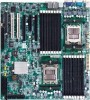
English GA-3CESL3-RH Motherboard 1.2 GA-3CESL3-RH Motherboard Components 1. Processor 1 Socket 2. Processor 2 Socket 3. NVIDIA 4. 5. ITE IT8716F-S I/O controller 6. XGI Z9s VGA controller 7. Video Memory 8. Marvell 88E1116 GbE 9. Marvell 88E1116 GbE 10. Winbond W83792G - Gigabyte GA-3CESL3-RH | Manual - Page 7
Introduction 39 40 78 9 44 18 6 45 19 20 21 22 23 30 28 32 31 29 25 27 26 11 12 41 5 4 38 14 3 13 1 42 43 36 15 10 35 2 34 37 33 17 16 24 7 - Gigabyte GA-3CESL3-RH | Manual - Page 8
English GA-3CESL3-RH Motherboard Chapter 2 Hardware Installation Process 2-1: grease on the processor before placing cooling fan. 4. Please make sure the CPU type is supported by the motherboard. 5. If you do not match the CPU socket Pin 1 and CPU metal lever back into locked position. 3 1 2 8 - Gigabyte GA-3CESL3-RH | Manual - Page 9
the metal bracket into retention Module. Step 2 Hook the other side of metal bracket into retention module. Step 3 Push down the clip to the locked position. Step 4 Connect processor fan can cable to the processor fan connector. 1 3 2 4 9 - Gigabyte GA-3CESL3-RH | Manual - Page 10
English GA-3CESL3-RH Motherboard 2-2: Install Memory Modules Before installing the processor and heatsink, adhere to the following warning: When DIMM LED is ON, do not install/remove DIMM - Gigabyte GA-3CESL3-RH | Manual - Page 11
Hardware Installation Process Installation Step: Step 1 Insert the DIMM memory module vertically into the DIMM slot, and push it down. Step 2 Close the plastic clip at both edges of theDIMM slots to lock the DIMM module. NOTE!! DIMM must be populated in order starting from B1/A1 DIMM sockets. Each - Gigabyte GA-3CESL3-RH | Manual - Page 12
English GA-3CESL3-RH Motherboard DIMM Population Table DIMM: Single or dual Rank Max. capacity 4GB. CPU1 Single Channel (One DIMM) Dual Channel (2 DIMMs) Dual Channel (4 DIMMs) Dual Channel ( - Gigabyte GA-3CESL3-RH | Manual - Page 13
Hardware Installation Process 2-3: Connect ribbon cables, cabinet wires, and power supply 2-3-1 : I/O Back Panel Introduction 13 - Gigabyte GA-3CESL3-RH | Manual - Page 14
English GA-3CESL3-RH Motherboard PS/2 Keyboard and PS/2 Mouse Connector To install a PS/2 port keyboard and mouse, plug the mouse to the upper port (green) and the keyboard - Gigabyte GA-3CESL3-RH | Manual - Page 15
2-4: Connectors Introduction Connector Introduction 16 15 14 5 24 20 7 6 8 11 12 9 23 10 13 17 25 18 4 3 21 22 2 19 1 1. ATX_L1 2. ATX_12V1 3. ATX_12V2 4. IDE1 (IDE cable connector) 5. FDD1 (Floppy cable connector) 6. F_USB1 (Front USB cable connector) 7. F_USB2 (Internal USB cable - Gigabyte GA-3CESL3-RH | Manual - Page 16
English GA-3CESL3-RH Motherboard 1) ATX_L1 (24-pin Auxiliary Power Connector) 24 12 AC power cord should only be connected to your power supply unit after ATX power cable - Gigabyte GA-3CESL3-RH | Manual - Page 17
3 ) ATX_12V2 (4-pin Auxiliary Power Connector) Connector Introduction 13 24 Pin No. 1 2 3 4 Definition GND GND +12V +12V 4 ) IDE (IDE Connector) Please connect first harddisk to IDE1. The red stripe of the ribbon cable must be the same side with the Pin1. 39 40 1 2 17 - Gigabyte GA-3CESL3-RH | Manual - Page 18
English GA-3CESL3-RH Motherboard 5 ) FDD (Floppy Connector) Please connect the floppy drive ribbon cables to FDD. It supports 720K,1.2M,1.44M and 2.88Mbytes floppy disk types. The red stripe of the ribbon cable must be the same side with the Pin1. 21 34 - Gigabyte GA-3CESL3-RH | Manual - Page 19
Connector Introduction 8/ 9/ 10/ 11/ 12/ 13 ) SATA 0~5 (Serial ATA Connectors) You can connect the Serial ATA device to this connector, it provides you high speed transfer rates (3.0 Gb/sec). SATA0 1 Pin No. Definition 1 GND 2 TXP 3 TXN 4 GND 5 RXN 7 6 RXP 7 GND SATA4 SATA1 SATA3 - Gigabyte GA-3CESL3-RH | Manual - Page 20
English GA-3CESL3-RH Motherboard 15 ) F_Panel (2X12 Pins Front Panel connector) Please connect the power LED, PC speaker, reset switch and power switch of your chassis front panel - Gigabyte GA-3CESL3-RH | Manual - Page 21
16 ) GBT_FP1 (2X5 Pins Front Panel connector) Connector Introduction 12 9 10 Pin No. 1. 2. 3. 4. 5. 6. 7. 8. 9. 10. Signal Name HD+ PWLED+ HDPWLEDRST_BTNPWB+ RST_BTN+ PWBNC KEY Description Hard Disk LED Signal anode (+) Power LED Signal anode (+) Hard Disk LED Signal cathode(-) Power LED Signal - Gigabyte GA-3CESL3-RH | Manual - Page 22
English GA-3CESL3-RH Motherboard 17) PS1 (SMBUS connector for power supply) 1 Pin No. Definition 1 SMBus Clock 2 CPU from running under abnormal condition or damaged by overheating.The CPU fan connector supports Max. current up to 1A . 1 1 CPU2_FAN Pin No. 1 2 3 4 Definition GND - Gigabyte GA-3CESL3-RH | Manual - Page 23
Connector Introduction 20 ) MCP55_FAN (North Bridge Chipset Fan Connector) If you install in wrong direction, the Chip Fan will not work. Sometimes will damage the Chip Fan. (Usually black cable is GND) 1 Pin No. Definition 1 GND 2 +12V 3 Sense 21/22 ) SYS_FAN1/SYS_FAN2 (System fan cable - Gigabyte GA-3CESL3-RH | Manual - Page 24
English GA-3CESL3-RH Motherboard 23) BATTERY CAUTION Danger of explosion if battery is incorrectly replaced. Replace only with the same or equivalent type recommended by the manufacturer. Dispose of used batteries according to the If you want to erase CMOS... manufacturer's instructions. - Gigabyte GA-3CESL3-RH | Manual - Page 25
24 ) JP1 (BIOS Recovery Jumper) Jumper Setting 1 1-2 Close: Enable BIOS recovery function 1 2-3 Close: Disabe this function (Default setting) 25 - Gigabyte GA-3CESL3-RH | Manual - Page 26
English GA-3CESL3-RH Motherboard 25 ) CLR_CMOS1 (Clear CMOS Jumper) You may clear the CMOS data to restore its default values by this jumper. Default value doesn't include the " - Gigabyte GA-3CESL3-RH | Manual - Page 27
Chapter 3 BIOS Setup BIOS Setup BIOS Setup is an overview of the BIOS Setup Program. The program that allows users to modify the basic system configuration. This type of information is stored in battery-backed CMOS RAM so that it retains the Setup information when the power is turned off. - Gigabyte GA-3CESL3-RH | Manual - Page 28
GA-3CESL3-RH Motherboard GETTINGHELP Main Menu The on-line description of the highlighted setup function is displayed at the bottom of the screen. Status Page Setup Menu / - Gigabyte GA-3CESL3-RH | Manual - Page 29
BIOS Setup Main Once you enter Phoenix BIOS Setup Utility, the Main Menu (Figure 1) will appear on the screen. Use arrow keys to select among the items and press to accept or enter the sub-menu. Figure 1: Main System Time The time is calculated based on the 24-hour military time clock. Set - Gigabyte GA-3CESL3-RH | Manual - Page 30
GA-3CESL3-RH Motherboard Processor Information These following items display all information of current CPU Type, CPU Speed, and CPU Count. These items are display-only which is determined by POST (Power On Self Test) of the BIOS. Total Memory Size This item identifies the total memory size. 30 - Gigabyte GA-3CESL3-RH | Manual - Page 31
Advanced BIOS Setup About This Section: Advanced With this section, allowing user to configure your system for basic operation. User can change the processor options, chipset configuration, PCI configuration and chipset control. Figure 2: Advanced 31 - Gigabyte GA-3CESL3-RH | Manual - Page 32
GA-3CESL3-RH Motherboard Advanced Processor Options Figure 2-1: Advanced Processor Option 32 - Gigabyte GA-3CESL3-RH | Manual - Page 33
Advanced Processor Option BIOS Setup This category includes the information of CPU Type, CPU Speed, CPU1/CPU2 ID, CPU1/CPU2 L2 Cache, CPU Type, CPU Speed. Setup menu for AMD Virtualization (TM) Technology, Enhanced Virus Protection, Power Now Technology, Node Interleave, and ACPI SRAT Table. AMD - Gigabyte GA-3CESL3-RH | Manual - Page 34
BIOS Setup Optimize Performance Unganged Select Unganged mode as optimize performance. (Default setting) Ganged Select Ganged mode as optimize performance. ECC error reporting Enabled Enable ECC error reporting. (Default setting) Disabled Disable ECC error reporting. 34 - Gigabyte GA-3CESL3-RH | Manual - Page 35
GA-3CESL3-RH Motherboard Memory Configuration Figure 2-2: Memory Configuration Syetem Memory/Extended Memory /DIMM Information These category is display-only which is determined by POST (Power On Self - Gigabyte GA-3CESL3-RH | Manual - Page 36
Advanced Chipset Control BIOS Setup Figure 2-3: Advanced Chipset Control Wake on Keyboard/Mouse This item allows you to set the enable/disable for powering-on the system by keyboard and mouse. Enabled Wake on Keyboard/Mouse. (Default setting) Disabled Disable this function. Note: This item - Gigabyte GA-3CESL3-RH | Manual - Page 37
GA-3CESL3-RH Motherboard Wake On RTC Alarm You can set "RTC" items to enabled and key in Data/time to power on system. Disabled Disable this function. Enabled Enable alarm function to POWER ON system. (Default setting) 37 - Gigabyte GA-3CESL3-RH | Manual - Page 38
PCI Configuration BIOS Setup Figure 2-4: PCI Configuration PCI Slot 1~5 Option ROM Enabled Enable this item to initialize device expansion ROM. (Defualt setting) Disabled Disable this function. Onboard LAN1 Control Enabled Enable onboard LAN1 device. (Defualt setting) Disabled Disable - Gigabyte GA-3CESL3-RH | Manual - Page 39
GA-3CESL3-RH Motherboard Onboard LAN2 Control Enabled Enable onboard LAN1 device. (Defualt setting) Disabled Disable this function. LAN2 Optiona ROM Scan Enabled Enableing this item to initialize - Gigabyte GA-3CESL3-RH | Manual - Page 40
I/O Device Configuration BIOS Setup Figure 2-5: I/O Device Configuration Serial Port A This allows users to configure serial prot A address by using this option. Enabled Set serial port A address to 3F8/IRQ4. Disabled No configuration. Auto Serial Port B Auto-detection. (Default setting) - Gigabyte GA-3CESL3-RH | Manual - Page 41
GA-3CESL3-RH Motherboard PS/2 Mouse Set this option 'Enabled' to allow BIOS support for a PS/2 - type mouse. Enabled 'Enabled' forces the PS/2 mouse port to be enabled regardless if a mouse is present. (Default setting) Disabled 'Disabled' prevents any - Gigabyte GA-3CESL3-RH | Manual - Page 42
GA-3CESL3-RH Motherboard IDE Configuration Figure 2-6: IDE Configuration Primary Master, Slave/SATA0~5 The category identifies the types of hard disk from drive C to F and SATA 0~SATA 5 are - Gigabyte GA-3CESL3-RH | Manual - Page 43
. Auto: The data transfer from and to the device occurs multiple sectors at a time if the device supports it. LBA/Large Mode This field shows if the device type in the specific IDE channel support LBA Mode 32-Bit I/O Enable this function to max imize the IDE data transfer rate. Transfer Mode - Gigabyte GA-3CESL3-RH | Manual - Page 44
GA-3CESL3-RH Motherboard Floppy Configuration Figure 2-7: Floppy Configuration Legacy Diskette A This category identifies the type of floppy disk drive A that has been installed in the computer. Disabled - Gigabyte GA-3CESL3-RH | Manual - Page 45
. (Default setting) Multiprocessor Specification This option allows user to configure the multiprocessor(MP) specification revision level. Some operating system will require 1.1 for compatibility reasons. 1.4 Support MPS Version 1.4 . (Default setting) 1.1 Support M PS Version 1.1. 45 - Gigabyte GA-3CESL3-RH | Manual - Page 46
GA-3CESL3-RH Motherboard Post Error Pause All Errors Whenever the BIOS detects a non-fatal error the system will be stopped. All, But Keyboard The system boot will - Gigabyte GA-3CESL3-RH | Manual - Page 47
DMI Event Logging BIOS Setup Figure 2-9: DMI Event Logging Event log vaildity/Event log capacity These two items display the current status of Event log vaildity and Event log capacity. View DMI event log Press [Enter] to view DMI event log. Event Logging Enabled Select Enabled to allow logging of - Gigabyte GA-3CESL3-RH | Manual - Page 48
GA-3CESL3-RH Motherboard Disabled Disable this function. Mark DMI events as read Press [Enter] to mark all DMI events in the event log as read. Clear all Event Logs Yes Clear all event logs. No Disable this function. (Default setting) 48 - Gigabyte GA-3CESL3-RH | Manual - Page 49
Hardware Monitor BIOS Setup Figure 2-10: Hardware Monitor 49 - Gigabyte GA-3CESL3-RH | Manual - Page 50
GA-3CESL3-RH Motherboard 50 - Gigabyte GA-3CESL3-RH | Manual - Page 51
CPU1/CPU 2/ SystemTemperature BIOS Setup Display the current CPU1/2 temperature and system temperature. Voltage Monitor: VCORE1/2, 3.3V, 5V, -12V, +12V, 1.5V, P1 1.8V, P2 1.8V, P1 0.9V, P2 0.9V Detect system's voltage status automatically. FAN Monitor: CPU1/2 FAN, MCP55 FAN, SYS1/2 FAN Display - Gigabyte GA-3CESL3-RH | Manual - Page 52
GA-3CESL3-RH Motherboard Security * About This Section: Security In this section, user can set either supervisor or user passwords, or both for different level of password securities. - Gigabyte GA-3CESL3-RH | Manual - Page 53
BIOS Setup Set User Password You can only enter but do not have the right to change the options of the setup menus. When you select this function, the following message will appear at the center of the screen to assist you in creating a password. Type the password up to 6 characters in lengh and - Gigabyte GA-3CESL3-RH | Manual - Page 54
GA-3CESL3-RH Motherboard Server Figure 4: Server 54 - Gigabyte GA-3CESL3-RH | Manual - Page 55
System Management BIOS Setup Figure 4-1: System Management Server Management This category allows user to view the server management features. Including information of BIOS Version, System Product Name, System Serial Number, BaseBoard ID, Main Board Serial Number, and, System ID. All items in this - Gigabyte GA-3CESL3-RH | Manual - Page 56
GA-3CESL3-RH Motherboard Console Redirection Figure 4-2: Remote Access Configuration COM Port Adress If this option is set to enabled, it will use a port on the motherboard. On- - Gigabyte GA-3CESL3-RH | Manual - Page 57
Flow Control This option provide user to enable the flow control function. None Not supported. XON/OFF Software control. CTS/RTS Hardware control. (Default setting) BIOS Setup Continue C.R. after POST This option allows user to enable console redirection after O.S has - Gigabyte GA-3CESL3-RH | Manual - Page 58
GA-3CESL3-RH Motherboard Boot Figure 5: Boot Boot Device Priority This field determines which type of device the system attempt to boot from after BIOS POST completed. Specifies - Gigabyte GA-3CESL3-RH | Manual - Page 59
Exit BIOS Setup Figure 6: Exit * About This Section: Exit Once you have made the changes in the BIOS setup items, you have to save your changes and exit BIOS setup program. Select "Exit" from the menu bar, to display the following sub-menu. Save Changes and Exit Discard Changes and Exit Discard - Gigabyte GA-3CESL3-RH | Manual - Page 60
GA-3CESL3-RH Motherboard Exit Saving Changes This option allows user to exit system setup with saving the changes. Press on this item to ask for the - Gigabyte GA-3CESL3-RH | Manual - Page 61
BIOS Setup Exit Discarding Changes This option allows user to exit system setup without changing any previous settings values in CMOS. The previous selection remain in effect. This will exit the Setup Utility and restart your compuetr when selecting this option. 61 - Gigabyte GA-3CESL3-RH | Manual - Page 62
GA-3CESL3-RH Motherboard Load Setup Default This option allows user to load default values for all setup items. When you press on this item, you will get a confirmation dialog box with a message as below: 62 - Gigabyte GA-3CESL3-RH | Manual - Page 63
BIOS Setup Discard Changes This option allows user to exit system setup without changing any previous settings values in CMOS. The previous selection remain in effect. This will exit the Setup Utility and restart your compuetr when selecting this option. 63 - Gigabyte GA-3CESL3-RH | Manual - Page 64
GA-3CESL3-RH Motherboard Save Changes This option allows user to save setup dat ato CMOS. When you press on this item, you will get a confirmation dialog box with a message as below: Press [Yes] to save setup daya to CMOS. 64
-
 1
1 -
 2
2 -
 3
3 -
 4
4 -
 5
5 -
 6
6 -
 7
7 -
8
-
9
-
10
-
11
-
12
-
13
-
14
-
15
-
16
-
17
-
18
-
19
-
20
-
21
-
22
-
23
-
24
-
25
-
26
-
27
-
28
-
29
-
30
-
31
-
32
-
33
-
34
-
35
-
36
-
37
-
38
-
39
-
40
-
41
-
42
-
43
-
44
-
45
-
46
-
47
-
48
-
49
-
50
-
51
-
52
-
53
-
54
-
55
-
56
-
57
-
58
-
59
-
60
-
61
-
62
-
63
-
64
 |
 |

USER’S MANUAL
GA-3CESL3-RH
AMD Socket F Dual Processor Motherboard
AMD Opteron
™
Socket F Dual Processor Motherboard
Rev. 1601
*
The WEEE marking on the product indicates this product must not be disposed of with
user's other household waste and must be handed over to a designated collection point
for the recycling of waste electrical and electronic equipment!!
*
The WEEE marking applies only in European Union's member states.