Gigabyte GA-6KIEL-RH Manual
Gigabyte GA-6KIEL-RH Manual
 |
View all Gigabyte GA-6KIEL-RH manuals
Add to My Manuals
Save this manual to your list of manuals |
Gigabyte GA-6KIEL-RH manual content summary:
- Gigabyte GA-6KIEL-RH | Manual - Page 1
GA-6KIEH-RH GA-6KIEH2-RH GA-6KIEL-RH Intel® mini-ITX Motherboard USER'S MANUAL Intel® mini-ITX Motherboard Rev. 1201 * The WEEE marking on the product indicates this product must not be disposed of with user's other household waste - Gigabyte GA-6KIEL-RH | Manual - Page 2
GA-6KIEH-RH/GA-6KIEH2-RH/GA-6KIEL-RH Motherboard Copyright © 2007 GIGA-BYTE TECHNOLOGY CO., LTD. All rights reserved. The trademarks mentioned in the manual are legally registered to their respective companies. Notice The written content provided with this product is the property of Gigabyte. No - Gigabyte GA-6KIEL-RH | Manual - Page 3
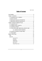
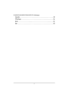
Memory Modules 13 2-4: Connect ribbon cables, cabinet wires, and power supply 15 2-4-1 : I/O Back Panel Introduction (GA-6KIEH-RH 15 2-4-2 : I/O Back Panel Introduction (GA-6KIEL-RH 16 2-5: Connectors Introduction & Jumper Setting 20 2-6: Block Diagram 27 Chapter 3 BIOS Setup 28 Main ...30 - Gigabyte GA-6KIEL-RH | Manual - Page 4
GA-6KIEH-RH/GA-6KIEH2-RH/GA-6KIEL-RH Motherboard Security ...49 TPM State 51 Boot ...52 Exit ...53 4 - Gigabyte GA-6KIEL-RH | Manual - Page 5
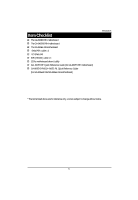
Shield Kit IDE (ATA100 ) cable x 1 CD for motherboard driver & utility GA--6KIEH-RH Quick Reference Guide (for GA-6KIEH-RH motherboard) GA-6KIEH2-RH/GA--6KIEL-RL Quick Reference Guide (for GA-6KIEH2-RH/GA-6KIEL-RH motherboard) Introduction * The items listed above are for reference only, and are - Gigabyte GA-6KIEL-RH | Manual - Page 6
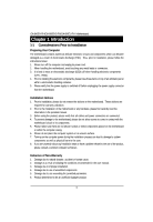
GA-6KIEH-RH/GA-6KIEH2-RH/GA-6KIEL-RH installation, please follow the instructions below: 1. Please turn information in the provided manual. 3. Before using the any installation steps or have a problem related to the use of the conditions recommended in the user manual. 3. Damage due to improper - Gigabyte GA-6KIEL-RH | Manual - Page 7
Introduction 1.2 Features Summary Form Factor CPU y 170mm x 170mm Mini ITX form factor, 8 layers PCB. y Supports single Intel® Merom/Penryn/Celeron M550 series (GA-6KIEH-RH) CPU (GA-6KIEL-RH) Chipset (GA-6KIEH-RH) processor y Socket P with 533/800MHz y Supports single Intel® Celeron M550 series - Gigabyte GA-6KIEL-RH | Manual - Page 8
CPU/Power/System Fan Revolution Detect y CPU shutdown when overheat On-Board LAN y Intel® 82566DC and 82573L GbE controllers (GA-6KIEH-RH) y Intel® 82566DC GbE controller (GA-6KIEL-RH) y Supports WOL, PXE BIOS y Phoenix BIOS on 8Mb SPI Flash ROM Additional Features y External Modem wake up - Gigabyte GA-6KIEL-RH | Manual - Page 9
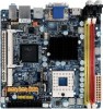
Introduction 1.3 Motherboard Components (GA-6KIEH-RH) Audio jack Relteak ALC883 USB USB LAN LAN COM1 F_AUDIO1 Intel 82566DC GbE PCI 32/33MHz Mini PCI Intel ICH8M COM2 VGA DVI-D HDMI Intel - Gigabyte GA-6KIEL-RH | Manual - Page 10
GA-6KIEH-RH/GA-6KIEH2-RH/GA-6KIEL-RH Motherboard 1.4 Motherboard Components (GA-6KIEH2-RH/GA-6KIEL-RH) Relteak ALC883 USB USB LAN COM1 F_AUDIO1 Intel 82566DC GbE PCI 32/33MHz Mini PCI Intel ICH8M COM2 VGA DVI-D HDMI Silicon Image SiI1392 Intel GME965 (6KIEH2) Intel GLE960 (6KIEL) DDRII - Gigabyte GA-6KIEL-RH | Manual - Page 11
Hardware Installation Process Chapter 2 Hardware Installation Process 2-1: Installing Processor Step 1 Step 2 The processor socket come with a screw to secure the processor. Insert the CPU into the socket by making sure the notch on the corner of the CPUcorresponds with the notch on the inside of - Gigabyte GA-6KIEL-RH | Manual - Page 12
GA-6KIEH-RH/GA-6KIEH2-RH/GA-6KIEL-RH Motherboard 2-2: Installing Processor Colling Fan WARNING! ! To prevent the CPU overheat, please make sure you have apply the CPU cooler paste on the surface of - Gigabyte GA-6KIEL-RH | Manual - Page 13
with the following conditions: 1. Please make sure the computer power is switched off before installing or removing memory modules. The motherboard supports DDR2 memory module, whereby BIOS will automatically detect memory capacity and specifications. The memory module only can be inserted in one - Gigabyte GA-6KIEL-RH | Manual - Page 14
GA-6KIEH-RH/GA-6KIEH2-RH/GA-6KIEL-RH Motherboard Table 1. Supported DIMM Module Type (GA-6KIEH-RH) Size 256MB 512MB 1GB 2GB Organization 8MB x 8 x 4 bks 16MB x 16 x 4bks 16MB x 8 x 4bks 32MB x 16 x 4bks 32MB x 8 x 4bks 64MB x 16 x 4bks 32MB x 8 x 4bks 64MB x 16 x - Gigabyte GA-6KIEL-RH | Manual - Page 15
Hardware Installation Process 2-4: Connect ribbon cables, cabinet wires, and power supply 2-4-1 : I/O Back Panel Introduction (GA-6KIEH-RH) 15 - Gigabyte GA-6KIEL-RH | Manual - Page 16
GA-6KIEH-RH/GA-6KIEH2-RH/GA-6KIEL-RH Motherboard 2-4-2 : I/O Back Panel Introduction (GA-6KIEH2-RH/GA-6KIEL-RH) 16 - Gigabyte GA-6KIEL-RH | Manual - Page 17
.), and enter BIOS Setup, then set Onboard VGA output connect to D-SUB/ HDMI under Advanced BIOS Features. Please note the HDMI audio output only supports AC3, DTS and 2-channel-LPCM formats. (AC3 and DTS require the use of an external decoder for decoding.) In Windows XP, select Start>Control - Gigabyte GA-6KIEL-RH | Manual - Page 18
GA-6KIEH-RH/GA-6KIEH2-RH/GA-6KIEL-RH Motherboard In Windows Vista, select Start>Control Panel>Sound, select Realtek HDMI Output and then click Set Default. VGA Port Connect the monitor cable to this port. DVI-D Port The DVI-D port supports DVI-D specifictation. Connect a monitor that supports DVI-D - Gigabyte GA-6KIEL-RH | Manual - Page 19
LAN LED Description LED2 (Green/Yellow) Hardware Installation Process LED1 (Green) Name LED1 LED2 Color Green Green Green Green Yellow Yellow Condition ON BLINK OFF OFF OFF ON BLINK ON BLINK Description LAN Link / no Access LAN Access Idle 10Mbps connection Port identification with 10 Mbps - Gigabyte GA-6KIEL-RH | Manual - Page 20
GA-6KIEH-RH/GA-6KIEH2-RH/GA-6KIEL-RH Motherboard 2-5: Connectors Introduction & Jumper Setting 8 12 9 4 3 17 13 16 1 15 7 10 11 5 6 2 14 1. ATX1 12. F_AUDIO1 2. ) 8. COM1 9. COM2 10. F_USB1 (Fornt USB cable connector) 11. F_USB2 (Fornt USB cable connector) ** For GA-6KIEH-RH Only 20 - Gigabyte GA-6KIEL-RH | Manual - Page 21
connect two IDE devices, please set the jumper on one IDE device as Master and the other as Slave (for information, please refer to the instructions located on the IDE device). Before attaching the IDE cable, please take note of the foolproof groove in IDE connector. 39 1 40 2 21 - Gigabyte GA-6KIEL-RH | Manual - Page 22
GA-6KIEH-RH/GA-6KIEH2-RH/GA-6KIEL-RH Motherboard 3/ 4/ 5/ 6/ 7 ) SATA 1~5 (Serial ATA cable connectors) SATA 1 Pin No. 1 2 3 4 5 6 7 Definition GND TXP TXN GND RXN RXP GND SATA5 SATA2 SATA1 ** For GA-6KIEH-RH Only 8/ 9 ) COM1/COM2 COM1 COM2 SATA3** SATA4** 91 10 9 10 2 21 Pin No. 1 2 3 4 - Gigabyte GA-6KIEL-RH | Manual - Page 23
pin assigment on the cable is the same as the pin assigment on the MB header. To find out if the chassis you are buying support front audio connector, please contact your dealer. 91 10 2 Pin No. 1 2 3 4 5 6 7 8 9 10 Definition MIC_L GND MIC_R -ACZ_DEC Line_R GND Faudio_JD No Pin Line_L GND 23 - Gigabyte GA-6KIEL-RH | Manual - Page 24
GA-6KIEH-RH/GA-6KIEH2-RH/GA-6KIEL-RH Motherboard 13 ) BAT1 (Battery) CAUTION Danger of explosion if battery is incorrectly replaced. Replace only with the same or equivalent type recommended by the manufacturer. Dispose of used batteries according to the manufacturer's instructions positive - Gigabyte GA-6KIEL-RH | Manual - Page 25
Connector Introduction 16 ) F_Panel (2X10 Pins Front Panel connector) Please connect the power LED, PC speaker, reset switch and power switch of your chassis front panel to the F_PANEL connector according to the pin assignment above. 20 19 21 Pin No. 1. 2. 3. 4. 5. 6. 7. 8. 9. 10. 11. 12. 13. 14. - Gigabyte GA-6KIEL-RH | Manual - Page 26
GA-6KIEH-RH/GA-6KIEH2-RH/GA-6KIEL-RH Motherboard 17 ) CLR_CMOS1 (Clear CMOS Function) You may clear the CMOS data to restore its default values by this jumper. Default value doesn't include the " - Gigabyte GA-6KIEL-RH | Manual - Page 27
2-6: Block Diagram HDMI DVI Pb Pr SPDIF Y RJ45 USB2 USB3 VGA Connector Silicon Image SiI1392 SDVO TV Out RJ45 USB0 USB1 CPU Intel Merom HOST BUS NB Intel GME965 Clock Generator ICS ICS9LP505 Block Diagram 533/667 DDR2 SDRAM 533/667 DDR2 SDRAM PCI 32/33MHz slot LPC USB2.0 LAN LAN Inel Inel - Gigabyte GA-6KIEL-RH | Manual - Page 28
GA-6KIEH-RH/GA-6KIEL-RH Motherboard Chapter 3 BIOS Setup BIOS (Basic Input and Output System) includes a CMOS SETUP utility which allows user to configure required settings or to activate certain - Gigabyte GA-6KIEL-RH | Manual - Page 29
GETTINGHELP BIOS Setup Main Menu The on-line description of the highlighted setup function is displayed at the bottom of the screen. Status Page Setup Menu / Option Page Setup Menu Press F1 to pop up a small help window that describes the appropriate keys to use and the possible selections for - Gigabyte GA-6KIEL-RH | Manual - Page 30
GA-6KIEH-RH/GA-6KIEL-RH Motherboard Main Once you enter Phoenix BIOS Setup Utility, the Main Menu (Figure 1) will appear on the screen. Use arrow keys to select among the - Gigabyte GA-6KIEL-RH | Manual - Page 31
. Auto: The data transfer from and to the device occurs multiple sectors at a time if the device supports it. LBA Mode This field shows if the device type in the specific IDE channel support LBA Mode. 32-Bit I/O Enable this function to max imize the IDE data transfer rate. Transfer Mode This - Gigabyte GA-6KIEL-RH | Manual - Page 32
GA-6KIEH-RH/GA-6KIEL-RH Motherboard installed Halt On The category determines whether the computer will stop if an error is detected during power up. No Errors The system boot - Gigabyte GA-6KIEL-RH | Manual - Page 33
BIOS Setup Advanced About This Section: Advanced With this section, allowing user to configure your system for advanced operation. User can set the CPU Features, GM965 Features, ICH8MD0 Features, Super I/O Features, Power Features and Hardware Monitor Features. Figure 2: Advanced 33 - Gigabyte GA-6KIEL-RH | Manual - Page 34
GA-6KIEH-RH/GA-6KIEL-RH Motherboard System Information Figure 2-1: System Information System Information This category includes the information of BIOS Version, Product Name, BIOS Build Date, CPU Type, CPU Speed, - Gigabyte GA-6KIEL-RH | Manual - Page 35
CPU Feature BIOS Setup Figure 2-2: CPU Feature Manufacturer This item displays the information of original CPU manufacturer. CPU Type This item displays the information of installed CPU type. CPU Speed This item displays the information of CPU speed. CPU L2 Cache Enabled Enable CPU L2 - Gigabyte GA-6KIEL-RH | Manual - Page 36
GA-6KIEH-RH/GA-6KIEL-RH Motherboard Thermal Control Circuit Configure the thermal control circuit portion of thermal monitor features of the processor. Disabled Disable thermal control circuit function. TM1 Select - Gigabyte GA-6KIEL-RH | Manual - Page 37
GM965 Feature BIOS Setup Figure 2-3: GM965 Feature IGD Boot Type Select the Video Device that will be actived during POST. Options VBT Default, CRT, TV, EFP, CRT+EFP. IGDDevice 2 Enable or disable the Internal Graphics Device by setting this item to desire value. Auto Enable internal - Gigabyte GA-6KIEL-RH | Manual - Page 38
GA-6KIEH-RH/GA-6KIEL-RH Motherboard Pre-Allocated Memory Size Select the amount of Pre-Allocated Graphics Memory for use by the internal grapphics device. 8M Select 8M as Pre- - Gigabyte GA-6KIEL-RH | Manual - Page 39
ICH8MDO Feature BIOS Setup Figure 2-4: ICH8MDO Feature ICH8M Sata Pata Control Sub-Menu Press [Enter] to configure advanced sub-menu for ICH8M Sata Pata Control options. ACHI Configuration Enabled Enable ACHI Configuration. Disabled Disable ACHI Configuration.(Defualt setting) Native Mode - Gigabyte GA-6KIEL-RH | Manual - Page 40
GA-6KIEH-RH/GA-6KIEL-RH Motherboard DFOROM (Robson) Support Set this item to enabled will reduce the time it takes for a system to power up, access programs, and write data to the hard drive . Enabled Enable DFOROM (Robson) Support. Disabled Disable DFOROM (Robson) Support. (Default setting) Please - Gigabyte GA-6KIEL-RH | Manual - Page 41
onboard LAN2 controller function. (Default setting) Disabled Disable onboard LAN2 controller function. BIOS Setup This item will show up only for GA-6KIEH-RH. LAN2 PXE OPROM Enabled Enable onboard LAN2 PXE option ROM. (Default setting) Disabled Disable onboard LAN2 PXE option ROM. This item - Gigabyte GA-6KIEL-RH | Manual - Page 42
GA-6KIEH-RH/GA-6KIEL-RH Motherboard Super I/O Feature Figure 2-5:Super I/O Feature Serial Port A This allows users to configure serial prot A by using this option. Enabled Disabled Enable the configuration (Default - Gigabyte GA-6KIEL-RH | Manual - Page 43
VT100 8bit, PC-ANSI 7bit, VT100+, VT-UTF8 Flow Control This option provide user to enable the flow control function. None Not supported. XON/OFF Software control. CTS/RTS Hardware control. (Default setting) Console Connection This field indicates whether the console is connected directly to - Gigabyte GA-6KIEL-RH | Manual - Page 44
GA-6KIEH-RH/GA-6KIEL-RH Motherboard Disabled Console is connected via the modem. Continue C.R. after POST This option allows user to enable console redirection after O.S has loaded. On Enable console redirection after O.S has loaded. Off Disable this function. (Default setting) 44 - Gigabyte GA-6KIEL-RH | Manual - Page 45
Power Feature BIOS Setup Figure 2-6: Power Feature Disable ACPI Six Set the ACPI power state for your system. None Disable this function. (Default setting) S1 Set ACPI suspend type to S1 (Power On Suspend). S3 Set ACPI suspend type to S3(Suspend To RAM). Soft-Off by PWR Instant-Off Press - Gigabyte GA-6KIEL-RH | Manual - Page 46
GA-6KIEH-RH/GA-6KIEL-RH Motherboard Power On System power state when AC cord is re-plugged. Wake Up by PME Enabled Enable PME as wake up function. (Default setting) - Gigabyte GA-6KIEL-RH | Manual - Page 47
Hardware Monitor Feature BIOS Setup Figure 2-7: Hardware Monitor Feature System Temperature/CPU Temperature Detects and displays current system and CPU temperature automatically. CPU Fan1/CASE Fan 2 Detects and displays the current CPU/system fan speed status automatically CPU Vcore/P 1VB/3VDual/ - Gigabyte GA-6KIEL-RH | Manual - Page 48
GA-6KIEH-RH/GA-6KIEL-RH Motherboard Quick Boot Mode Set this item to enable will allow to skip sertain tests suring booting. This will decrease the time needed to boot - Gigabyte GA-6KIEL-RH | Manual - Page 49
Security BIOS Setup About This Section: Security In this section, user can set either supervisor or user passwords, or both for different level of password securities. In addition, user also can set the virus protection for boot sector. Figure 3: Security Set Supervisor Password You can install - Gigabyte GA-6KIEL-RH | Manual - Page 50
GA-6KIEH-RH/GA-6KIEL-RH Motherboard Type the password up to 6 characters in lengh and press - Gigabyte GA-6KIEL-RH | Manual - Page 51
TPM State BIOS Setup Figure 4: TPM State Current TPM State Displays the current TPM State status. Change TPM State No Change No configuration on TPM State. (Default setting) Enable & Activate Enable and activate TPM State. Deactivate & Disable Disable and deactivate TPM State. Clear Clear - Gigabyte GA-6KIEL-RH | Manual - Page 52
GA-6KIEH-RH/GA-6KIEL-RH Motherboard Boot Figure 5: Boot Boot Priority Order This field determines which type of device the system attempt to boot from after PhoenixBIOS Post completed. Specifies - Gigabyte GA-6KIEL-RH | Manual - Page 53
Exit BIOS Setup Figure 6: Exit About This Section: Exit Once you have changed all of the set values in the BIOS setup menu, you should save your changes and exit BIOS setup program. Select "Exit" from the menu bar, to display the following sub-menu. Exit Saving Changes Exit Discarding Changes Load - Gigabyte GA-6KIEL-RH | Manual - Page 54
GA-6KIEH-RH/GA-6KIEL-RH Motherboard Exit Saving Changes This option allows user to exit system setup with saving the changes. Press on this item to ask for the - Gigabyte GA-6KIEL-RH | Manual - Page 55
BIOS Setup Exit Discarding Changes This option allows user to exit system setup without changing any previous settings values in CMOS. The previous selection remain in effect. This will exit the Setup Utility and restart your compuetr when selecting this option. 55 - Gigabyte GA-6KIEL-RH | Manual - Page 56
GA-6KIEH-RH/GA-6KIEL-RH Motherboard &Load Settup Default This option allows user to load default values for all setup items. When you press on this item, you will get a confirmation dialog box with a message as below: 56 - Gigabyte GA-6KIEL-RH | Manual - Page 57
BIOS Setup Discard Changes This option allows user to load previos values from CMOS for all setup item. When you press on this item, you will get a confirmation dialog box with a message as below: 57 - Gigabyte GA-6KIEL-RH | Manual - Page 58
GA-6KIEH-RH/GA-6KIEL-RH Motherboard Save Changes This option allows user to save setup dat ato CMOS. When you press on this item, you will get a confirmation dialog box with a message as below: Press [Yes] to save setup daya to CMOS. 58
-
 1
1 -
 2
2 -
 3
3 -
 4
4 -
 5
5 -
 6
6 -
 7
7 -
8
-
9
-
10
-
11
-
12
-
13
-
14
-
15
-
16
-
17
-
18
-
19
-
20
-
21
-
22
-
23
-
24
-
25
-
26
-
27
-
28
-
29
-
30
-
31
-
32
-
33
-
34
-
35
-
36
-
37
-
38
-
39
-
40
-
41
-
42
-
43
-
44
-
45
-
46
-
47
-
48
-
49
-
50
-
51
-
52
-
53
-
54
-
55
-
56
-
57
-
58
 |
 |

USER’S MANUAL
GA-6KIEH-RH
GA-6KIEH2-RH
GA-6KIEL-RH
Intel
®
mini-ITX Motherboard
Intel
®
mini-ITX Motherboard
Rev. 1201
*
The WEEE marking on the product indicates this product must not be disposed of with
user's other household waste and must be handed over to a designated collection point
for the recycling of waste electrical and electronic equipment!!
*
The WEEE marking applies only in European Union's member states.