Gigabyte GA-6PXSVT Manual
Gigabyte GA-6PXSVT Manual
 |
View all Gigabyte GA-6PXSVT manuals
Add to My Manuals
Save this manual to your list of manuals |
Gigabyte GA-6PXSVT manual content summary:
- Gigabyte GA-6PXSVT | Manual - Page 1
GA-6PXSVT LGA 2011 socket motherboard for Intel® E5-1600/E5-2600 series processors User's Manual Rev. 1001 - Gigabyte GA-6PXSVT | Manual - Page 2
respective owners. Disclaimer Information in this manual is protected by copyright laws and is the property of GIGABYTE. Changes to the specifications and features in this manual may be made by GIGABYTE without prior notice. No part of this manual may be reproduced, copied, translated, transmitted - Gigabyte GA-6PXSVT | Manual - Page 3
Table of Contents Box Contents...5 GA-6PXSVT Motherboard Layout 6 GA-6PVXT Block Diagram 9 Chapter 1 Hardware Installation 10 1-1 Installation Precautions 10 1-2 Product Specifications 11 1-3 Installing the CPU and CPU Cooler 13 1-3-1 Installing the CPU...13 1-4 Installing - Gigabyte GA-6PXSVT | Manual - Page 4
2-3-3 Intel ME Subsystem 73 2-4 Security Menu 74 2-5 Boot Menu...75 2-5-1 CSM16 Parameters 77 2-5-2 CSM Parameters ...78 2-6 Exit Menu...80 Chapter 3 Appendix...81 3-1 Regulatory Statements 81 - 4 - - Gigabyte GA-6PXSVT | Manual - Page 5
Box Contents GA-6PXSVT motherboard Driver CD Two SATA cables I/O Shield • The box contents above are for reference only and the actual items shall depend on the product package you obtain. The box contents are subject to change without notice. • The motherboard image is for reference only. - 5 - - Gigabyte GA-6PXSVT | Manual - Page 6
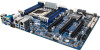
GA-6PXSVT Motherboard Layout 49 50 1 2 3 45 48 47 44 46 53 54 52 55 51 43 42 41 40 43 39 56 57 17 18 19 20 38 27 33 32 31 25 37 34 28 26 7 4 5 6 8 9 16 10 11 12 13 15 14 36 35 30 29 24 23 22 21 - 6 - - Gigabyte GA-6PXSVT | Manual - Page 7
power connector System fan #3 connector System fan #1connector System fan #2 connector SATA SGPIO header SATA port 1 DOM support jumper BIOS Upgrade ROM SATA port 0 DOM support jumper SATA 6Gb/s connectors SATA 3Gb/s connectors Battery socket Chassis intrusion jumper Clear CMOS jumper Clear password - Gigabyte GA-6PXSVT | Manual - Page 8
to 2-3 pins (Default setting), in order to reduce any risk of hard disk damage. Please refer to Page 35 for SATA_DOM0 and SATA_DOM1 jumper setting instruction. - 8 - - Gigabyte GA-6PXSVT | Manual - Page 9
GA-6PVXT Block Diagram - 9 - - Gigabyte GA-6PXSVT | Manual - Page 10
electrostatic discharge (ESD). Prior to installation, carefully read the user's manual and follow these procedures: • Prior to installation, do not remove are uncertain about any installation steps or have a problem related to the use of the product, please consult a certified computer technician. - Gigabyte GA-6PXSVT | Manual - Page 11
the PCIE_2 slot will operate at x8 mode.) 10 x SATA 6Gb/s connectors (SATA_0_1/SATA6/7/8/9/10/11/12/13) 4 x SATA 3Gb/s connectors (SATA_2_3/SATA_4_5) Support for Intel RSTe SATA RAID 0, RAID 1, RAID 10, RAID 5 4 x USB 2.0 ports (2 via the USB brackets connected to the internal USB headers/2 at back - Gigabyte GA-6PXSVT | Manual - Page 12
/System/Power fan fail warning ŠŠ CPU/System fan speed control ŠŠ 1 x 64 Mbit flash ŠŠ AMI BIOS ŠŠ ATX Form Factor; 12 inch x 9.6 inch * GIGABYTE reserves the right to make any changes to the product specifications and product-related information without prior notice. Hardware Installation - 12 - - Gigabyte GA-6PXSVT | Manual - Page 13
1-3 Installing the CPU and CPU Cooler Read the following guidelines before you begin to install the CPU: • Make sure that the motherboard supports the CPU. • Always turn off the computer and unplug the power cord from the power outlet before installing the CPU to prevent hardware damage. • Locate - Gigabyte GA-6PXSVT | Manual - Page 14
B. Follow the steps below to correctly install the CPU into the motherboard CPU socket. •• Before installing the CPU, make sure to turn off the computer and unplug the power cord from the power outlet to prevent damage to the CPU. •• To protect the socket contacts, do not remove the protective - Gigabyte GA-6PXSVT | Manual - Page 15
you are unable to insert the memory, switch the direction. 1-4-1 Four Channel Memory Configuration This motherboard provides eight DDR3 memory sockets and supports Four Channel Technology. After the memory is installed, the BIOS will automatically detect the specifications and capacity of the memory - Gigabyte GA-6PXSVT | Manual - Page 16
1-4-2 Installing a Memory Before installing a memory module, make sure to turn off the computer and unplug the power cord from the power outlet to prevent damage to the memory module. Be sure to install DDR3 DIMMs on this motherboard. Installation Step: Step 1. Insert the DIMM memory module - Gigabyte GA-6PXSVT | Manual - Page 17
port provides Internet connection at up to 1 Gbps data rate. The following describes the states of the LAN port LEDs. USB 3.0 Port The USB port supports the USB 3.0 specification. Use this port for USB devices such as a USB keyboard/mouse, USB printer, USB flash drive and etc. ID Switch Button This - Gigabyte GA-6PXSVT | Manual - Page 18
Speed LED Link Activity LED 10/100/1000 LAN Port 82574 Speed LED: Link/Activity LED: State Yellow On Yellow Blink Green On Green Blink Off Description 1 Gbps data rate Identify 1 Gbps data rate 100 Mbps data rate Identify 100 Mbps data rate 10 Mbps data rate State Description On Link - Gigabyte GA-6PXSVT | Manual - Page 19
1-6 Internal Connectors 20 27 7 3 1 19 18 13 28 29 8 30 17 16 32 31 12 26 11 23 25 22 21 15 24 33 34 14 10 96 45 2 1) ATX1 2) P1_CPU 3) CPU_FAN1 (CPU Fan) 4) SYS_FAN1 (System Fan) 5) SYS_FAN3 (System Fan) 6) SYS_FAN2 (System Fan) 7) SYS_FAN4 (System Fan) 8) PWR_DET1 (PMBus) - Gigabyte GA-6PXSVT | Manual - Page 20
Read the following guidelines before connecting external devices: • First make sure your devices are compliant with the connectors you wish to connect. • Before installing the devices, be sure to turn off the devices and your computer. Unplug the power cord from the power outlet to prevent damage to - Gigabyte GA-6PXSVT | Manual - Page 21
1/2) ATX1/P1_CPU (2x12 Main Power Connector and 2x4 12V Power Connector) With the use of the power connector, the power supply can supply enough stable power to all the components on the motherboard. Before connecting the power connector, first make sure the power supply is turned off and all - Gigabyte GA-6PXSVT | Manual - Page 22
design. When connecting a fan cable, be sure to connect it in the correct orientation (the black connector wire is the ground wire). The motherboard supports CPU fan speed control, which requires the use of a CPU fan with fan speed control design. For optimum heat dissipation, it is recommended that - Gigabyte GA-6PXSVT | Manual - Page 23
/s Connectors) The SATA connectors conform to SATA 6Gb/s standard and are compatible with SATA 3Gb/s and 1.5Gb/s standard. Each SATA connector supports a single SATA device. When SATA_DOM0/1 jumper are set to 2-3 pin: Pin No. Definition 1 GND 7 1 2 TXP 3 TXN 7 1 4 GND SATA01 5 RXN 6 RXP - Gigabyte GA-6PXSVT | Manual - Page 24
6Gb/s Connectors) The SATA connectors conform to SATA 6Gb/s standard and are compatible with SATA 3Gb/s and 1.5Gb/s standard. Each SATA connector supports a single SATA device. 77 SATA12 11 SATA11 SATA13 Pin No. 1 2 3 4 5 6 7 Definition GND TXP TXN GND RXN RXP GND SATA10 DEBUGDEBUG PORT - Gigabyte GA-6PXSVT | Manual - Page 25
14) F_PANEL1 (Front Panel Header) Connect the power switch, reset switch, chassis intrusion switch/sensor and system status indicator on the chassis to this header according to the pin assignments below. Note the positive and negative pins before connecting the cables. 2 24 1 23 Pin No. 1 2 3 4 - Gigabyte GA-6PXSVT | Manual - Page 26
15) BP_1 (HDD Back Plane Board Hearders) 26 25 21 Pin No. 1 2 3 4 5 6 7 8 9 10 11 12 13 14 15 16 17 18 19 20 21 22 23 24 25 26 Definition B_SGCLK PCH_BMC_THROTTLE_N B_SGLD IRQ_FAB_12V_GATE_N_BUF B_SGDOUT GND KEY RresetL_BRB GND BP_ALED_N BP_LED_G_N GND B_SGDIN ASSESS#_LED_BPB GND SMB_BPB1_DATA - Gigabyte GA-6PXSVT | Manual - Page 27
16) F_USB3_1 (USB 3.0 Header) The headers conform to USB 3.0 specification. Each USB header can provide two USB ports via an optional USB bracket. For purchasing the optional USB bracket, please contact the local dealer. 10 11 1 20 G.QBOFM Pin No. 1 2 3 4 5 6 7 8 9 10 11 12 13 14 15 16 17 18 19 20 - Gigabyte GA-6PXSVT | Manual - Page 28
18) COM2 (Serial Port Header) The COM header can provide one serial port via an optional COM port cable. For purchasing the optional COM port cable, please contact the local dealer. Pin No. Definition 12 1 NDCD- 2 NDSR- 3 NSIN 4 NRST- 5 NSOUT 6 NCTS- 9 10 7 NDTR- 8 NRI 9 GND 10 No Pin - Gigabyte GA-6PXSVT | Manual - Page 29
20) BMC_LED1 (BMC Firmware Readiness LED) State Description On BMC firmware is initial Blinking BMC firmware is ready Off System is powered off 21) SATA_SGPIO (SATA SGPIO Header) SGPIO stands for Serial General Purpose Input/Output which is a 4-signal (or 4-wire) bus used between a Host Bus - Gigabyte GA-6PXSVT | Manual - Page 30
do so may cause damage to the motherboard. • After system restart, go to BIOS Setup Exit menu and load factory defaults (select Restore Defaults) or manually configure the BIOS settings (refer to Chapter 2, "BIOS Setup," for BIOS configurations). Hardware Installation - 30 - - Gigabyte GA-6PXSVT | Manual - Page 31
24) PASSWORD1 (Clearing Supervisor Password Jumper) 1 1-2 Close: Normal operation. (Default setting) 1 2-3 Close: Clear supervisor password. 25) CASE_OPEN1 (Case open intrusion header) Open: Active chassis intrustion alert. Closed: Normal operation. Hardware Installation - 31 - - Gigabyte GA-6PXSVT | Manual - Page 32
26) BIOS_RCVR (BIOS Recovery Jumper) 1 1-2 Close: Normal operation. (Default setting) 1 2-3 Close: BIOS recovery mode. 27) SSB_ME1 (ME Recovery Jumper) 1 1-2 Close: Enable ME recovery. 1 2-3 Close: Disable ME recovery. (Default setting) - 32 - Hardware Installation - Gigabyte GA-6PXSVT | Manual - Page 33
28) PMBUS_SEL (PMBus Power Select Jumper) 1 1-2 Close: PMBus connects to PCH. 1 2-3 Close: PMBus connects to BMC. (Default setting) 29) BMC_FRB1 (Force to Stop FRB3 Timer Jumper) 1 1-2 Close: Normal operation. (Default setting) 1 2-3 Close: Force to Stop FRB3 Timer. - 33 - Hardware Installation - Gigabyte GA-6PXSVT | Manual - Page 34
30) PCIE_SW (PCIE_1 and PCIE_2 bandwidth switch Jumper) 1 1-2 Close: PCIE_2 operates in x16 bandwidth. (Default setting) 1 2-3 Close: PCIE_2 operates in x8 bandwidth. 31) BIOS_WP (BIOS Write Protect Jumper) 1 1-2 Close: Normal operation. (Default setting) 1 2-3 Close: Enable BIOS write protect - Gigabyte GA-6PXSVT | Manual - Page 35
32) S3_MASK (S3 Power On Select Jumper) 1-2 Close: Stop an initial power on when BMC is not 1 ready. 2-3 Close: Keep initial power on. (Default setting) 1 33/34) SATA_DOM0/SATA_DOM1 (SATA port 0 and port 1 DOM Jumpers) CAUTION! • If the SATA DOM power is supplied by the motherboard, set the jumper - Gigabyte GA-6PXSVT | Manual - Page 36
Setup program, press the key during the POST when the power is turned on. • BIOS flashing is potentially risky, if you do not encounter problems of using the current BIOS version, it is recommended that you don't flash the BIOS. To flash the BIOS, do it with caution. Inadequate BIOS - Gigabyte GA-6PXSVT | Manual - Page 37
Main This setup page includes all the items in standard compatible BIOS. Advanced This setup page includes all the items of BIOS special enhanced features. (ex: Auto detect fan and temperature status, automatically configure hard disk parameters.) Chipset This setup page includes all the - Gigabyte GA-6PXSVT | Manual - Page 38
2-1 The Main Menu Once you enter the BIOS Setup program, the Main Menu (as shown below) appears on the screen. Use arrow keys to move among the items and press to accept or enter other sub-menu. Main Menu Help The on-screen description of a highlighted setup option is displayed on the bottom - Gigabyte GA-6PXSVT | Manual - Page 39
BIOS Information Project Version Display version number of the project. BIOS Build Date and Time Displays the date and time when the BIOS setup utility was created. EC Firmware Version Display version number of the Firmware setup utility. Processor Information CPU Type/ Max CPU Speed/ CPU Signature - Gigabyte GA-6PXSVT | Manual - Page 40
2-2 Advanced Menu The Advanced menu display submenu options for configuring the function of various hardware components. Select a submenu item, then press Enter to access the related submenu screen. - 40 - BIOS Setup - Gigabyte GA-6PXSVT | Manual - Page 41
2-2-1 PCI Subsystem Settings PCI Express Slot #1/2/3 I/O ROM When enabled, This setting will initialize the device expansion ROM for the related PCI-E slot. Options available: Enabled/Disabled. Default setting is Enabled. Onboard LAN #1/2/3 Controller Enable/Disable Onboard LAN controllers. Options - Gigabyte GA-6PXSVT | Manual - Page 42
VGA Platte Snoop Enable/Disable VGA Palette Tegisters Snooping. Options available: Enabled/Disabled. Default setting is Disabled. PERR Generation When this item is set to enabled, PCI bus parity error (PERR) is generated and is routed to NMI. Options available: Enabled/Disabled. Default setting is - Gigabyte GA-6PXSVT | Manual - Page 43
2-2-1-1 PCI Express Settings PCI Express Device Register Settings Relaxed Ordering Enable/DIsable PCI Express Device Relaxed Ordering feature. Options available: Enabled/Disabled. Default setting is Disabled. Extended Tag Wnen this feature is enabled, the system will allow device to use 8-bit Tag - Gigabyte GA-6PXSVT | Manual - Page 44
Link Training Retry Define the number of Retry Attempts software wil take to retrain the link if previous training attempt was unsuccessful. Press / keys to increase or decrease the desired values. Link Training Timeout (us) Define the number of Microseconds software will wait before polling - Gigabyte GA-6PXSVT | Manual - Page 45
2-2-2 CPU Configuration - 45 - BIOS Setup - Gigabyte GA-6PXSVT | Manual - Page 46
Technology / Intel VT-x Technology Displays the technical specifications for the installed processor. Intel HT Technology / Intel VT-x Technology Displays the support information for the installed processor. Cache Information L1 Data Cache / L1 Code Cache / L2 Cache / L3 Cache Displays the technical - Gigabyte GA-6PXSVT | Manual - Page 47
DCU Streamer Prefetch Enable prefetch of next L1 Data line based upon multiple loads in same cache line. Options available: Enabled/Disabled. Default setting is Enabled. DCU IP Prefetcher Enable prefetch of next L1 Data line based upon sequential load history. Options available: Enabled/Disabled. - Gigabyte GA-6PXSVT | Manual - Page 48
2-2-3-1 CPU Power Management Configuration CPU Power Management Configuration Power Technology Configure the power management features. Options available: Disable/Energy Efficient/Custom. Default setting is Custom. EIST (Enhanced Intel SpeedStep Technology) Conventional Intel SpeedStep Technology - Gigabyte GA-6PXSVT | Manual - Page 49
, CPU will save more power but lose more performance. Note: This register will be changed by OS too if OS support it like Windows 2008 or newer Linux. Options available: Performance : Write value 0 into MSR_ENERGY_PERFORMANCE_BIAS Balanced Performance: Write value 7 into MSR_ENERGY_PERFORMANCE_BIAS - Gigabyte GA-6PXSVT | Manual - Page 50
USB Module Version Display USB module version information. Legacy USB Support Enables or disables support for legacy USB devices. Options available: Auto/Enabled/Disabled. Default setting is Enabled. USB3.0 Support Enables or disables onboard USB 3.0 devices. Options available: Enabled/Disabled - Gigabyte GA-6PXSVT | Manual - Page 51
2-2-4 SATA Configuration - 51 - BIOS Setup - Gigabyte GA-6PXSVT | Manual - Page 52
. Options available: Enabled/Disabled. Default setting is Enabled. Hot Plug (for Serial SATA Port 0/1/2/3/4/5) Enable/Disable Hot Plug support for Serial ATA Port 0/1/2/3/4/5. Options available: Enabled/Disabled. Default setting is Disabled. External SATA (for Serial SATA Port 0/1/2/3/4/5) Enable - Gigabyte GA-6PXSVT | Manual - Page 53
2-2-5 Over Clocking Setup Over Clocking Setup Vcore voltage/Vsa voltage/Eval Cpu Freq/TSC measured Bclk Freq/Eval DDR Date Rate Displays a real-time record of the system related voltage information. These items on this window are non-configurable. ClockGen BCLK Adjust Options available: BCLK offset - Gigabyte GA-6PXSVT | Manual - Page 54
2-2-6 H/W Monitor Press Enter to view the Hardware Monitor screen which displays a real-time record of the CPU/system temperature, and fan speed, Items on this window are non-configurable. BIOS Setup - 54 - - Gigabyte GA-6PXSVT | Manual - Page 55
Report Configuration Post Report Post Report Enable/Disable Post Report support. Options available: Enabled/Disabled. Default setting is Enabled. Error Message Report Info Error Message Enable/Disable Info Error Message support. Options available: Enabled/Disabled. Default setting is Enabled. - 55 - Gigabyte GA-6PXSVT | Manual - Page 56
2-2-8 Super IO Configuration BIOS Setup - 56 - - Gigabyte GA-6PXSVT | Manual - Page 57
Super IO Configuration Super IO Chip Display the model name of Super IO chipset. Serial Port 0/1 Configuration Serial Port When enabled allows you to configure the serial port settings. When set to Disabled, displays no configuration for the serial port. Options available: Enabled/Disabled. Default - Gigabyte GA-6PXSVT | Manual - Page 58
2-2-9 Serial Port Console Redirection BIOS Setup - 58 - - Gigabyte GA-6PXSVT | Manual - Page 59
COM1/COM2/Serial Port for Out-of Band Management / Windows Emergency Management Service (EMS) Console Redirection (Note) Select whether to enable console redirection for specified device. Console redirection enables users to manage the system from a remote location. Options - Gigabyte GA-6PXSVT | Manual - Page 60
None/Hardware RTS/CTS. VT-UTF8 Combo Key Support (Note) Enable/Disable VT-UTF8 Combo Key Support. Options available: Enabled/Disabled. Default setting Always Enable. Out-of-Bnad Mgmt Port Microsoft Windows Emerency Management Service (EMS) allows for remote management of a Windows Server OS through - Gigabyte GA-6PXSVT | Manual - Page 61
(Note) Enable/Disable Ipv4 PXE feature. Options available: Enabled/DIsabled. Default setting is Enabled. Ipv6 PXE Support(Note) Enable/Disable Ipv6 PXE feature. Options available: Enabled/DIsabled. Default setting is Enabled. PXE Boot wait time(Note) Press the numeric key to configure - Gigabyte GA-6PXSVT | Manual - Page 62
2-2-11 Intel (R) 82599/82574L Gigabit Network Connection BIOS Setup - 62 - - Gigabyte GA-6PXSVT | Manual - Page 63
PORT CONFIGURATION MENU NIC Configuration Press [Enter] for configuration of advanced items. Blink LEDs (range 0-15 seconds) Blink LEDs for the specified duration (up to 15 seconds). Press the numberic keys to input the desired value. PORT CONFIGURATION INFORMATION UEFI Driver Display the UEFI - Gigabyte GA-6PXSVT | Manual - Page 64
2-3 Chipset Menu The Chipset menu display submenu options for configuring the function of North Bridge and South Bridge. Select a submenu item, then press Enter to access the related submenu screen. BIOS Setup - 64 - - Gigabyte GA-6PXSVT | Manual - Page 65
2-3-1 North Bridge - 65 - BIOS Setup - Gigabyte GA-6PXSVT | Manual - Page 66
mode. Memory mode can be determined in Memory Mode item. Current Memory Speed Displays the current memory speed. Mirroring/Sparing Displays the current support memory mode. Memory Mode Determine the memory mode. When set to Indendent mode, all DIMMs are available to the operation system. When set - Gigabyte GA-6PXSVT | Manual - Page 67
Device Tagging Enable/Disable Device Tagging function. Options available: Enabled/Disabled. Default setting is Disabled. Rank Margin Enable/Disable Rank Margin function. Options available: Enabled/Disabled. Default setting is Disabled. Thermal Thortting Configure theThermal Thortting. Options - Gigabyte GA-6PXSVT | Manual - Page 68
2-3-1-1 IOH Configuration BIOS Setup - 68 - - Gigabyte GA-6PXSVT | Manual - Page 69
is Offboard. Gen3 Equalization WA's Enable/DIsable the support for Gen3 Equalization Workaround. Options available: Enabled/Disabled. IOH Resource Seletion Type Configure IOH Resource Seletion Type. Options available: Auto/Manual. Default setting is Auto. No Snoop Optimization Options VC0/VCP/VC1. - Gigabyte GA-6PXSVT | Manual - Page 70
2-3-1-2 QPI Configuration Current QPI Link Speed/ Current QPI Link Freq Displays the current QPI Link Speed and Frequency information. Isoc Enable/Disable Isoc. Options available: Enabled/Disabled. Default setting is Disabled. MesegEn Options available: Enabled/Disabled. Default setting is Disabled - Gigabyte GA-6PXSVT | Manual - Page 71
2-3-1-3 DIMM Information CPU Socket 0 DIMM Information CPU Socket 0: DDR3_P0_A0/DDR3_P0_A1/DDR3_P0_B0/DDR3_P0_B1 Status DDR3_P0_C0/DDR3_P0_C1/DDR3_P0_D0/DDR3_P0_D1 Status The size of memory installed on each of the DDR3 slots. - 71 - BIOS Setup - Gigabyte GA-6PXSVT | Manual - Page 72
Displays the name and stepping information of the south bridge. SB Chipset Configuration PCH Compatibility RID Enable/Disable PCH Compatibility RID support. Options available: Enabled/Disabled. Default setting is Disabled. Restore on AC Power Loss Defines the power state to resume to after - Gigabyte GA-6PXSVT | Manual - Page 73
2-3-3 Intel ME Subsystem Intel ME Subsystem Configuration ME Subsystem Enable/Disable ME subsystem configuration. Options available: Enabled/Disabled. Default setting is Enabled. - 73 - BIOS Setup - Gigabyte GA-6PXSVT | Manual - Page 74
2-4 Security Menu The Security menu allows you to safeguard and protect the system from unauthorized use by setting up access passwords. There are two types of passwords that you can set: • Administrator Password Entering this password will allow the user to access and change all settings in the - Gigabyte GA-6PXSVT | Manual - Page 75
2-5 Boot Menu The Boot menu allows you to set the drive priority during system boot-up. BIOS setup will display an error message if the legacy drive(s) specified is not bootable. Boot Configuration Setup Prompt Timeout Number of seconds to wait for setup activation key. 65535(0xFFFF) means - Gigabyte GA-6PXSVT | Manual - Page 76
Hard Drive BBS Priorities Press Enter to configure the boot priority. Network Device BBS Priorities Press Enter to configure the boot priority. CSM16 Parameters Press Enter to configure the CSM16 parameters. CSM Parameters Press Enter to configure the CSM parameters. BIOS Setup - 76 - - Gigabyte GA-6PXSVT | Manual - Page 77
CSM16 Parameters CSM16 Parameters CSM16 Module Version Display CSM Module version information. Gate20 Active Upon Request: GA20 can be disabled using BIOS services. Always: Do not allow disabling GA20; this option is useful when any RT code is executed above 1MB. Options available: Upon Request - Gigabyte GA-6PXSVT | Manual - Page 78
when the Launch CSM is set to Enabled. • If the Launch CSM is set to Disabled, the following five items will not be able to support Legacy mode. Boot option filter Determines which devices system will boot to. Options available: UEFI and Legacy/Legacy only/UEFI only. Default setting is UEFI - Gigabyte GA-6PXSVT | Manual - Page 79
Other PCI device ROM priority For PCI devices other than Network, Mass storage or Video device, defines which OpROM to launch. Options available: UEFI OpROM/Legacy OpROM. Default setting is UEFI OpROM. - 79 - BIOS Setup - Gigabyte GA-6PXSVT | Manual - Page 80
2-6 Exit Menu The Exit menu displays the various options to quit from the BIOS setup. Highlight any of the exit options then press Enter. Save Changes and Exit Saves changes made and close the BIOS setup. Options available: Yes/No. Discard Changes and Exit Discards changes made and close the BIOS - Gigabyte GA-6PXSVT | Manual - Page 81
" product. Restriction of Hazardous Substances (RoHS) Directive Statement GIGABYTE products have not intended to add and safe from hazardous government office, your household waste disposal service or where you purchased the product manual and we will be glad to help you with your effort. - Gigabyte GA-6PXSVT | Manual - Page 82
Finally, we suggest that you practice other environmentally friendly actions by understanding and using the energy-saving features of this product (where applicable), recycling the inner and outer packaging (including shipping containers) this product was delivered in, and by disposing of or
-
 1
1 -
 2
2 -
 3
3 -
 4
4 -
 5
5 -
 6
6 -
 7
7 -
8
-
9
-
10
-
11
-
12
-
13
-
14
-
15
-
16
-
17
-
18
-
19
-
20
-
21
-
22
-
23
-
24
-
25
-
26
-
27
-
28
-
29
-
30
-
31
-
32
-
33
-
34
-
35
-
36
-
37
-
38
-
39
-
40
-
41
-
42
-
43
-
44
-
45
-
46
-
47
-
48
-
49
-
50
-
51
-
52
-
53
-
54
-
55
-
56
-
57
-
58
-
59
-
60
-
61
-
62
-
63
-
64
-
65
-
66
-
67
-
68
-
69
-
70
-
71
-
72
-
73
-
74
-
75
-
76
-
77
-
78
-
79
-
80
-
81
-
82
 |
 |

GA-6PXSVT
LGA 2011 socket motherboard for Intel
®
E5-1600/E5-2600 series
processors
User's Manual
Rev. 1001