Gigabyte GA-6UASL3 Manual
Gigabyte GA-6UASL3 Manual
 |
View all Gigabyte GA-6UASL3 manuals
Add to My Manuals
Save this manual to your list of manuals |
Gigabyte GA-6UASL3 manual content summary:
- Gigabyte GA-6UASL3 | Manual - Page 1
GA-6UASL series LGA1155 socket motherboard for Intel® Core™ i3 processors/ Intel® E3® series processors User's Manual Rev. 1001 - Gigabyte GA-6UASL3 | Manual - Page 2
assist in the use of this product, GIGABYTE provides the following types of documentations: For quick set-up of the product, read the Quick Installation Guide included with the product. For detailed product information, carefully read the User's Manual. For product-related information, check on - Gigabyte GA-6UASL3 | Manual - Page 3
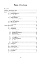
Table of Contents Box Contents...4 GA-6UASL1 Motherboard Layout 5 Chapter 1 Hardware Installation 7 1-1 Installation Precautions 7 1-2 Product Specifications 8 1-3-2 Installing the CPU Cooler 11 1-4 Installing the Memory 12 1-4-1 Dual Channel Memory Configuration 12 1-4-2 Installing a Memory - Gigabyte GA-6UASL3 | Manual - Page 4
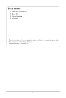
Box Contents GA-6UASL1 motherboard Driver CD Two SATA cables I/O Shield • The box contents above are for reference only and the actual items shall depend on the product package you obtain. The box contents are subject to change without notice. • The motherboard image is for reference only. - 4 - - Gigabyte GA-6UASL3 | Manual - Page 5
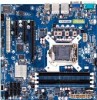
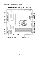
GA-6UASL1 Motherboard Layout - 5 - - Gigabyte GA-6UASL3 | Manual - Page 6
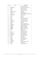
Item Code 1 PCI 2 CASE_OPEN1 3 PCIE3 4 PCIE2 5 PCIE1 6 AUDIO1 (Optional) 7 R_USB1 8 USB_LANA1 9 USB_LANB1 10 VGA1 11 COM1 12 FAN4 13 CPU1 14 VBoot_SEL 15 P2_CPU1 16 NMI_BTN1 17 FAN1 18 PWR_DET1 19 DIMM1B 20 DIMM1A 21 DIMM2B 22 DIMM2A 23 BAT1 24 P1 25 ME_F_JP1 27 BIOS_JP1 - Gigabyte GA-6UASL3 | Manual - Page 7
, carefully read the user's manual and follow these procedures: • Prior to installation, do not remove or break motherboard S/N (Serial Number) sticker or you are uncertain about any installation steps or have a problem related to the use of the product, please consult a certified computer technician. - Gigabyte GA-6UASL3 | Manual - Page 8
Storage Interface ŠŠ 6 x SATA 3Gb/s connectors ŠŠ Support for Intel IRST SATA RAID 0, RAID 1, RAID 5, RAID 10 USB ŠŠ Up to 10 USB 2.0/1.1 ports (6 on the back panel, 3 via the USB brackets connected to the internal USB headers/GA-6UASL1) ŠŠ 1 x Type A USB connector Hardware Installation - Gigabyte GA-6UASL3 | Manual - Page 9
port header ŠŠ 6 x USB 2.0/1.1 ports (GA-6UASL1/2) ŠŠ 1 x RJ-45 port (GA-6UASL1) ŠŠ 2 x RJ-45 port (GA-6UASL2) ŠŠ 1 x COM port ŠŠ 1x the CPU/system fan speed control function is supported will depend on the CPU/system cooler you 9.6 inch x 9.6 inch * GIGABYTE reserves the right to make any changes - Gigabyte GA-6UASL3 | Manual - Page 10
B. Follow the steps below to correctly install the CPU into the motherboard CPU socket. Before installing the CPU, make sure to turn off the computer and unplug the power cord from the power outlet power plug to - Gigabyte GA-6UASL3 | Manual - Page 11
that the Male and Female push pins are joined closely. (Refer to your CPU cooler installation manual for instructions on installing the cooler.) Step 5: After the installation, check the back of the motherboard. If the push pin is inserted as the picture above shows, the installation is complete - Gigabyte GA-6UASL3 | Manual - Page 12
before you begin to install the memory: • Make sure that the motherboard supports the memory. It is recommended that memory of the same capacity, brand, speed, and chips be used. (Go to GIGABYTE's website for the latest supported memory speeds and memory modules.) • Always turn off the computer and - Gigabyte GA-6UASL3 | Manual - Page 13
computer and unplug the power cord from the power outlet to prevent damage to the memory module. Be sure to install DDR3 DIMMs on this motherboard. Installation Step: Step 1. Insert the DIMM memory module vertically into the DIMM slot, and push it down. Step 2. Close the plastic clip at both edges - Gigabyte GA-6UASL3 | Manual - Page 14
Back Panel Connectors GA-6UASL1 GA-6UASL2 GA-6UASL3 Serial Port Connects to serial-based mouse or data processing devices. Video Port The video in port allows connect to video in, which can also apply to video loop thru function. USB 2.0/1.1 Port The USB port supports the USB 2.0/1.1 specification - Gigabyte GA-6UASL3 | Manual - Page 15
is occurring • When removing the cable connected to a back panel connector, first remove the cable from your device and then remove it from the motherboard. • When removing the cable, pull it straight out from the connector. Do not rock it side to side to prevent an electrical short inside - Gigabyte GA-6UASL3 | Manual - Page 16
devices. • After installing the device and before turning on the computer, make sure the device cable has been securely attached to the connector on the motherboard. - 16 - Hardware Installation - Gigabyte GA-6UASL3 | Manual - Page 17
2x12 Main Power Connector) With the use of the power connector, the power supply can supply enough stable power to all the components on the motherboard. Before connecting the power connector, first make sure the power supply is turned off and all devices are properly installed. The power connector - Gigabyte GA-6UASL3 | Manual - Page 18
CLR_CMOS BIOS_WP 3) CASE_OPEN1 (Case Open Intrusion) CLR_CMOS BIOS_WP CI CLR_PWD DPVRM SUR_CEN 1 Pin No. Definition 1 Case Open 2 2 GND MODEM F1_1394 SPDIF_IO 4) PWR_DET1 (Power management connector) 1 GAME 5 Pin No. 1 2 3 6 7 Definition SMB CLK SMB DATA SMB Alert GND 3.3V Sense - Gigabyte GA-6UASL3 | Manual - Page 19
design. When connecting a fan cable, be sure to connect it in the correct orientation (the black connector wire is the ground wire). The motherboard supports CPU fan speed control, which requires the use of a CPU fan with fan speed control design. For optimum heat dissipation, it is recommended - Gigabyte GA-6UASL3 | Manual - Page 20
standard and are compatible with SATA 1.5Gb/s standard. Each SATA connector supports a single SATA device. SATA4 SATA2 SATA0 1 G.QBOFM Pin No. OC When the system is in S4/S5 mode, only the USB ports routed to the F_USB1 header can support the ON/OFF Charge function. Hardware Installation - 20 - - Gigabyte GA-6UASL3 | Manual - Page 21
) The headers conform to USB 2.0/1.1 specification. Pin No. 1 2 3 4 5 Definition Power (5V) USB DYUSB DY+ GND OC When the system is in S4/S5 mode, only the USB ports routed to the F_USB1 header can support the ON/OFF Charge function. 11) USB_A1 (Type A USB Headers) - 21 - Hardware Installation - Gigabyte GA-6UASL3 | Manual - Page 22
12) SGPIO1 (SGPIO HeadFe_PrA)NEL SGPIO is stands for Serial General Purpose Input/Output which is a 4-signal (or 4-wire) bus used between a Host Bus Adapter (HBA) and a backplane. Out of the 4 signals, 3 are drivIRe/CnIRby the HBA and 1 is driven by the backplane. Typically, the HBA is a storage - Gigabyte GA-6UASL3 | Manual - Page 23
14) F_PANEL2 (Front Panel Header) Connect the power switch, reset switch, speaker, chassis intrusion switch/sensor and system status indicator on the chassis to this header according to the pin assignments below. Note the positive and negative pins before connecting the cables. 12 17 18 Pin No. 1 2 - Gigabyte GA-6UASL3 | Manual - Page 24
15) TPM1 (TPM Module Header) Trusted Platform Module(TPM) Platform provides function forsecure generation of cryptographic keys, the ability to limit the use of cryptographic keys, aswell as a hardware pseudo-random number generator. To enable TPM function, you must connect a TPM module and configre - Gigabyte GA-6UASL3 | Manual - Page 25
1-7 Jumper Setting 1) VBoot_SEL 2) BIOS_JP1 3) ME_F_JP1 4) PWD_JP1 5) CLR_CMOS1 - 25 - Hardware Installation - Gigabyte GA-6UASL3 | Manual - Page 26
1) VBoot_SEL (Core Voltage Test Jumper) 1 1-2 Close: Factory test. 1 2-3 Close: Intel default. (Default setting) 2) BIOS_JP1 (BIOS Recovery Jumper) 1 1-2 Close: Normal operation. (Default setting) 1 2-3 Close: BIOS recovery mode. - 26 - Hardware Installation - Gigabyte GA-6UASL3 | Manual - Page 27
3) MFG_F_JP1 (ME Recovery Jumper) 1 1-2 Close: Enable ME recovery. (Default setting) 1 2-3 Close: Disable ME recovery. 4) PWD_JP1 (Clear Password Jumper) Use this jumper to clear the supervisor password. 1 1-2 Close: Normal operation (Default setting) 1 2-3 Close: Clear password. - 27 - - Gigabyte GA-6UASL3 | Manual - Page 28
the jumper cap from the jumper. Failure to do so may cause damage to the motherboard. • After system restart, go to BIOS Setup to load factory defaults (select Load Optimized Defaults) or manually configure the BIOS settings (refer to Chapter 2, "BIOS Setup," for BIOS configurations). Hardware - Gigabyte GA-6UASL3 | Manual - Page 29
. When the power is turned off, the battery on the motherboard supplies the necessary power to the CMOS to keep the configuration BIOS Setup program. • BIOS flashing is potentially risky, if you do not encounter problems of using the current BIOS version, it is recommended that you don't flash - Gigabyte GA-6UASL3 | Manual - Page 30
The Functions of the and keys (For the Main Menu Only) F11: Save CMOS to BIOS This function allows you to save the current BIOS settings to a profile. You can create up to 8 profiles (Profile 1-8) and name each profile. First enter the profile name (to erase the default profile name, - Gigabyte GA-6UASL3 | Manual - Page 31
2-1 The Main Menu Once you enter the BIOS Setup program, the Main Menu (as shown below) appears on the screen. Use arrow keys to move among the items and press to accept or enter other sub-menu. Main Menu Help The on-screen description of a highlighted setup option is displayed on the bottom - Gigabyte GA-6UASL3 | Manual - Page 32
BIOS Version Display version number of the BIOS setup utility. BIOS Build Date Displays the date when the BIOS setup utility was created. Processor Information: CPU Type / CPU Core Frequency / CPU Count Displays the technical specifications for the installed processor. Memory Determines how much - Gigabyte GA-6UASL3 | Manual - Page 33
2-2 Advanced Menu The Advanced menu display submenu options for configuring the function of various hardware components. Select a submenu item, then press Enter to access the related submenu screen. - 33 - BIOS Setup - Gigabyte GA-6UASL3 | Manual - Page 34
2-2-1 Processor Configuration BIOS Setup - 34 - - Gigabyte GA-6UASL3 | Manual - Page 35
independent partitions. Options available: Enabled/Disabled. Default setting is Disabled. Intel AES-NI Support (Intel Advanced Encryption Standard Instructions) Intel Advanced Encryption Standard Instructions (AES-NI), is a symmetric block cipher that encrypts/ decrypts data through several rounds - Gigabyte GA-6UASL3 | Manual - Page 36
1 million cycles per second. The faster the clock, the more instructions the CPU can execute per second. EMT64 Displays Processor EMT64 support status (Note) This item is present only if you install a CPU that supports this feature. For more information about Intel CPUs' unique features, please - Gigabyte GA-6UASL3 | Manual - Page 37
Core Count Displays Processor core count information. CPU Stepping Display processor stepping information. Microcode Revision Display Microcode Revision. Intel HT Technology Display Intel Hyper Threading Technology function support information. BIOS Setup - 37 - - Gigabyte GA-6UASL3 | Manual - Page 38
2-2-2 Memory Configuration Available Memory Total size of system memory detected during POST. Memory Type Display information of installed memory type. Memory Reset Select whether to delete the historical memory data log. System memory will be retested on the next boot-up. Options available: Yes/No. - Gigabyte GA-6UASL3 | Manual - Page 39
2-2-3 Advanced Chipset Configuration Intel VD-d Technology Enable/Disable Intel VD-d Technology function. Options available: Enabled/Disabled. Default setting is Disabled. Intel TXT Technology Enable/Disable Intel TXT Technology function. Options available: Enabled/Disabled. Default setting is - Gigabyte GA-6UASL3 | Manual - Page 40
2-2-4 ACPI Configuration HPET Support (High Precision Event Timer) Enable/Disable HPET Support. Options available: Enabled/Disabled. Default setting is Enabled. WHEA Support (Windows Hardware Error Architecture) Enable/Disable WHEA Support. Options available: Enabled/Disabled. Default setting is - Gigabyte GA-6UASL3 | Manual - Page 41
2-2-5 SATA Controller Configuration SATA Controller When enabled, the SATA controller will function normally. Options available: Enabled/Disabled. Default setting is Enabled. SATA Mode Select the on chip SATA type. IDE Mode: When set to IDE, the SATA controller disables its RAID and AHCI functions - Gigabyte GA-6UASL3 | Manual - Page 42
2-2-6 PCI Configuration PERR# Generation When this item is set to enabled, PCI bus system error (SERR) is generated and is routed to NMI. Options available: Enabled/Disabled. Default setting is Enabled. SERR# Generation When this item is set to enabled, PCI bus parity error (PERR) is generated and - Gigabyte GA-6UASL3 | Manual - Page 43
Onboard Graphics Controller When enabled, the graphic controller will function normally. Options available: enabled/Disabled. Default setting is Enabled. Primary Graphics Select the primary video device that that the BIOS will use for output. Options available: Add-On/Onboard. Default setting is Add - Gigabyte GA-6UASL3 | Manual - Page 44
When enabled, the USB controller will function normally. Options available: Enabled/Disabled. Default setting is Enabled. Legacy USB Support Enables or disables support for legacy USB devices. Options available: Enabled/Disabled. Default setting is Enabled. Port 60/64 Emulation Enable I/O port - Gigabyte GA-6UASL3 | Manual - Page 45
2-2-8 Legacy Device Configuration Serial Port 1/2 When enabled allows you to configure the serial port settings. When set to Disabled, displays no configuration for the serial port. Options available: Enabled/Disabled. Default setting is Enabled. Device Settings Displays Serial Port 1/2 device - Gigabyte GA-6UASL3 | Manual - Page 46
2-2-9 Power Configuration Deep Power Off Mode Enable or Disable Deep Power Off Mode. Options available: Enabled/Disabled. Default setting is Enabled. Power On by RTC Alarm Select whether to wake up the system when an RTC alarm is detected. Options available: Enabled/Disabled. Default setting is - Gigabyte GA-6UASL3 | Manual - Page 47
2-2-10 Console Redirection Console Redirection (Note) Select whether to enable console redirection. Console redirection enables users to manage the system from a remote location. Options available: Serial Port1/Serial Port2/Disabled. Default setting is Disabled. Terminal Type Select a terminal type - Gigabyte GA-6UASL3 | Manual - Page 48
. Resolution 100x31 Enables or disables extended terminal resolution. Options available: Enabled/Disabled. Legacy OS Redirection Resolution On Legacy OS, the number of Rows and Columns supported redirection. Options available: 80x24/80X25. BIOS Setup - 48 - - Gigabyte GA-6UASL3 | Manual - Page 49
2-2-11 Hardware Monitor Press Enter to view the Hardware Monitor screen which displays a real-time record of the CPU/system temperature, fan speed, and voltage. Items on this window are non-configurable. Current CPU/Slot/FP Temperature Displays current bus CPU/Slot/FP temperature. Current FAN 1/2/3 - Gigabyte GA-6UASL3 | Manual - Page 50
: Enabled/Disabled. Default setting is Disabled. Power/Reset Button Lockout Enable or disable Power Button Lockout. Options available: Enabled/Disabled. Default setting is Disabled. TPM Support Select Enabled to activate TPM support feature. - 50 - BIOS Setup - Gigabyte GA-6UASL3 | Manual - Page 51
Enabled. TPM State Select Enabled to activate TPM State function. Options available: Enabled/Disabled. Default setting is Enabled. Pending TPM Support Schedule TPM operation. Options available: None/Enable Take Ownership. Current TPM Status Information Display current TPM status information. Setting - Gigabyte GA-6UASL3 | Manual - Page 52
2-4 Server Management Menu System Information Displays basic system ID information, as well as BIOS version. Press Enter to access the related submenu. Event Log Configuration Displays Event Log advanced settings. Press Enter to access the related submenu. - 52 - BIOS Setup - Gigabyte GA-6UASL3 | Manual - Page 53
2-4-1 System Information The System Management submenu is a simple display page for basic system ID information, as well as System product information. Items on this window are non-configurable. - 53 - BIOS Setup - Gigabyte GA-6UASL3 | Manual - Page 54
2-4-2 Event Log Configuration - 54 - BIOS Setup - Gigabyte GA-6UASL3 | Manual - Page 55
Change SMBIOS Event Settings Press Enter to access the related submenu. View Smbios Event Log Displays Smbios Event Log . Press Enter to View Smbios Event Log. Erase Event Log Choose options for erasing Smbios Event Log Erasing is done prior to any logging activation during reset. Options available: - Gigabyte GA-6UASL3 | Manual - Page 56
2-5 Boot Option Menu The Boot menu allows you to set the drive priority during system boot-up. BIOS setup will display an error message if the drive(s) specified is not bootable. By default, the server searches for boot devices in the following order: 1. Hard drive. 2. UEFI device. 3. Optical disc - Gigabyte GA-6UASL3 | Manual - Page 57
POST Error Pause Select whether to pause POST when a boot-up error is detected. Options available: Enabled/Disabled. Default setting is Enabled. Option ROM Messages Set display mode for Option ROM. Options available: Force BIOS/Keep Current . Default setting is Force BIOS. BIOS Watch Timer Enable/ - Gigabyte GA-6UASL3 | Manual - Page 58
2-6 Boot Manager The Boot manager menu allows you to specify the boot-up drive. BIOS setup will display an error message if the drive(s) specified is not bootable. Built-in EFI Shell Press Enter to configure the device as the boot-up drive. P3: WDC WD1001FAES-22W7A0 Press Enter to configure the - Gigabyte GA-6UASL3 | Manual - Page 59
2-7 Exit Menu The Exit menu displays the various options to quit from the BIOS setup. Highlight any of the exit options then press Enter. Save Changes and Exit Saves changes made and close the BIOS setup. Options available: Yes/No. Discard Changes and Exit Discards changes made and close the BIOS
-
 1
1 -
 2
2 -
 3
3 -
 4
4 -
 5
5 -
 6
6 -
 7
7 -
8
-
9
-
10
-
11
-
12
-
13
-
14
-
15
-
16
-
17
-
18
-
19
-
20
-
21
-
22
-
23
-
24
-
25
-
26
-
27
-
28
-
29
-
30
-
31
-
32
-
33
-
34
-
35
-
36
-
37
-
38
-
39
-
40
-
41
-
42
-
43
-
44
-
45
-
46
-
47
-
48
-
49
-
50
-
51
-
52
-
53
-
54
-
55
-
56
-
57
-
58
-
59
 |
 |

GA-6UASL series
LGA1155 socket motherboard for Intel
®
Core
™
i3 processors/
Intel
®
E3
®
series processors
User's Manual
Rev. 1001