Gigabyte GA-73PVM-S2 Manual
Gigabyte GA-73PVM-S2 Manual
 |
View all Gigabyte GA-73PVM-S2 manuals
Add to My Manuals
Save this manual to your list of manuals |
Gigabyte GA-73PVM-S2 manual content summary:
- Gigabyte GA-73PVM-S2 | Manual - Page 1
GA-73PVM-S2 LGA775 socket motherboard for Intel® CoreTM processor family/ Intel® Pentium® processor family/Intel® Celeron® processor family User's Manual Rev. 1003 12ME-73PVMS2-1003R - Gigabyte GA-73PVM-S2 | Manual - Page 2
Motherboard GA-73PVM-S2 Dec. 6, 2007 Motherboard GA-73PVM-S2 Dec. 6, 2007 - Gigabyte GA-73PVM-S2 | Manual - Page 3
documentations: For detailed product information, carefully read the User's Manual. For instructions on how to use GIGABYTE's unique features, read or download the information on/from the Support&Downloads\Motherboard\Technology Guide page on our website. For product-related information, check - Gigabyte GA-73PVM-S2 | Manual - Page 4
Box Contents ...6 OptionalItems ...6 GA-73PVM-S2 Motherboard Layout 7 Block Diagram ...8 Chapter 1 Hardware Installation 9 1-1 Installation Precautions 9 1-2 Product Specifications 10 1-3 Installing the CPU and CPU Cooler 13 1-3-1 Installing the CPU 13 1-3-2 Installing the CPU Cooler 15 - Gigabyte GA-73PVM-S2 | Manual - Page 5
Utility 64 4-2-2 Updating the BIOS with the @BIOS Utility 67 4-3 EasyTune 5 ...69 4-4 Windows Vista ReadyBoost 70 Chapter 5 Appendix ...71 5-1 Configuring SATA Hard Drive(s 71 5-1-1 Configuring the Onboard SATA Controller 71 5-1-2 Making a SATA RAID/AHCI Driver Diskette 76 5-1-3 Installing - Gigabyte GA-73PVM-S2 | Manual - Page 6
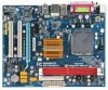
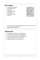
Box Contents GA-73PVM-S2 motherboard Motherboard driver disk User's Manual Quick Installation Guide One IDE cable Two SATA change without notice. • The motherboard image is for reference only. Optional Items Floppy disk drive cable (Part No. 12CF1-1FD001-7*R) 2-port USB 2.0 bracket (Part No. 12CR1 - Gigabyte GA-73PVM-S2 | Manual - Page 7
GA-73PVM-S2 Motherboard Layout KB_MS ATX_12V LGA775 CPU_FAN DDRII1 DDRII2 DVI LPT LAN VGA USB R_USB RTL8211B AUDIO F_AUDIO BIOS CLR_CMOS PCIE_1 nVIDIA® GeForce 7100/ nForce 630i PCIE_16 IT8718 PCI1 SPDIF_O CODEC PCI2 CD_IN COMA F_USB1 F_USB2 FDD ATX IDE GA-73PVM-S2 SATAII0 - Gigabyte GA-73PVM-S2 | Manual - Page 8
) x1 PCI Express Bus PCI Bus ATA-133/100/66/33 IDE Channel 4 SATA 3Gb/s nVIDIA® GeForce 7100/ nForce 630i 10 USB Ports RTL 8211B LAN RJ45 CODEC LPC BUS IT8718 BIOS Floppy LPT Port COM Port PS/2 KB/Mouse MIC(Center/Subwoofer Speaker Out) Line-Out(Front Speaker Out) Line-In(Rear - Gigabyte GA-73PVM-S2 | Manual - Page 9
manual and follow these procedures: • Prior to installation, do not remove or break motherboard S/N (ESD) wrist strap when handling electronic components such as a motherboard, CPU or memory. If you do not have an ESD wrist steps or have a problem related to the use of the product, please consult - Gigabyte GA-73PVM-S2 | Manual - Page 10
Š iTE IT8718 chip: - 1 x floppy disk drive connector supporting up to 1 floppy disk drive Š Integrated in the nVIDIA® GeForce 7100/nForce 630i chipset Š Up to 10 USB 2.0/1.1 ports (6 on the back panel, 4 via the USB brackets connected to the internal USB headers) GA-73PVM-S2 Motherboard - 10 - - Gigabyte GA-73PVM-S2 | Manual - Page 11
1 x D-Sub port Š 6 x USB 2.0/1.1 ports Š 1 x RJ-45 CPU/System temperature detection Š CPU/System fan speed detection Š CPU overheating warning Š CPU/System fan fail warning Š CPU fan speed control (Note 1) BIOS Š 1 x 4 Mbit flash Š Use of licensed AWARD BIOS Š PnP 1.0a, DMI 2.0, SM BIOS - Gigabyte GA-73PVM-S2 | Manual - Page 12
) Š Support for Microsoft® Windows® Vista/XP Š Micro ATX Form Factor; 24.4cm x 19.4cm (Note 1) Whether the CPU fan speed control function is supported will depend on the CPU cooler you install. (Note 2) Available functions in Easytune may differ by motherboard model. GA-73PVM-S2 Motherboard - 12 - Gigabyte GA-73PVM-S2 | Manual - Page 13
before you begin to install the CPU: • Make sure that the motherboard supports the CPU. (Go to GIGABYTE's website for the latest CPU support list.) • Always turn off the computer and unplug the power cord from the power outlet before installing the CPU to prevent hardware damage. • Locate the - Gigabyte GA-73PVM-S2 | Manual - Page 14
pin one corner of the CPU socket (or you may align the CPU notches with the socket alignment keys) and gently insert the CPU into position. Step 5: Once the CPU is properly inserted, replace the load plate and push the CPU socket lever back into its locked position. GA-73PVM-S2 Motherboard - 14 - - Gigabyte GA-73PVM-S2 | Manual - Page 15
. Check that the Male and Female push pins are joined closely. (Refer to your CPU cooler installation manual for instructions on installing the cooler.) Step 5: After the installation, check the back of the motherboard. If the push pin is inserted as the picture above, the installation is complete - Gigabyte GA-73PVM-S2 | Manual - Page 16
Make sure that the motherboard supports the memory. It is recommended that memory of the same capacity, brand, speed, and chips be used. (Go to GIGABYTE's website for the latest memory support list.) • Always into place when the memory module is securely inserted. GA-73PVM-S2 Motherboard - 16 - - Gigabyte GA-73PVM-S2 | Manual - Page 17
an expansion card: • Make sure the motherboard supports the expansion card. Carefully read the manual that came with your expansion card. • Always If necessary, go to BIOS Setup to make any required BIOS changes for your expansion card(s). 7. Install the driver provided with the expansion card - Gigabyte GA-73PVM-S2 | Manual - Page 18
this port. This motherboard provides two ports for video output, DVI-D and D-Sub, and supports dual view function. USB Port The USB port supports the USB 2.0/1.1 specification. Use this port for USB devices such as an USB keyboard/mouse, USB printer, USB flash drive and etc. RJ-45 LAN Port The - Gigabyte GA-73PVM-S2 | Manual - Page 19
speakers in a 4/5.1-channel audio configuration. Mic In Jack (Pink) The default Mic in jack. Microphones must be connected to this jack. Refer to the instructions on setting up a 2/4/5.1-channel audio configuration in Chapter 5, "Configuring 2/4/5.1-Channel Audio." - 19 - Hardware Installation - Gigabyte GA-73PVM-S2 | Manual - Page 20
devices. • After installing the device and before turning on the computer, make sure the device cable has been securely attached to the connector on the motherboard. GA-73PVM-S2 Motherboard - 20 - - Gigabyte GA-73PVM-S2 | Manual - Page 21
supply can supply enough stable power to all the components on the motherboard. Before connecting the power connector, first make sure the power supply the correct orientation. The 12V power connector mainly supplies power to the CPU. If the 12V power connector is not connected, the computer will - Gigabyte GA-73PVM-S2 | Manual - Page 22
drives supported are: 360 KB, 720 KB, 1.2 MB, 1.44 MB, and 2.88 MB. Before connecting a floppy disk drive, be sure to locate pin 1 of the connector and the floppy disk drive cable. The pin 1 of the cable is typically designated by a stripe of different color. 33 1 34 2 GA-73PVM-S2 Motherboard - Gigabyte GA-73PVM-S2 | Manual - Page 23
supports RAID 0, RAID 1, RAID 5 and RAID 0+1. Refer to Chapter 5, "Configuring SATA Hard Drive(s)," for instructions on configuring a RAID array • A RAID 0+1 configuration requires at least four hard drives and the total number of hard drives must be an even number. For this motherboard, you - Gigabyte GA-73PVM-S2 | Manual - Page 24
S3/S4/S5 Off 9) BAT (BATTERY) The battery provides power to keep the values (such as BIOS configurations, date, and time information) in the CMOS when the computer is turned off. Replace the must be handled in accordance with local environmental regulations. GA-73PVM-S2 Motherboard - 24 - - Gigabyte GA-73PVM-S2 | Manual - Page 25
a beep code. One single short beep will be heard if no problem is detected at system startup. If a problem is detected, the BIOS may issue beeps in different patterns to indicate the problem. Refer to Chapter 5, "Troubleshooting," for information about beep codes. • HD (IDE Hard Drive Activity LED - Gigabyte GA-73PVM-S2 | Manual - Page 26
10 NC • The front panel audio header supports HD audio by default. If your chassis provides an AC'97 front panel audio module, refer to the instructions on how to activate AC'97 functioninality via header. 1 Pin No. Definition 1 CD-L 2 GND 3 GND 4 CD-R GA-73PVM-S2 Motherboard - 26 - - Gigabyte GA-73PVM-S2 | Manual - Page 27
out cable, this header can connect to an audio device that supports digital audio in. For purchasing the optional S/PDIF out cable, USB Headers) The headers conform to USB 2.0/1.1 specification. Each USB header can provide two USB ports via an optional USB bracket. For purchasing the optional USB - Gigabyte GA-73PVM-S2 | Manual - Page 28
the jumper. Failure to do so may cause damage to the motherboard. • After system restart, go to BIOS Setup to load factory defaults (select Load Optimized Defaults) or manually configure the BIOS settings (refer to Chapter 2, "BIOS Setup," for BIOS configurations). GA-73PVM-S2 Motherboard - 28 - - Gigabyte GA-73PVM-S2 | Manual - Page 29
17) CI (Chassis Intrusion Header) This motherboard provides a chassis detection feature that detects if the chassis cover has been removed. This function requires a chassis with chassis intrusion detection design. Pin No. Definition 1 Signal 1 2 GND - 29 - Hardware Installation - Gigabyte GA-73PVM-S2 | Manual - Page 30
GA-73PVM-S2 Motherboard - 30 - - Gigabyte GA-73PVM-S2 | Manual - Page 31
that searches and downloads the latest version of BIOS from the Internet and updates the BIOS. For instructions on using the Q-Flash and @BIOS utilities, refer to Chapter 4, "BIOS Update Utilities." • Because BIOS flashing is potentially risky, if you do not encounter problems using the current - Gigabyte GA-73PVM-S2 | Manual - Page 32
Screen The following screen may appear when the computer boots. Motherboard Model BIOS Version Award Modular BIOS v6.00PG, An Energy Star Ally Copyright (C) 1984-2007, Award Software, Inc. GA-73PVM-S2 F1a . . . . : BIOS Setup/Q-Flash : XpressRecovery2 : Boot Menu : Qflash 11 - Gigabyte GA-73PVM-S2 | Manual - Page 33
User Password Save & Exit Setup Exit Without Saving Esc: Quit F8: Q-Flash KLJI: Select Item F10: Save & Exit Setup Time, Date, Hard Disk Type... BIOS Setup Program Function Keys Move the selection bar to select an item Execute command or enter the submenu Main Menu: Exit the - Gigabyte GA-73PVM-S2 | Manual - Page 34
CMOS and exit BIOS Setup. (Pressing can also carry out this task.) „ Exit Without Saving Abandon all changes and the previous settings remain in effect. Pressing to the confirmation message will exit BIOS Setup. (Pressing can also carry out this task.) GA-73PVM-S2 Motherboard - 34 - Gigabyte GA-73PVM-S2 | Manual - Page 35
3 Mode Support [1.44M BIOS automatically detect IDE/SATA devices during the POST. (Default) If no IDE/SATA devices are used, set this item to None so the system will • Manual skip the detection of the device during the POST for faster system startup. Allows you to manually enter the specifications - Gigabyte GA-73PVM-S2 | Manual - Page 36
specifications. If you wish to enter the parameters manually Floppy 3 Mode Support Allows you to BIOS POST. Base Memory Also called conventional memory. Typically, 640 KB will be reserved for the MS-DOS operating system. Extended Memory The amount of extended memory. GA-73PVM-S2 Motherboard - Gigabyte GA-73PVM-S2 | Manual - Page 37
-FDD, USB-ZIP, USB-CDROM, USB-HDD, Legacy LAN, Disabled. Password Check Specifies whether a password is required every time the system boots, or only when you enter BIOS Setup. After configuring this item, set the password(s) under the Set Supervisor/User Password item in the BIOS Main Menu. Setup - Gigabyte GA-73PVM-S2 | Manual - Page 38
installed. If you wish to set up a dual view configuration, set this item to Always Enable. (Note) This item is present only if you install a CPU that supports this feature. For more information about Intel CPUs' unique features, please visit Intel's website. GA-73PVM-S2 Motherboard - 38 - - Gigabyte GA-73PVM-S2 | Manual - Page 39
the first display. (Default) Onboard VGA Sets the onboard VGA as the first display. PEG Sets PCI Express graphics card as the first display. - 39 - BIOS Setup - Gigabyte GA-73PVM-S2 | Manual - Page 40
Mode Enables or disables RAID for the SATA controller integrated in the nVIDIA® GeForce 7100/nForce 630i chipset or configures the SATA controller to AHCI mode. IDE Disables RAID for the SATA controller and configures the SATA controller to PATA mode. (Default) GA-73PVM-S2 Motherboard - 40 - - Gigabyte GA-73PVM-S2 | Manual - Page 41
Interface (AHCI) is an interface specification that allows the storage driver to enable advanced Serial ATA features such as Native Command Queuing and hot plug. RAID Enables RAID for the SATA controller. SATA-II Pri-Master RAID Enables or disables RAID for the first SATA 3Gb/s connector - Gigabyte GA-73PVM-S2 | Manual - Page 42
normal speed of 10/100/1000 Mbps in Windows mode or when the LAN Boot ROM is activated. When a Cable Problem Occurs... If a cable problem occurs on a specified pair of wires, the Status field will show length shown is the approximate length of the attached LAN cable. GA-73PVM-S2 Motherboard - 42 - - Gigabyte GA-73PVM-S2 | Manual - Page 43
storage detect Determines whether to detect USB storage devices, including USB flash drives and USB hard drives during the POST. (Default: Enabled) Onboard Serial Port 1 Enables or disables the first serial Port Mode is set to ECP or ECP+EPP mode. Options are: 3 (default), 1. - 43 - BIOS Setup - Gigabyte GA-73PVM-S2 | Manual - Page 44
Wake Up Modem Ring On USB Resume from Suspend Power-On by Alarm x Day of Month Alarm x Time (hh:mm:ss) Alarm HPET Support (Note) Power On By from a modem that supports wake-up function. (Default: Enabled) (Note) Supported on Windows® Vista® operating system only. GA-73PVM-S2 Motherboard - 44 - - Gigabyte GA-73PVM-S2 | Manual - Page 45
USB device. (Default: Disabled ) Power-On by Alarm Determines whether to power on the system at a desired time. (Default: Disabled) If enabled, set the date and time as following: Day of Month Alarm : Turn on the system at a specific (Note) Supported on Windows® Vista® operating system only. - 45 - Gigabyte GA-73PVM-S2 | Manual - Page 46
Help F7: Optimized Defaults BIOS auto-assigns IRQ to the first PCI slot. (Default) Assigns IRQ 3,4,5,7,9,10,11,12,14,15 to the first PCI slot. BIOS auto-assigns IRQ to the second PCI slot. (Default) Assigns IRQ 3,4,5,7,9,10,11,12,14,15 to the second PCI slot. GA-73PVM-S2 Motherboard - 46 - - Gigabyte GA-73PVM-S2 | Manual - Page 47
device attached to the motherboard CI header. If CPU Temperature Displays current system/CPU temperature. Current CPU/SYSTEM FAN Speed (RPM) Displays current CPU/system fan speed. CPU Warning Temperature Sets the warning threshold for CPU temperature. When CPU temperature exceeds the threshold, BIOS - Gigabyte GA-73PVM-S2 | Manual - Page 48
is configurable only if CPU Smart FAN Control is set to Enabled. Auto Lets BIOS autodetect the type of CPU fan installed and sets the optimal CPU fan control mode. (Default) Voltage Sets Voltage mode for a 3-pin CPU fan. PWM Sets PWM mode for a 4-pin CPU fan. GA-73PVM-S2 Motherboard - 48 - - Gigabyte GA-73PVM-S2 | Manual - Page 49
Value Displays the following CPU and memory speed. Setting shows the value you manually adjust; Current Value shows the current operating frequency. Current CPU Freq, MHz Displays the CPU speeds. (Note) This item appears only if you install a CPU that supports this feature. - 49 - BIOS Setup - Gigabyte GA-73PVM-S2 | Manual - Page 50
can be increased by 1% ~ 50%. CPU Clock Ratio (Note) Allows you to alter the clock ratio for the installed CPU. The item is present only if a CPU with unlocked clock ratio is installed. (Note) This item appears only if you install a CPU that supports this feature. GA-73PVM-S2 Motherboard - 50 - - Gigabyte GA-73PVM-S2 | Manual - Page 51
the CPU voltage as required. The adjustable range is dependent on the CPU being installed. (Default: Normal) Note: Increasing CPU voltage may result in damage to your CPU or reduce the useful life of the CPU. Normal CPU Vcore Displays the normal operating voltage of your CPU. - 51 - BIOS Setup - Gigabyte GA-73PVM-S2 | Manual - Page 52
Press on this item and then press the key to load the optimal BIOS default settings. The BIOS defaults settings helps the system to operate in optimum state. Always load the Optimized defaults after updating the BIOS or after clearing the CMOS values. GA-73PVM-S2 Motherboard - 52 - - Gigabyte GA-73PVM-S2 | Manual - Page 53
changes. When the Password Check item is set to System, you must enter the supervisor password (or user password) at system startup and when entering BIOS Setup. User Password When the Password Check item is set to System, you must enter the supervisor password (or user password) at system startup - Gigabyte GA-73PVM-S2 | Manual - Page 54
F8: Q-Flash KLJI: Select Item F10: Save & Exit Setup Abandon all Data Press on this item and press the key. This exits the BIOS Setup without saving the changes made in BIOS Setup to the CMOS. Press or to return to the BIOS Setup Main Menu. GA-73PVM-S2 Motherboard - 54 - - Gigabyte GA-73PVM-S2 | Manual - Page 55
appears asking for installation of the RAID controller driver, please insert the motherboard driver disk and select to install the driver automatically in the dialog box. • For USB 2.0 driver support under the Windows XP operating system, please install the Windows XP Service Pack 1 or later. After - Gigabyte GA-73PVM-S2 | Manual - Page 56
all the tools and applications that GIGABYTE develops and some free software. You may press the Install button following an item to install it. 3-3 Driver CD Information This page provides information about the drivers, applications and tools in this driver disk. GA-73PVM-S2 Motherboard - 56 - - Gigabyte GA-73PVM-S2 | Manual - Page 57
3-4 Hardware Information This page provides information about the hardware devices on this motherboard. 3-5 Contact Us Check the contacts information of the GIGABYTE headquarter in Taiwan and the overseas branch offices on the last page of this manual. - 57 - Drivers Installation - Gigabyte GA-73PVM-S2 | Manual - Page 58
GA-73PVM-S2 Motherboard - 58 - - Gigabyte GA-73PVM-S2 | Manual - Page 59
It is recommended to back up your system soon after the operating system and drivers are installed. • The amount of data and hard drive access speed may affect using Xpress Recovery2. • USB hard drives are not supported. • Hard drives in RAID/AHCI mode are not supported. "*" Xpress Recovery2 checks - Gigabyte GA-73PVM-S2 | Manual - Page 60
Drive 1. Set CD-ROM drive as the first boot device under "Advanced BIOS Features" in the BIOS Setup program. Save the changes and exit. 2. When partitioning your hard drive for example, NTFS) and begin the installation of the operating system (Figure 3). Figure 3 GA-73PVM-S2 Motherboard - 60 - - Gigabyte GA-73PVM-S2 | Manual - Page 61
4. After the operating system is installed, right-click the My Computer icon on your desktop and select Manage (Figure 4). Go to Computer Management to check disk allocation. Xpress Recovery2 will save the backup file to the unallocated space (black stripe along the top)(Figure 5). Please note that - Gigabyte GA-73PVM-S2 | Manual - Page 62
from the motherboard driver disk to access Modular BIOS v6.00PG, An Energy Star Ally Copyright (C) 1984-2007, Award Software, Inc. GA-73PVM-S2 F1a . . . . : BIOS Setup/Q- to check disk allocation. Figure 12 GA-73PVM-S2 Motherboard Xpress Recovery2 will automatically create a new partition to - Gigabyte GA-73PVM-S2 | Manual - Page 63
D. Using the Restore Function in Xpress Recovery2 Select RESTORE to restore the backup to your hard drive in case the system breaks down. The RESTORE option will not be present if no backup is created before (Figure 13, 14). Figure 13 Figure 14 E. Removing the Backup 1. If you wish to remove the - Gigabyte GA-73PVM-S2 | Manual - Page 64
, if the BIOS update file is saved to a hard drive in RAID/AHCI mode or a hard drive attached to an independent IDE/SATA controller, use the key during the POST to access Q-Flash. Award Modular BIOS v6.00PG, An Energy Star Ally Copyright (C) 1984-2007, Award Software, Inc. GA-73PVM-S2 F1a - Gigabyte GA-73PVM-S2 | Manual - Page 65
arrow key to select Update BIOS from Drive and press . • The Save Main BIOS to Drive option allows you to save the current BIOS file. • Q-Flash only supports USB flash drive or hard drives using FAT32/16/12 file system. • If the BIOS update file is saved to a hard drive in RAID/AHCI mode or - Gigabyte GA-73PVM-S2 | Manual - Page 66
F8: Q-Flash KLJI: Select Item F10: Save & Exit Setup Load Optimized Defaults Press to load BIOS defaults Step 6: Select Save & Exit Setup and then press to save settings to CMOS and exit BIOS Setup. The procedure is complete after the system restarts. GA-73PVM-S2 Motherboard - 66 - - Gigabyte GA-73PVM-S2 | Manual - Page 67
and Using @BIOS: Use the motherboard driver disk included with the motherboard to install @BIOS. • Installing the @BIOS utility. • Accessing the @BIOS utility. Click Start>All Programs>GIGABYTE>@BIOS Select @BIOS and click Install. C. Options and Instructions: 1. Save the Current BIOS File In - Gigabyte GA-73PVM-S2 | Manual - Page 68
in an unbootable system. • If the BIOS update file for your motherboard is not present on the @BIOS server site, please manually download the BIOS update file from GIGABYTE's website and follow the instructions in "Update the BIOS without Using the Internet Update Function" below. Step 4: As the - Gigabyte GA-73PVM-S2 | Manual - Page 69
the BIOS Setup program. EasyTune 5 provides the following functions : (Note 1) overclocking/overvoltage, C.I.A./ M.I.B. (Note 2), smart fan control, and hardware monitoring and warning. (For instructions on using EasyTune5, read or download the information on/from the Support\Motherboard\Utility - Gigabyte GA-73PVM-S2 | Manual - Page 70
the slider or spin box. Click Apply and then OK to turn on ReadyBoost. • The USB flash drive must have at least 256 MB of space. • The recommended amount of memory to use for ReadyBoost acceleration is one to three times the amount of RAM installed in your computer. GA-73PVM-S2 Motherboard - 70 - - Gigabyte GA-73PVM-S2 | Manual - Page 71
step if you do not want to create RAID array on the SATA controller. (Note 2) Required when the SATA controller is set to AHCI or RAID mode. (Note 3) To install Windows Vista onto your SATA RAID drives, please go to GIGABYTE's website to download the Windows Vista SATA RAID driver. - 71 - Appendix - Gigabyte GA-73PVM-S2 | Manual - Page 72
ESC: Exit F1: General Help F7: Optimized Defaults The BIOS Setup menus described in this section may differ from the exact settings for your motherboard. The actual BIOS Setup menu options you will see shall depend on the motherboard you have and the BIOS version. GA-73PVM-S2 Motherboard - 72 - - Gigabyte GA-73PVM-S2 | Manual - Page 73
RAID mode. The supported RAID modes include Mirrored, Striped, Spanned, Striped Mirror, and RAID5. The following procedure demonstrates how a RAID 0 array is created. Step 4: If RAID 0 (Striped) is selected, you can manually 4 KB to 128 KB RAID Mode: Striped MediaShield BIOS Jul 27 2007 - Define - Gigabyte GA-73PVM-S2 | Manual - Page 74
or to abort. (We recommend that you clear the MBR to reduce drive errors.) RAID Mode: Striped MediaShield BIOS Jul 27 2007 - Define a New Array - Stripe Block: Optimal Free Disks Port Disk Back [F7] Finish [TAB] Navigate [KL] Select [ENTER] Popup Figure 6 GA-73PVM-S2 Motherboard - 74 - - Gigabyte GA-73PVM-S2 | Manual - Page 75
RAID array that you have created (Figure 7). (Note: BBS stands for BIOS Boot Specification. This indicates that the boot device is defined in the BIOS.) Boot BBS MediaShield BIOS RAID mode, stripe block size, hard drive model name, and hard drive capacity, etc. RAID the NVIDIA RAID setup utility, - Gigabyte GA-73PVM-S2 | Manual - Page 76
users without a startup disk: Use an alternative system and insert the motherboard driver disk. From your optical drive folder, double click the MENU.exe file in the BootDrv folder (Figure 3). A command prompt window will open similar to that in Figure 2. GA-73PVM-S2 Motherboard Figure 3 - 76 - - Gigabyte GA-73PVM-S2 | Manual - Page 77
RAID/AHCI driver diskette and configured the required BIOS RAID/AHCI driver and press (Figure 2). Windows Setup Setup could not determine the type of one or more mass storage devices installed in your system, or you have chosen to manually specify an adapter. Currently, Setup will load support - Gigabyte GA-73PVM-S2 | Manual - Page 78
one or some file(s) cannot be found, please check the floppy disk or copy the correct SATA RAID driver again from the motherboard driver disk. (Note) The selectable item(s) displayed in Figure 3 may differ according to the RAID or AHCI driver you will install. GA-73PVM-S2 Motherboard - 78 - - Gigabyte GA-73PVM-S2 | Manual - Page 79
installation will be finished in about one minute. Windows Setup Setup will load support for the following mass storage device(s): NVIDIA RAID Driver (required) NVIDIA nForce Storage Controller (required) * To specify additional SCSI adapters, CD-ROM drives, or special disk controllers for use - Gigabyte GA-73PVM-S2 | Manual - Page 80
.exe file to extract the driver files. Finally, insert the floppy disk and browse to the floppy disk.) Figure 8 (Note) For AHCI drives, installation of Windows Vista does not require you to install the SATA AHCI driver in advance during the OS installation process. GA-73PVM-S2 Motherboard - 80 - - Gigabyte GA-73PVM-S2 | Manual - Page 81
Step 3: When a screen as shown in Figure 9 appears, select NVIDIA nForce RAID Controller and press Next. Figure 9 Step 4: After the driver is loaded, the screen will show the RAID hard drive. Select the RAID hard drive onto which you want to install the operating system and then press Next to - Gigabyte GA-73PVM-S2 | Manual - Page 82
driver, make sure the "Microsoft UAA Bus driver for High Definition Audio" has been installed from the motherboard driver disk and your operating system has been updated with the latest Service : Front speaker out, Rear speaker out, and Center/Subwoofer speaker out. GA-73PVM-S2 Motherboard - 82 - - Gigabyte GA-73PVM-S2 | Manual - Page 83
Step 2: Click the Audio I/O tab. In the speaker list on the left, select 2CH Speaker, 4CH Speaker, or 6CH Speaker according to the type of speaker configuration you wish to set up. Step 3: The pictures to the right show the 2-, 4-, 5.1-channel speaker configurations. 2-Channel Speakers: 4-Channel - Gigabyte GA-73PVM-S2 | Manual - Page 84
the Audio I/O tab. On the Connector Settings box, select the Mute rear panel output when front headphone plugged in check box. Click OK to complete. GA-73PVM-S2 Motherboard - 84 - - Gigabyte GA-73PVM-S2 | Manual - Page 85
external decoder. A. Installing the S/PDIF Out Cable: Step 1: First, attach the connector at the end of the cable to the SPDIF_O header on your motherboard. Pin 1 (the red wire) of the S/PDIF out cable must align with pin 1 of the SPDIF_O header. Incorrect connection may render the device unusable - Gigabyte GA-73PVM-S2 | Manual - Page 86
section. In the S/PDIF Settings dialog box, select an output sampling rate and select (or disable) the output source. Click OK to complete the configuration. GA-73PVM-S2 Motherboard - 86 - - Gigabyte GA-73PVM-S2 | Manual - Page 87
5-2-3 Configuring Microphone Recording Step 1: After installing the audio driver, the Audio Manager icon will appear in your system tray. Doubleclick the icon to access the Audio Control Panel. Step 2: Connect your microphone to the - Gigabyte GA-73PVM-S2 | Manual - Page 88
, or you will not hear any sound when playing back the recording you just made. Select Realtek HD Audio Input in the Mixer device list GA-73PVM-S2 Motherboard Recording Control - 88 - - Gigabyte GA-73PVM-S2 | Manual - Page 89
Step 6: To raise the recording and playing sound for the microphone, go to Options in Master Volume and select Advanced Controls. Click the Advanced button under a volume control option (e.g. Front Green In, Front Pink In). In the Other Controls field, select the 1 Microphone Boost check box. Step - Gigabyte GA-73PVM-S2 | Manual - Page 90
setting error 1 long, 1 short: Memory or motherboard error 1 long, 2 short: Monitor or graphics card error 1 long, 3 short: Keyboard error 1 long, 9 short: BIOS ROM error Continuous long beeps: Graphics card not inserted properly Continuous short beeps: Power error GA-73PVM-S2 Motherboard - 90 - - Gigabyte GA-73PVM-S2 | Manual - Page 91
Procedure If you encounter any troubles during system startup, follow the troubleshooting procedure below to solve the problem. START Turn off the power. Remove all peripherals, connecting cables, and power cord etc. Make sure the motherboard does not short-circuit with the chassis Yes - Gigabyte GA-73PVM-S2 | Manual - Page 92
. END If the procedure above is unable to solve your problem, contact the place of purchase or local dealer for help. Or go to the Support&Downloads\Technical Service Zone page to submit your question. Our customer service staff will reply you as soon as possible. GA-73PVM-S2 Motherboard - 92 - - Gigabyte GA-73PVM-S2 | Manual - Page 93
GIGABYTE. Our Commitment to Preserving the Environment In addition to high-efficiency performance, all GIGABYTE motherboards local government office, your household waste disposal service or where you purchased the product for user's manual and we will be glad to help you with your effort. - - Gigabyte GA-73PVM-S2 | Manual - Page 94
disposed of properly. China Restriction of Hazardous Substances Table The following table is supplied in compliance with China's Restriction of Hazardous Substances (China RoHS) requirements: GA-73PVM-S2 Motherboard - 94 - - Gigabyte GA-73PVM-S2 | Manual - Page 95
- 95 - Appendix - Gigabyte GA-73PVM-S2 | Manual - Page 96
GA-73PVM-S2 Motherboard - 96 - - Gigabyte GA-73PVM-S2 | Manual - Page 97
- 97 - Appendix - Gigabyte GA-73PVM-S2 | Manual - Page 98
GA-73PVM-S2 Motherboard - 98 - - Gigabyte GA-73PVM-S2 | Manual - Page 99
231, Taiwan TEL: +886-2-8912-4888 FAX: +886-2-8912-4003 Tech. and Non-Tech. Support (Sales/Marketing) : http://ggts.gigabyte.com.tw WEB address (English): http://www.gigabyte.com.tw WEB address (Chinese): http://www.gigabyte.tw y G.B.T. INC. - U.S.A. TEL: +1-626-854-9338 FAX: +1-626-854-9339 Tech - Gigabyte GA-73PVM-S2 | Manual - Page 100
language in the language list on the top right corner of the website. y GIGABYTE Global Service System To submit a technical or non-technical (Sales/ Marketing) question, please link to : http://ggts.gigabyte.com.tw Then select your language to enter the system. GA-73PVM-S2 Motherboard - 100 -
-
 1
1 -
 2
2 -
 3
3 -
 4
4 -
 5
5 -
 6
6 -
 7
7 -
8
-
9
-
10
-
11
-
12
-
13
-
14
-
15
-
16
-
17
-
18
-
19
-
20
-
21
-
22
-
23
-
24
-
25
-
26
-
27
-
28
-
29
-
30
-
31
-
32
-
33
-
34
-
35
-
36
-
37
-
38
-
39
-
40
-
41
-
42
-
43
-
44
-
45
-
46
-
47
-
48
-
49
-
50
-
51
-
52
-
53
-
54
-
55
-
56
-
57
-
58
-
59
-
60
-
61
-
62
-
63
-
64
-
65
-
66
-
67
-
68
-
69
-
70
-
71
-
72
-
73
-
74
-
75
-
76
-
77
-
78
-
79
-
80
-
81
-
82
-
83
-
84
-
85
-
86
-
87
-
88
-
89
-
90
-
91
-
92
-
93
-
94
-
95
-
96
-
97
-
98
-
99
-
100
 |
 |

GA-73PVM-S2
LGA775 socket motherboard for Intel
®
Core
TM
processor family/
Intel
®
Pentium
®
processor family/Intel
®
Celeron
®
processor family
User's Manual
Rev. 1003
12ME-73PVMS2-1003R