Gigabyte GA-73PVM-S2H Manual
Gigabyte GA-73PVM-S2H Manual
 |
UPC - 818313004338
View all Gigabyte GA-73PVM-S2H manuals
Add to My Manuals
Save this manual to your list of manuals |
Gigabyte GA-73PVM-S2H manual content summary:
- Gigabyte GA-73PVM-S2H | Manual - Page 1
GA-73PVM-S2H LGA775 socket motherboard for Intel® Core TM processor family/ Intel® Pentium® processor family/Intel® Celeron® processor family User's Manual Rev. 1004 12ME-73PVMS2H-1004R - Gigabyte GA-73PVM-S2H | Manual - Page 2
Motherboard GA-73PVM-S2H Oct. 11, 2007 Motherboard GA-73PVM-S2H Oct. 11, 2007 - Gigabyte GA-73PVM-S2H | Manual - Page 3
of documentations: For detailed product information, carefully read the User's Manual. For instructions on how to use GIGABYTE's unique features, read or download the information on/from the Support\Motherboard\Technology Guide page on our website. For product-related information, check on our - Gigabyte GA-73PVM-S2H | Manual - Page 4
Items...6 GA-73PVM-S2H Motherboard Layout 7 Block Diagram...8 Chapter 1 Hardware Installation 9 1-1 Installation Precautions 9 1-2 Product Specifications 10 1-3 Installing the CPU and CPU Cooler 13 1-3-1 Installing the CPU 13 1-3-2 Installing the CPU Cooler 15 1-4 Installing the Memory 16 - Gigabyte GA-73PVM-S2H | Manual - Page 5
Chipset Drivers 57 3-2 Software Applications 58 3-3 Driver CD Information 58 3-4 Hardware Information 59 3-5 Contact Us ...59 Chapter 4 Unique Features 61 4-1 Xpress Recovery2 61 4-2 BIOS Update Utilities 66 4-2-1 Updating the BIOS with the Q-Flash Utility 66 4-2-2 Updating the BIOS - Gigabyte GA-73PVM-S2H | Manual - Page 6
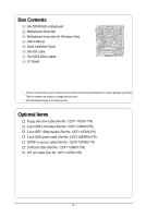
Box Contents GA-73PVM-S2H motherboard Motherboard driver disk Motherboard driver disk (for Windows Vista) User's Manual Quick Installation Guide One IDE cable Two SATA 3Gb/s cables I/O Shield • The box contents above are for reference only and the actual items shall depend on product package - Gigabyte GA-73PVM-S2H | Manual - Page 7
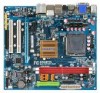
GA-73PVM-S2H Motherboard Layout KB_MS ATX_12V VGA DVI HDMI OPTICAL ESATA USB 1394 LAN USB RTL 8211B AUDIO F_AUDIO CD_IN PCIE_1 PCIE_16 CODEC PCI1 PCI2 SPDIF_IO F_USB3 F_USB1 F_USB2 LGA775 CPU_FAN ATX LPT GA-73PVM-S2H nVIDIA® GeForce 7100/ nForce 630i IDE SATAII1 SATAII0 SATAII2 - Gigabyte GA-73PVM-S2H | Manual - Page 8
) D-Sub Host Interface DDR2 800/667/533 MHz ATA-133/100/66/33 IDE Channel PCI Express x16 1 PCI Express x1 PCIe CLK (100 MHz) x1 PCI Express Bus PCI Bus TSB43AB23 nVIDIA® GeForce 7100/ nForce 630i 4 SATA 3Gb/s 10 USB Ports RTL 8211B LAN RJ45 LPC BUS IT8718 CODEC BIOS Floppy LPT Port COM - Gigabyte GA-73PVM-S2H | Manual - Page 9
's manual and follow these procedures: • Prior to installation, do not remove or break motherboard S/N wrist strap when handling electronic components such as a motherboard, CPU or memory. If you do not have an ESD wrist steps or have a problem related to the use of the product, please consult - Gigabyte GA-73PVM-S2H | Manual - Page 10
processor in the LGA 775 package (Go to GIGABYTE's website for the latest CPU support list.) L2 cache varies with CPU 1333/1066/800 MHz FSB nVIDIA® GeForce 7100/nForce 630i 2 x 1.8V DDR2 DIMM sockets supporting up to 4 GB of system memory Support for DDR2 800/667/533 MHz memory modules (Go - Gigabyte GA-73PVM-S2H | Manual - Page 11
fan header 1 x system fan header 1 x front panel header 1 x front panel audio header 1 x CD In connector 1 x S/PDIF In/Out header 1 x IEEE 1394a header 3 x USB 2.0/1.1 headers 1 x parallel port header 1 x serial port header 1 x chassis intrusion header 1 x power LED - Gigabyte GA-73PVM-S2H | Manual - Page 12
BIOS Norton Internet Security (OEM version) Support for Microsoft® Windows® Vista/XP Micro ATX Form Factor; 24.4cm x 22.0cm (Note 1) The DVI-D port does not support D-Sub connection by adapter. (Note 2) Available functions in Easytune may differ by motherboard model. GA-73PVM-S2H Motherboard - Gigabyte GA-73PVM-S2H | Manual - Page 13
so according to your hardware specifications including the CPU, graphics card, memory, hard drive, etc. 1-3-1 Installing the CPU A. Locate the alignment keys on the motherboard CPU socket and the notches on the CPU. LGA775 CPU Socket Alignment Key LGA 775 CPU Alignment Key Pin One Corner of the - Gigabyte GA-73PVM-S2H | Manual - Page 14
one corner of the CPU socket (or you may align the CPU notches with the socket alignment keys) and gently insert the CPU into position. Step 5: Once the CPU is properly inserted, replace the load plate and push the CPU socket lever back into its locked position. GA-73PVM-S2H Motherboard - 14 - - Gigabyte GA-73PVM-S2H | Manual - Page 15
. Check that the Male and Female push pins are joined closely. (Refer to your CPU cooler installation manual for instructions on installing the cooler.) Step 5: After the installation, check the back of the motherboard. If the push pin is inserted as the picture above, the installation is complete - Gigabyte GA-73PVM-S2H | Manual - Page 16
in the picture on the left, place your fingers on the top edge of the memory, push down on the memory and insert it vertically into the memory socket. Step 2: The clips at both ends of the socket will snap into place when the memory module is securely inserted. GA-73PVM-S2H Motherboard - 16 - - Gigabyte GA-73PVM-S2H | Manual - Page 17
an expansion card: • Make sure the motherboard supports the expansion card. Carefully read the manual that came with your expansion card. • Always If necessary, go to BIOS Setup to make any required BIOS changes for your expansion card(s). 7. Install the driver provided with the expansion card - Gigabyte GA-73PVM-S2H | Manual - Page 18
x16 Graphics Card Support List The items below are supported under Windows XP operating system only. When using an add-on graphics card, please first delete the onboard graphics driver before installing the driver for the add-on graphics card. For more information, please go to GIGABYTE's website - Gigabyte GA-73PVM-S2H | Manual - Page 19
Graphics Chip ATi VIA Maker GIGABYTE GIGABYTE GIGABYTE GIGABYTE GIGABYTE GIGABYTE GIGABYTE GIGABYTE GIGABYTE GIGABYTE GIGABYTE GIGABYTE GIGABYTE GIGABYTE GIGABYTE GIGABYTE GIGABYTE GIGABYTE GIGABYTE GIGABYTE GIGABYTE GIGABYTE GIGABYTE GIGABYTE ATi ASUS ASUS MSI MSI S3 Model Name GV-RX30HM128D GV- - Gigabyte GA-73PVM-S2H | Manual - Page 20
.) In Windows XP, select Start>Control Panel>Sounds and Audio Devices Properties>Audio, set the Default device for sound playback toNVIDIAHDMIAudioWave. In Windows Vista, select Start>Control Panel> Sound, select NVIDIA HDMI Audio Device and then click Set Default. GA-73PVM-S2H Motherboard - 20 - Gigabyte GA-73PVM-S2H | Manual - Page 21
. Before using this feature, ensure that your audio system provides a n optical digital audio in connector. USB Port The USB port supports the USB 2.0/1.1 specification. Use this port for USB devices such as an USB keyboard/mouse, USB printer, USB flash drive and etc. IEEE 1394a Port The IEEE 1394 - Gigabyte GA-73PVM-S2H | Manual - Page 22
• Playback software: CyberLink PowerDVD 7.3 (Note: Hardware Acceleration is not supported) File Format Non-protected contents HD-DVD Blu-ray Suitable Resolution Windows XP Windows Vista 1920 x 1080p 1920 x 1080p 1920 x 1080p 1920 x 1080p 1920 x 1080p 1920 x 1080p GA-73PVM-S2H Motherboard - 22 - - Gigabyte GA-73PVM-S2H | Manual - Page 23
devices. • After installing the device and before turning on the computer, make sure the device cable has been securely attached to the connector on the motherboard. - 23 - Hardware Installation - Gigabyte GA-73PVM-S2H | Manual - Page 24
cable to the power connector in the correct orientation. The 12V power connector mainly supplies power to the CPU. If the 12V power connector is not connected, the computer will not start. • To meet -5V +5V +5V +5V (Only for 2x12-pinATX) GND (Only for 2x12-pinATX) GA-73PVM-S2H Motherboard - 24 - - Gigabyte GA-73PVM-S2H | Manual - Page 25
it in the correct orientation. Most fans are designed with color-coded power connector wires. A red power connector wire indicates a positive connection and requires a +12V voltage. The black connector wire is the ground wire. The motherboard supports CPU fan speed control, which requires the use of - Gigabyte GA-73PVM-S2H | Manual - Page 26
TA 1.5Gb/s standard. Each SATA connector supports a single SA TA device. The GeForce 7100/nForce 630i controller supports RAID 0, RAID 1, RAID 5 and RAID 0+1. Refer to Chapter 5, "Configuring SA TA Hard Drive(s)," for instructions on configuring a RAID array. Pin No. Definition 1 GND SATAII1 - Gigabyte GA-73PVM-S2H | Manual - Page 27
2 MPD- 3 MPD- System Status LED S0 On S1 Blinking S3/S4/S5 Off 9) BATTERY The battery provides power to keep the values (such as BIOS configurations, date, and time information) in the CMOS when the computer is turned off. Replace the battery when the battery voltage drops to a low level - Gigabyte GA-73PVM-S2H | Manual - Page 28
beep code. One single short beep will be heard if no problem is detected at system startup. If a problem is detected, the BIOS may issue beeps in different patterns to indicate the problem. Refer to Chapter 5, "Troubleshooting," for information about beep codes . GA-73PVM-S2H Motherboard - 28 - - Gigabyte GA-73PVM-S2H | Manual - Page 29
• The front panel audio header supports HD audio by default. If your chassis provides an AC'97 front panel audio module, refer to the instructions on how to activate AC'97 functioninality via the audio software in Chapter 5, "Configuring 2/4/5.1/7.1-Channel Audio." • Audio signals will be present - Gigabyte GA-73PVM-S2H | Manual - Page 30
D USB DX+ USB DY+ GND GND No Pin NC • Do not plug the IEEE 1394 bracket (2x5-pin) cable into the USB header. • Prior to installing the USB bracket, be sure to turn off your computer and unplug the power cord from the power outlet to prevent damage to the USB bracket. GA-73PVM-S2H Motherboard - 30 - Gigabyte GA-73PVM-S2H | Manual - Page 31
dealer. Pin No. Definition 2 10 1 TPA+ 2 TPA- 1 9 3 GND 4 GND 5 TPB+ 6 TPB- 7 Power (12V) 8 Power (12V) 9 No Pin 10 GND • Do not plug the USB bracket cable into the IEEE 1394a header. • Prior to installing the IEEE 1394a bracket, be sure to turn off your computer and unplug - Gigabyte GA-73PVM-S2H | Manual - Page 32
SLCT GND 18) CI (Chassis Intrusion Header) This motherboard provides a chassis detection feature that detects if the chassis cover has been removed. This function requires a chassis with chassis intrusion detection design. Pin No. Definition 1 Signal 1 2 GND GA-73PVM-S2H Motherboard - 32 - - Gigabyte GA-73PVM-S2H | Manual - Page 33
the jumper. Failure to do so may cause damage to the motherboard. • After system restart, go to BIOS Setup to load factory defaults (select Load Optimized Defaults) or manually configure the BIOS settings (refer to Chapter 2, "BIOS Setup," for BIOS configurations). - 33 - Hardware Installation - Gigabyte GA-73PVM-S2H | Manual - Page 34
GA-73PVM-S2H Motherboard - 34 - - Gigabyte GA-73PVM-S2H | Manual - Page 35
Windows-based utility that searches and downloads the latest version of BIOS from the Internet and updates the BIOS. For instructions on using the Q-Flash and @BIOS utilities, refer to Chapter 4, "BIOS Update Utilities." • Because BIOS flashing is potentially risky, if you do not encounter problems - Gigabyte GA-73PVM-S2H | Manual - Page 36
following screen may appear when the computer boots. Motherboard Model BIOS Version Award Modular BIOS v6.00PG, An Energy Star Ally Copyright (C) 1984-2007, Award Software, Inc. GA-73PVM-S2H F4a . . . . : BIOS Setup/Q-Flash : XpressRecovery2 : Boot Menu : Qflash 09/28/2007-NF73 - Gigabyte GA-73PVM-S2H | Manual - Page 37
Set User Password Save & Exit Setup Exit Without Saving Esc: Quit F8: Q-Flash Select Item F10: Save & Exit Setup Time, Date, Hard Disk Type... BIOS Setup Program Function Keys Move the selection bar to select an item Execute command or enter the submenu Main Menu: Exit the - Gigabyte GA-73PVM-S2H | Manual - Page 38
CMOS and exit BIOS Setup. (Pressing can also carry out this task.) Exit Without Saving Abandon all changes and the previous settings remain in effect. Pressing to the confirmation message will exit BIOS Setup. (Pressing can also carry out this task.) GA-73PVM-S2H Motherboard - 38 - Gigabyte GA-73PVM-S2H | Manual - Page 39
Floppy 3 Mode Support Halt On [1.44M, 3.5"] [Disabled] [All, But Keyboard] Base Memory Extended Memory 640K 510M methods below: • Auto • None Lets BIOS automatically detect IDE/SATA devices during the POST faster system startup. • Manual Allows you to manually enter the specifications of - Gigabyte GA-73PVM-S2H | Manual - Page 40
Memory it will stop for all other errors. These fields are read-only and are determined by the BIOS POST. Base Memory Also called conventional memory. Typically, 640 KB will be reserved for the MS-DOS operating system. Extended Memory The amount of extended memory. GA-73PVM-S2H Motherboard - Gigabyte GA-73PVM-S2H | Manual - Page 41
accept. Options are: Floppy, LS120, Hard Disk, CDROM, ZIP, USB-FDD, USB-ZIP, USB-CDROM, USB-HDD, Legacy LAN, Disabled. Password Check Specifies whether a password is required every time the system boots, or only when you enter BIOS Setup. After configuring this item, set the password(s) under the - Gigabyte GA-73PVM-S2H | Manual - Page 42
Windows XP operating system; set this item to Enabled for legacy operating system such as Windows NT4.0. (Default: Disabled) No-Execute Memory a CPU that supports this feature. For more information about Intel CPUs' unique features, please visit Intel's website. GA-73PVM-S2H Motherboard - 42 - Gigabyte GA-73PVM-S2H | Manual - Page 43
IDE Channel0 IDE Prefetch Mode NV Serial-ATA Controller SATA-II RAID Config On-Chip MAC Lan Onboard LAN Boot ROM Onboard Audio Function On-Chip USB USB Keyboard Support USB Mouse Support Onboard 1394 SMART LAN Legacy USB storage detect Onboard Serial Port 1 Onboard Parallel Port Parallel Port - Gigabyte GA-73PVM-S2H | Manual - Page 44
the nVIDIA® GeForce 7100/nForce 630i chipset or configures the SATA controller to AHCI mode. IDE Disables RAID for the SATA controller and configures the SATA controller to PATA mode. (Default) AHCI Configures the SATA controller to AHCI mode. Advanced Host Controller Interface (AHCI) is an - Gigabyte GA-73PVM-S2H | Manual - Page 45
for diagnosing your LAN cable: When No LAN Cable Is Attached... If no LAN cable is attached to the motherboard, the Status of 10/100/1000Mbps in Windows mode or when the LAN Boot ROM is activated. When a Cable Problem Occurs... If a cable problem occurs on a specified LAN cable. - 45 - BIOS Setup - Gigabyte GA-73PVM-S2H | Manual - Page 46
storage detect Determines whether to detect USB storage devices, including USB flash drives and USB hard drives during the POST. (Default: Enabled) Onboard Serial Port 1 Enables or disables the Port Mode is set to ECP or ECP+EPP mode. Options are: 3 (default), 1. GA-73PVM-S2H Motherboard - 46 - - Gigabyte GA-73PVM-S2H | Manual - Page 47
USB Resume from Suspend Power-On by Alarm x Day of Month Alarm x Time (hh:mm:ss) Alarm HPET Support the system to enter the ACPI S3 (Suspend to RAM) sleep state. In S3 sleep state, the up signal from a modem that supports wake-up function. (Default: Enabled) USB Resume from Suspend Allows the - Gigabyte GA-73PVM-S2H | Manual - Page 48
power, or the settings may not be effective. HPET Support (Note) Enables or disables High Precision Event Timer (HPET) for Windows® Vista® operating system. (Default: Enabled) Power On of the AC power. (Note) Supported on Windows® Vista® operating system only. GA-73PVM-S2H Motherboard - 48 - - Gigabyte GA-73PVM-S2H | Manual - Page 49
2 IRQ Assignment Auto 3,4,5,7,9,10,11,12,14,15 +/-/PU/PD: Value F10: Save F6: Fail-Safe Defaults ESC: Exit F1: General Help F7: Optimized Defaults BIOS auto-assigns IRQ to the first PCI slot. (Default) Assigns IRQ 3,4,5,7,9,10,11,12,14,15 to the first PCI slot - Gigabyte GA-73PVM-S2H | Manual - Page 50
(default), 60 oC/140oF, 70 oC/158oF, 80 oC/ 176oF, 90oC/194oF. CPU/SYSTEM FAN Fail Warning Allows the system to emit warning sound if the CPU/system fan is not connected or fails. Check the fan condition or fan connection when this occurs. (Default: Disabled) GA-73PVM-S2H Motherboard - 50 - - Gigabyte GA-73PVM-S2H | Manual - Page 51
Smart FAN Control is set to Enabled. Auto Lets BIOS autodetect the type of CPU fan installed and sets the optimal CPU fan control mode. (Default) Voltage Sets Voltage mode for a 3-pin CPU fan. PWM Sets PWM mode for a 4-pin CPU fan. System Smart FAN Control Enables or disables the system fan - Gigabyte GA-73PVM-S2H | Manual - Page 52
Exit F1: General Help F7: Optimized Defaults Incorrectly doing overclock/overvoltage may result in damage to CPU, chipset, or memory and reduce the useful life of these components. This page ) This item appears only if you install a CPU that supports this feature. GA-73PVM-S2H Motherboard - 52 - - Gigabyte GA-73PVM-S2H | Manual - Page 53
Current Value shows the current operating frequency. Current CPU Freq, MHz Displays the CPU speeds. FSB-Memory Clock Mode Auto BIOS will automatically set the FSB-Memory clock mode. (Default) Linked Allows you to set FSB speed manually; the memory speed changes propor- tionally along with the - Gigabyte GA-73PVM-S2H | Manual - Page 54
Press on this item and then press the key to load the optimal BIOS default settings. The BIOS defaults settings helps the system to operate in optimum state. Always load the Optimized defaults after updating the BIOS or after clearing the CMOS values. GA-73PVM-S2H Motherboard - 54 - - Gigabyte GA-73PVM-S2H | Manual - Page 55
the supervisor password (or user password) at system startup to continue system boot. In BIOS Setup, you must enter the supervisor password if you wish to make changes to BIOS settings. The user password only allows you to view the BIOS settings but not to make changes. To clear the password, press - Gigabyte GA-73PVM-S2H | Manual - Page 56
Without Saving Select Item F10: Save & Exit Setup Abandon all Data Press on this item and press the key. This exits the BIOS Setup without saving the changes made in BIOS Setup to the CMOS. Press or to return to the BIOS Setup Main Menu. GA-73PVM-S2H Motherboard - 56 - - Gigabyte GA-73PVM-S2H | Manual - Page 57
asking for installation of the RAID controller driver, please insert the motherboard driver disk and select to install the driver automatically in the dialog box. • For USB 2.0 driver support under the Windows XP operating system, please install the Windows XP Service Pack 1 or later. After - Gigabyte GA-73PVM-S2H | Manual - Page 58
all the tools and applications that GIGABYTE develops and some free software. You may press the Install button following an item to install it. 3-3 Driver CD Information This page provides information about the drivers, applications and tools in this driver disk. GA-73PVM-S2H Motherboard - 58 - - Gigabyte GA-73PVM-S2H | Manual - Page 59
3-4 Hardware Information This page provides information about the hardware devices on this motherboard. 3-5 Contact Us Check the contacts information of the GIGABYTE headquarter in Taiwan and the overseas branch offices on the last page of this manual. - 59 - Drivers Installation - Gigabyte GA-73PVM-S2H | Manual - Page 60
GA-73PVM-S2H Motherboard - 60 - - Gigabyte GA-73PVM-S2H | Manual - Page 61
® 2000 with SP3 or later; Windows ® XP with SP1 or later • Xpress Recovery and Xpress Recovery2 are different utilities. For example, a backup file created with Xpress Recovery cannot be restored using Xpress Recovery2. • USB hard drives are not supported. • Hard drives in RAID/AHCI mode are not - Gigabyte GA-73PVM-S2H | Manual - Page 62
Windows XP as the example operating system.) A. Installing Windows XP and Partitioning the Hard Drive 1. Set CD-ROM drive as the first boot device under "Advanced BIOS Features" in the BIOS ) and begin the installation of the operating system (Figure 3). Figure 3 GA-73PVM-S2H Motherboard - 62 - - Gigabyte GA-73PVM-S2H | Manual - Page 63
4. After the operating system is installed, right-click the My Computer icon on your desktop and select Manage (Figure 4). Go to Computer Management to check disk allocation. Xpress Recovery2 will save the backup file to the unallocated space (black stripe along the top)(Figure 5). Please note that - Gigabyte GA-73PVM-S2H | Manual - Page 64
drive contains the Windows operating system. When the Windows operating system is detected, Xpress Recovery 2 will begin the backup process (Figure 11). Figure 10 Figure 11 3. When finished, go to Disk Management to check disk allocation. Figure 12 GA-73PVM-S2H Motherboard Xpress Recovery2 will - Gigabyte GA-73PVM-S2H | Manual - Page 65
D. Using the Restore Function in Xpress Recovery2 Select RESTORE to restore the backup to your hard drive in case the system breaks down. The RESTORE option will not be present if no backup is created before (Figure 13, 14). Figure 13 Figure 14 E. Removing the Backup 1. If you wish to remove the - Gigabyte GA-73PVM-S2H | Manual - Page 66
, if the BIOS update file is saved to a hard drive in RAID/AHCI mode or a hard drive attached to an independent IDE/SA TA controller, use the key during the POST to access Q-Flash. Award Modular BIOS v6.00PG, An Energy Star Ally Copyright (C) 1984-2007, Award Software, Inc. GA-73PVM-S2H F1a - Gigabyte GA-73PVM-S2H | Manual - Page 67
key to select Update BIOS from Drive and press . • The Save Main BIOS to Drive option allows you to save the current BIOS file. • Q-Flash only supports USB flash drive or hard drives using F AT32/16/12 file system. • If the BIOS update file is saved to a hard drive in RAID/AHCI mode or a hard - Gigabyte GA-73PVM-S2H | Manual - Page 68
: Quit F8: Q-Flash Select Item F10: Save & Exit Setup Load Optimized Defaults Press to load BIOS defaults Step 6: Select Save & Exit Setup and then press to save settings to CMOS and exit BIOS Setup. The procedure is complete after the system restarts. GA-73PVM-S2H Motherboard - 68 - - Gigabyte GA-73PVM-S2H | Manual - Page 69
and Using @BIOS: Use the motherboard driver disk included with the motherboard to install @BIOS. • Installing the @BIOS utility. • Accessing the @BIOS utility. Click Start>All Programs>GIGABYTE>@BIOS Select @BIOS and click Install. C. Options and Instructions: 1. Save the Current BIOS File In - Gigabyte GA-73PVM-S2H | Manual - Page 70
in an unbootable system. • If the BIOS update file for your motherboard is not present on the @BIOS server site, please manually download the BIOS update file from GIGABYTE's website and follow the instructions in "Update the BIOS without Using the Internet Update Function" below. Step 4: As the - Gigabyte GA-73PVM-S2H | Manual - Page 71
the BIOS Setup program. EasyTune 5 provides the following functions : (Note 1) overclocking/overvoltage, C.I.A./ M.I.B. (Note 2), smart fan control, and hardware monitoring and warning. (For instructions on using EasyTune5, read or download the information on/from the Support\Motherboard\Utility - Gigabyte GA-73PVM-S2H | Manual - Page 72
the slider or spin box. Click Apply and then OK to turn on ReadyBoost. • The USB flash drive must have at least 256 MB of space. • The recommended amount of memory to use for ReadyBoost acceleration is one to three times the amount of RAM installed in your computer. GA-73PVM-S2H Motherboard - 72 - - Gigabyte GA-73PVM-S2H | Manual - Page 73
BIOS Setup. C . Configure a RAID array in RAID BIOS. (Note 1) D. Make a floppy disk containing the SA TA RAID/AHCI driver. (Note 2) E. Install the SATA RAID/AHCI driver RAID, you may prepare only one hard drive. • An empty formatted floppy disk. • Windows Vista/XP setup disk. • Motherboard driver - Gigabyte GA-73PVM-S2H | Manual - Page 74
IDE Prefetch Mode NV Serial-ATA Controller SATA-II RAID Config On-Chip MAC Lan Onboard LAN Boot ROM Onboard Audio Function On-Chip USB USB Memory Type USB Keyboard Support USB Mouse Support Onboard 1394 SMART LAN Legacy USB storage detect Onboard Serial Port 1 Onboard Parallel Port Parallel - Gigabyte GA-73PVM-S2H | Manual - Page 75
C. Configuring RAID set in RAID BIOS Enter the RAID BIOS setup utility to configure a RAID array. For a non-RAID configuration, please skip this step and proceed to the installation of Windows operating system. Step 1: After the POST memory test begins and before the operating system boot begins, - Gigabyte GA-73PVM-S2H | Manual - Page 76
to abort. (We recommend that you clear the MBR to reduce drive errors.) RAID Mode: Striped MediaShield BIOS Jul 27 2007 - Define a New Array - Stripe Block: Optimal Free Disks Port Disk F6] Back [F7] Finish [TAB] Navigate [] Select [ENTER] Popup Figure 6 GA-73PVM-S2H Motherboard - 76 - - Gigabyte GA-73PVM-S2H | Manual - Page 77
After that, the Array List screen appears, displaying the RAID array that you have created (Figure 7). (Note: BBS stands for BIOS Boot Specification. This indicates that the boot device is defined in the BIOS.) Boot BBS MediaShield BIOS Jul 27 2007 - Array List - Status Vendor Array Size - Gigabyte GA-73PVM-S2H | Manual - Page 78
See the instructions below about how to copy the driver in MS-DOS mode (Note 2). Prepare a startup disk that has CD-ROM support and a blank formatted floppy disk. Step 1: Insert the prepared startup disk and motherboard driver disk (e.g. the Windows XP driver disk) in your system. Boot from the - Gigabyte GA-73PVM-S2H | Manual - Page 79
System Now that you have prepared the SA TA RAID/AHCI driver diskette and configured the required BIOS settings, you are ready to install Windows Vista/XP onto your hard drive(s). A. Installing Windows XP Step 1: Restart your system to boot from the Windows XP setup disk and press as soon as - Gigabyte GA-73PVM-S2H | Manual - Page 80
one or some file(s) cannot be found, please check the floppy disk or copy the correct SA TA RAID driver again from the motherboard driver disk. (Note) The selectable item(s) displayed in Figure 3 may differ according to the RAID or AHCI driver you will install. GA-73PVM-S2H Motherboard - 80 - - Gigabyte GA-73PVM-S2H | Manual - Page 81
installation will be finished in about one minute. Windows Setup Setup will load support for the following mass storage device(s): NVIDIA RAID Driver (required) NVIDIA nForce Storage Controller (required) * To specify additional SCSI adapters, CD-ROM drives, or special disk controllers for use - Gigabyte GA-73PVM-S2H | Manual - Page 82
to the instructions in "5-1-2," insert the floppy disk (Figure 8) and browse to the floppy disk. Figure 8 (Note) For AHCI drives, installation of Windows V ista does not require you to install the SA TA AHCI driver in advance during the OS installation process. GA-73PVM-S2H Motherboard - 82 - Gigabyte GA-73PVM-S2H | Manual - Page 83
Step 3: When a screen as shown in Figure 9 appears, select NVIDIA nForce RAID Controller and press Next. Figure 9 Step 4: After the driver is loaded, the screen will show the RAID hard drive. Select the RAID hard drive onto which you want to install the operating system and then press Next to - Gigabyte GA-73PVM-S2H | Manual - Page 84
Before installing the audio driver, make sure the "Microsoft UAA Bus driver for High Definition Audio" has been installed from the motherboard driver disk and your operating system has been updated with the latest Service Pack for Windows. (Note) 2/4/5.1/7.1-Channel Audio Configurations: Refer to - Gigabyte GA-73PVM-S2H | Manual - Page 85
Step 2: Click the Audio I/O tab. In the speaker list on the left, select 2CH Speaker, 4CH Speaker, 6CH Speaker, or 8CH Speaker according to the type of speaker configuration you wish to set up. Step 3: Everytime you connect an audio device to an audio jack, the Connected device box appears. Select - Gigabyte GA-73PVM-S2H | Manual - Page 86
digital audio signals to an external decoder. A. Installing the S/PDIF In and Out Cable: Step 1: First, attach the connector at the end of the cable to the SPDIF_IO header on your motherboard. Step 2: Secure the metal bracket to the chassis back panel with a screw. GA-73PVM-S2H Motherboard - 86 - Gigabyte GA-73PVM-S2H | Manual - Page 87
Coaxial Cable Step 3: Connect a S/PDIF coaxial cable or a S/PDIF optical cable (either one) to an external decoder for transmitting the S/PDIF digital audio signals. S/PDIF Optical Cable B. Configuring S/PDIF out: Click the tool icon in the DIGITAL section. In the S/PDIF In/Out Settings dialog box - Gigabyte GA-73PVM-S2H | Manual - Page 88
Configuring Microphone Recording Step 1: After installing the audio driver, the Audio Manager icon will appear in your system tray. Double-click the icon to access the Audio Control Panel. Step 2: Connect your microphone click it to open the volume control panel. GA-73PVM-S2H Motherboard - 88 - - Gigabyte GA-73PVM-S2H | Manual - Page 89
to show and click OK to complete. Step 5: Next, while in Master Volume, go to Options and click Properties. In the Mixer device list, select Realtek HD Audio Input. Then set the recording sound level properly. Do NOT mute the recording sound, or you will not hear any sound when playing back - Gigabyte GA-73PVM-S2H | Manual - Page 90
begin the sound recording. 5-2-4 Using the Sound Recorder Recording the Sound: 1. Make sure you have connected the audio input device (e.g. microphone) to the computer. 2. On the File menu, choose New. 3. To record a of a file or the Fast Backward button to the end. GA-73PVM-S2H Motherboard - 90 - - Gigabyte GA-73PVM-S2H | Manual - Page 91
during the POST mean? A: The following Award BIOS beep code descriptions may help you identify possible computer problems. (For reference only.) 1 short: System boots successfully 2 short: CMOS setting error 1 long, 1 short: Memory or motherboard error 1 long, 2 short: Monitor or graphics card error - Gigabyte GA-73PVM-S2H | Manual - Page 92
troubles during system startup, follow the troubleshooting procedure below to solve the problem. START Turn off the power. Remove all peripherals, connecting cables, and power cord etc. Make sure the motherboard power connectors are firmly attached. A (Continued...) GA-73PVM-S2H Motherboard - 92 - - Gigabyte GA-73PVM-S2H | Manual - Page 93
and solved. END If the procedure above is unable to solve your problem, contact the place of purchase or local dealer for help. Or go to the Support&Downloads\Technical Service Zone page to submit your question. Our customer service staff will reply you as soon as possible. - 93 - Appendix - Gigabyte GA-73PVM-S2H | Manual - Page 94
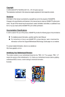
Directive Statement GIGABYTE products have not intended to add and safe from hazardous substances (Cd, Pb, Hg , your household waste disposal service or where you purchased the listed in your product's user's manual and we will be glad to help you with your effort. GA-73PVM-S2H Motherboard - 94 - Gigabyte GA-73PVM-S2H | Manual - Page 95
Finally, we suggest that you practice other environmentally friendly actions by understanding and using the energy-saving features of this product (where applicable), recycling the inner and outer packaging (including shipping containers) this product was delivered in, and by disposing of or - Gigabyte GA-73PVM-S2H | Manual - Page 96
GA-73PVM-S2H Motherboard - 96 - - Gigabyte GA-73PVM-S2H | Manual - Page 97
- 97 - Appendix - Gigabyte GA-73PVM-S2H | Manual - Page 98
GA-73PVM-S2H Motherboard - 98 - - Gigabyte GA-73PVM-S2H | Manual - Page 99
231, Taiwan TEL: +886-2-8912-4888 FAX: +886-2-8912-4003 Tech. and Non-Tech. Support (Sales/Marketing) : http://ggts.gigabyte.com.tw WEB address (English): http://www.gigabyte.com.tw WEB address (Chinese): http://www.gigabyte.tw G.B.T. INC. - U.S.A. TEL: +1-626-854-9338 FAX: +1-626-854-9339 Tech - Gigabyte GA-73PVM-S2H | Manual - Page 100
language in the language list on the top right corner of the website. GIGABYTE Global Service System To submit a technical or non-technical (Sales/ Marketing) question, please link to : http://ggts.gigabyte.com.tw Then select your language to enter the system. GA-73PVM-S2H Motherboard - 100 -
-
 1
1 -
 2
2 -
 3
3 -
 4
4 -
 5
5 -
 6
6 -
 7
7 -
8
-
9
-
10
-
11
-
12
-
13
-
14
-
15
-
16
-
17
-
18
-
19
-
20
-
21
-
22
-
23
-
24
-
25
-
26
-
27
-
28
-
29
-
30
-
31
-
32
-
33
-
34
-
35
-
36
-
37
-
38
-
39
-
40
-
41
-
42
-
43
-
44
-
45
-
46
-
47
-
48
-
49
-
50
-
51
-
52
-
53
-
54
-
55
-
56
-
57
-
58
-
59
-
60
-
61
-
62
-
63
-
64
-
65
-
66
-
67
-
68
-
69
-
70
-
71
-
72
-
73
-
74
-
75
-
76
-
77
-
78
-
79
-
80
-
81
-
82
-
83
-
84
-
85
-
86
-
87
-
88
-
89
-
90
-
91
-
92
-
93
-
94
-
95
-
96
-
97
-
98
-
99
-
100
 |
 |

GA-73PVM-S2H
LGA775 socket motherboard for Intel
®
Core
TM
processor family/
Intel
®
Pentium
®
processor family/Intel
®
Celeron
®
processor family
User's Manual
Rev. 1004
12ME-73PVMS2H-1004R