Gigabyte GA-73VM-S2 Manual
Gigabyte GA-73VM-S2 Manual
 |
View all Gigabyte GA-73VM-S2 manuals
Add to My Manuals
Save this manual to your list of manuals |
Gigabyte GA-73VM-S2 manual content summary:
- Gigabyte GA-73VM-S2 | Manual - Page 1
GA-73VM-S2 LGA775 socket motherboard for Intel® CoreTM processor family/ Intel® Pentium® processor family/Intel® Celeron® processor family User's Manual Rev. 1003 12ME-73VMS2-1003R - Gigabyte GA-73VM-S2 | Manual - Page 2
Motherboard GA-73VM-S2 Nov. 14, 2007 Motherboard GA-73VM-S2 Nov. 14, 2007 - Gigabyte GA-73VM-S2 | Manual - Page 3
of documentations: „ For detailed product information, carefully read the User's Manual. „ For instructions on how to use GIGABYTE's unique features, read or download the information on/from the Support\Motherboard\Technology Guide page on our website. For product-related information, check on our - Gigabyte GA-73VM-S2 | Manual - Page 4
...6 GA-73VM-S2 Motherboard Layout 7 Block Diagram...8 Chapter 1 Hardware Installation 9 1-1 Installation Precautions 9 1-2 Product Specifications 10 1-3 Installing the CPU and CPU Cooler 13 1-3-1 Installing the CPU 13 1-3-2 Installing the CPU Cooler 15 1-4 Installing the Memory 16 - Gigabyte GA-73VM-S2 | Manual - Page 5
Chipset Drivers 53 3-2 Software Applications 54 3-3 Driver CD Information 54 3-4 Hardware Information 55 3-5 Contact Us ...55 Chapter 4 Unique Features 57 4-1 Xpress Recovery2 57 4-2 BIOS Update Utilities 62 4-2-1 Updating the BIOS with the Q-Flash Utility 62 4-2-2 Updating the BIOS - Gigabyte GA-73VM-S2 | Manual - Page 6
Box Contents GA-73VM-S2 motherboard Motherboard driver disk User's Manual Intel® LGA775 CPU Installation Guide One IDE cable and one floppy disk drive cable Two SATA 3Gb/s cables I/O Shield • The box contents above are for reference only and the actual items shall depend on product package you - Gigabyte GA-73VM-S2 | Manual - Page 7
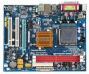
GA-73VM-S2 Motherboard Layout COMA KB_MS ATX_12V CPU_FAN LGA775 DDRII1 DDRII2 LPT LAN VGA GA-73VM-S2 R_USB USB RTL8201N AUDIO F_AUDIO BIOS CLR_CMOS PCIE_1 NVIDIA® GeForce 7050/ nForce 610i IT8718 PCIE_16 PCI1 SPDIF_O CODEC CD_IN PCI2 F_USB1 FDD F_USB2 SATAII0 SATAII2 SATAII1 - Gigabyte GA-73VM-S2 | Manual - Page 8
LGA775 Processor CPU CLK+/(333/266/200 MHz) PCIe CLK (100 MHz) D-Sub Host Interface DDR2 800/667/533 MHz PCI Express x16 1 PCI Express x1 PCIe CLK (100 MHz) x1 PCI Express Bus PCI Bus ATA-133/100/66/33 IDE Channel 4 SATA 3Gb/s NVIDIA® GeForce 7050/ nForce 610i 8 USB Ports RTL 8201N LAN - Gigabyte GA-73VM-S2 | Manual - Page 9
's manual and follow these procedures: • Prior to installation, do not remove or break motherboard S/N wrist strap when handling electronic components such as a motherboard, CPU or memory. If you do not have an ESD wrist steps or have a problem related to the use of the product, please consult - Gigabyte GA-73VM-S2 | Manual - Page 10
CPU Front Side Bus Chipset Memory Onboard Graphics Audio LAN Expansion Slots Storage Interface USB Š Support for an Intel® CoreTM 2 Extreme processor/ Intel® CoreTM 2 Quad processor/Intel® CoreTM 2 Duo processor/ Intel® Pentium® processor Extreme Edition/Intel® Pentium® D processor/ Intel - Gigabyte GA-73VM-S2 | Manual - Page 11
connector Š 1 x floppy disk drive connector Š 1 x IDE connector Š 4 x SATA 3Gb/s connectors Š 1 x CPU fan header Š 1 x system fan header Š 1 x front panel header Š 1 x front panel audio header Š 1 x CD In connector Š 1 x S/PDIF Out header Š 2 x USB 2.0/1.1 headers Š 1 x chassis intrusion - Gigabyte GA-73VM-S2 | Manual - Page 12
Install Š Support for Xpress Recovery2 Š Support for Virtual Dual BIOS Š Norton Internet Security (OEM version) Š Support for Microsoft® Windows® Vista/XP Š Micro ATX Form Factor; 24.4cm x 19.4cm (Note) Available functions in Easytune may differ by motherboard model. GA-73VM-S2 Motherboard - 12 - Gigabyte GA-73VM-S2 | Manual - Page 13
so according to your hardware specifications including the CPU, graphics card, memory, hard drive, etc. 1-3-1 Installing the CPU A. Locate the alignment keys on the motherboard CPU socket and the notches on the CPU. LGA775 CPU Socket Alignment Key LGA 775 CPU Alignment Key Pin One Corner of the - Gigabyte GA-73VM-S2 | Manual - Page 14
pin one corner of the CPU socket (or you may align the CPU notches with the socket alignment keys) and gently insert the CPU into position. Step 5: Once the CPU is properly inserted, replace the load plate and push the CPU socket lever back into its locked position. GA-73VM-S2 Motherboard - 14 - - Gigabyte GA-73VM-S2 | Manual - Page 15
. Check that the Male and Female push pins are joined closely. (Refer to your CPU cooler installation manual for instructions on installing the cooler.) Step 5: After the installation, check the back of the motherboard. If the push pin is inserted as the picture above, the installation is complete - Gigabyte GA-73VM-S2 | Manual - Page 16
in the picture on the left, place your fingers on the top edge of the memory, push down on the memory and insert it vertically into the memory socket. Step 2: The clips at both ends of the socket will snap into place when the memory module is securely inserted. GA-73VM-S2 Motherboard - 16 - - Gigabyte GA-73VM-S2 | Manual - Page 17
an expansion card: • Make sure the motherboard supports the expansion card. Carefully read the manual that came with your expansion card. • Always If necessary, go to BIOS Setup to make any required BIOS changes for your expansion card(s). 7. Install the driver provided with the expansion card - Gigabyte GA-73VM-S2 | Manual - Page 18
. Connect a monitor that supports D-Sub connection to this port. USB Port The USB port supports the USB 2.0/1.1 specification. Use this port for USB devices such as an USB keyboard/mouse, USB printer, USB flash drive and etc. RJ-45 LAN Port The Fast Ethernet LAN port provides Internet connection - Gigabyte GA-73VM-S2 | Manual - Page 19
to connect front speakers in a 4/5.1-channel audio configuration. Mic In Jack (Pink) The default Mic in jack. Microphones must be connected to this jack. Refer to the instructions on setting up a 2/4/5.1-channel audio configuration in Chapter 5, "Configuring 2/4/5.1-Channel Audio." - 19 - Hardware - Gigabyte GA-73VM-S2 | Manual - Page 20
devices. • After installing the device and before turning on the computer, make sure the device cable has been securely attached to the connector on the motherboard. - 20 - Hardware Installation - Gigabyte GA-73VM-S2 | Manual - Page 21
supply can supply enough stable power to all the components on the motherboard. Before connecting the power connector, first make sure the power supply the correct orientation. The 12V power connector mainly supplies power to the CPU. If the 12V power connector is not connected, the computer will - Gigabyte GA-73VM-S2 | Manual - Page 22
drives supported are: 360 KB, 720 KB, 1.2 MB, 1.44 MB, and 2.88 MB. Before connecting a floppy disk drive, be sure to locate pin 1 of the connector and the floppy disk drive cable. The pin 1 of the cable is typically designated by a stripe of different color. 33 1 34 2 GA-73VM-S2 Motherboard - Gigabyte GA-73VM-S2 | Manual - Page 23
compatible with SATA 1.5Gb/s standard. Each SATA connector supports a single SATA device. The NVIDIA® GeForce 7050/ nForce 610i controller supports RAID 0 and RAID 1. Refer to Chapter 5, "Configuring SATA Hard Drive(s)," for instructions on configuring a RAID array. 1 Pin No. 1 Definition GND - Gigabyte GA-73VM-S2 | Manual - Page 24
S3/S4/S5 Off 9) BAT(BATTERY) The battery provides power to keep the values (such as BIOS configurations, date, and time information) in the CMOS when the computer is turned off. Replace the must be handled in accordance with local environmental regulations. GA-73VM-S2 Motherboard - 24 - - Gigabyte GA-73VM-S2 | Manual - Page 25
is detected at system startup. If a problem is detected, the BIOS may issue beeps in different patterns to indicate the problem. Refer to Chapter 5, "Troubleshooting," for information about beep codes. • HD (IDE Hard Drive Activity LED) Connects to the hard drive activity LED on the chassis front - Gigabyte GA-73VM-S2 | Manual - Page 26
front panel audio module that has different wire assignments, please contact the chassis manufacturer. 12) CD_IN (CD In Connector) You may connect the audio cable that came with your optical drive to the header. 1 Pin No. Definition 1 CD-L 2 GND 3 GND 4 CD-R GA-73VM-S2 Motherboard - 26 - Gigabyte GA-73VM-S2 | Manual - Page 27
PDIF out cable, this header can connect to an audio device that supports digital audio in. For purchasing the optional S/PDIF out cable USB Headers) The headers conform to USB 2.0/1.1 specification. Each USB header can provide two USB ports via an optional USB bracket. For purchasing the optional USB - Gigabyte GA-73VM-S2 | Manual - Page 28
," for BIOS configurations). 16) CI (Chassis Intrusion Header) This motherboard provides a chassis detection feature that detects if the chassis cover has been removed. This function requires a chassis with chassis intrusion detection design. Pin No. Definition 1 Signal 1 2 GND GA-73VM-S2 - Gigabyte GA-73VM-S2 | Manual - Page 29
the GIGABYTE Q-Flash or @BIOS utility. • Q-Flash allows the user to quickly and easily upgrade or back up BIOS without entering the operating system. • @BIOS is a Windows-based utility that searches and downloads the latest version of BIOS from the Internet and updates the BIOS. For instructions on - Gigabyte GA-73VM-S2 | Manual - Page 30
Screen The following screen may appear when the computer boots. Motherboard Model BIOS Version Award Modular BIOS v6.00PG, An Energy Star Ally Copyright (C) 1984-2007, Award Software, Inc. GA-73VM-S2 F1a . . . . : BIOS Setup/Q-Flash : XpressRecovery2 : Boot Menu : Qflash 10 - Gigabyte GA-73VM-S2 | Manual - Page 31
among the items and press to accept or enter a sub-menu. (Sample BIOS Version:F1a) CMOS Setup Utility-Copyright (C) 1984-2007 Award Software ` Standard CMOS Features ` Advanced BIOS Features ` Integrated Peripherals ` Power Management Setup ` PnP/PCI Configurations ` PC Health Status ` MB - Gigabyte GA-73VM-S2 | Manual - Page 32
CMOS and exit BIOS Setup. (Pressing can also carry out this task.) „ Exit Without Saving Abandon all changes and the previous settings remain in effect. Pressing to the confirmation message will exit BIOS Setup. (Pressing can also carry out this task.) GA-73VM-S2 Motherboard - 32 - - Gigabyte GA-73VM-S2 | Manual - Page 33
` ` IDE Channel 0 Master ` IDE Channel 0 Slave ` IDE Channel 2 Master ` IDE Channel 2 Slave ` IDE Channel 3 Master ` IDE Channel 3 Slave [None] [None] [None] [None] [None] [None] Drive A Floppy 3 Mode Support Halt On [1.44M, 3.5"] [Disabled] [All, But Keyboard] Base Memory Extended Memory 640K - Gigabyte GA-73VM-S2 | Manual - Page 34
will stop for all other errors. Memory These fields are read-only and are determined by the BIOS POST. Base Memory Also called conventional memory. Typically, 640 KB will be reserved for the MS-DOS operating system. Extended Memory The amount of extended memory. GA-73VM-S2 Motherboard - 34 - - Gigabyte GA-73VM-S2 | Manual - Page 35
hard drive and to issue warnings when a third party hardware monitor utility is installed. (Default: Disabled) (Note) This item is present only if you install a CPU that supports this feature. For more information about Intel CPUs' unique features, please visit Intel's website. - 35 - BIOS Setup - Gigabyte GA-73VM-S2 | Manual - Page 36
is installed. If you wish to set up a dual view configuration, set this item to Always Enable. (Note) This item is present only if you install a CPU that supports this feature. For more information about Intel CPUs' unique features, please visit Intel's website. GA-73VM-S2 Motherboard - 36 - - Gigabyte GA-73VM-S2 | Manual - Page 37
allocated solely for the onboard graphics controller. MS-DOS, for example, will use only this memory for display. Options are: 64M, 128M (default), 256M, Disabled. Init Display First Specifies the as the first display. PEG Sets PCI Express graphics card as the first display. - 37 - BIOS Setup - Gigabyte GA-73VM-S2 | Manual - Page 38
1984-2007 Award Software Integrated Peripherals On-Chip IDE Channel0 IDE Prefetch Mode NV Serial-ATA Controller ` SATA-II RAID Config On-Chip MAC Lan Onboard LAN Boot ROM Onboard Audio Function On-Chip USB USB Memory Type USB Keyboard Support USB Mouse Support ` SMART LAN Legacy USB storage detect - Gigabyte GA-73VM-S2 | Manual - Page 39
Memory Type Specifies the type of memory allocated for USB devices. Options are: SHADOW (default), Base Memory (640K). USB Keyboard Support Allows USB keyboard to be used in MS-DOS. (Default: Disabled) USB Mouse Support Allows USB mouse to be used in MS-DOS. (Default: Disabled) - 39 - BIOS - Gigabyte GA-73VM-S2 | Manual - Page 40
) CMOS Setup Utility-Copyright (C) 1984-2007 Award Software SMART LAN Start detecting at Port..... Pair1-2 Status = Open /100/1000Mbps in Windows mode or when the LAN Boot ROM is activated. When a Cable Problem Occurs... If a cable problem occurs on a LAN cable. GA-73VM-S2 Motherboard - 40 - - Gigabyte GA-73VM-S2 | Manual - Page 41
detect Determines whether to detect USB storage devices, including USB flash drives and USB hard drives during the POST. (Default: Port), ECP (Extended Capabilities Port), ECP+EPP. ECP Mode Use DMA Selects DMA channel for the LPT port in ECP mode. This item is configurable only if Parallel Port - Gigabyte GA-73VM-S2 | Manual - Page 42
a modem that supports wake-up function. (Default: Enabled) USB Resume from Suspend Allows the system to be awakened from ACPI S3 sleep state by a wake-up signal from the installed USB device. (Default: Disabled ) (Note) Supported on Windows® Vista® operating system only. GA-73VM-S2 Motherboard - Gigabyte GA-73VM-S2 | Manual - Page 43
AC power, or the settings may not be effective. HPET Support (Note) Enables or disables High Precision Event Timer (HPET) for Windows® Vista® operating system. (Default: Enabled) Power On By the return of the AC power. (Note) Supported on Windows® Vista® operating system only. - 43 - BIOS Setup - Gigabyte GA-73VM-S2 | Manual - Page 44
1984-2007 Award Software PnP/PCI BIOS auto-assigns IRQ to the first PCI slot. (Default) Assigns IRQ 3,4,5,7,9,10,11,12,14,15 to the first PCI slot. BIOS auto-assigns IRQ to the second PCI slot. (Default) Assigns IRQ 3,4,5,7,9,10,11,12,14,15 to the second PCI slot. GA-73VM-S2 Motherboard - Gigabyte GA-73VM-S2 | Manual - Page 45
Software PC Health Status Reset Case Open Status Case Opened Vcore DDR2 1.8V +3.3V +12V Current System Temperature Current CPU Temperature Current CPU FAN Speed Current SYSTEM FAN Speed CPU Warning Temperature CPU intrusion detection device attached to the motherboard CI header. If the system - Gigabyte GA-73VM-S2 | Manual - Page 46
is configurable only if CPU Smart FAN Control is set to Enabled. Auto Lets BIOS autodetect the type of CPU fan installed and sets the optimal CPU fan control mode. (Default) Voltage Sets Voltage mode for a 3-pin CPU fan. PWM Sets PWM mode for a 4-pin CPU fan. GA-73VM-S2 Motherboard - 46 - - Gigabyte GA-73VM-S2 | Manual - Page 47
Value Displays the following CPU and memory speed. Setting shows the value you manually adjust; Current Value shows the current operating frequency. Current CPU Freq, MHz Displays the CPU speeds. (Note) This item appears only if you install a CPU that supports this feature. - 47 - BIOS Setup - Gigabyte GA-73VM-S2 | Manual - Page 48
can be increased by 1% ~ 50%. CPU Clock Ratio (Note) Allows you to alter the clock ratio for the installed CPU. The item is present only if a CPU with unlocked clock ratio is installed. (Note) This item appears only if you install a CPU that supports this feature. GA-73VM-S2 Motherboard - 48 - - Gigabyte GA-73VM-S2 | Manual - Page 49
the CPU voltage as required. The adjustable range is dependent on the CPU being installed. (Default: Normal) Note: Increasing CPU voltage may result in damage to your CPU or reduce the useful life of the CPU. Normal CPU Vcore Displays the normal operating voltage of your CPU. - 49 - BIOS Setup - Gigabyte GA-73VM-S2 | Manual - Page 50
Software ` Standard CMOS Features Load Fail-Safe Defaults ` Advanced BIOS Features BIOS default settings. The BIOS defaults settings helps the system to operate in optimum state. Always load the Optimized defaults after updating the BIOS or after clearing the CMOS values. GA-73VM-S2 Motherboard - Gigabyte GA-73VM-S2 | Manual - Page 51
2-12 Set Supervisor/User Password CMOS Setup Utility-Copyright (C) 1984-2007 Award Software ` Standard CMOS Features ` Advanced BIOS Features ` Integrated Peripherals ` Power Management Setup ` PnP/PCI ConfiguratioEnns ter Password: ` PC Health Status ` MB Intelligent Tweaker(M.I.T.) Esc: Quit F8: - Gigabyte GA-73VM-S2 | Manual - Page 52
Setup Utility-Copyright (C) 1984-2007 Award Software ` Standard CMOS Features ` Advanced BIOS Features ` Integrated Peripherals ` Power the BIOS Setup without saving the changes made in BIOS Setup to the CMOS. Press or to return to the BIOS Setup Main Menu. GA-73VM-S2 Motherboard - 52 - - Gigabyte GA-73VM-S2 | Manual - Page 53
for installation of the RAID controller driver, please insert the motherboard driver disk and select to install the driver automatically in the dialog box. • For USB 2.0 driver support under the Windows XP operating system, please install the Windows XP Service Pack 1 or later. After installing the - Gigabyte GA-73VM-S2 | Manual - Page 54
all the tools and applications that GIGABYTE develops and some free software. You may press the Install button following an item to install it. 3-3 Driver CD Information This page provides information about the drivers, applications and tools in this driver disk. GA-73VM-S2 Motherboard - 54 - - Gigabyte GA-73VM-S2 | Manual - Page 55
3-4 Hardware Information This page provides information about the hardware devices on this motherboard. 3-5 Contact Us Check the contacts information of the GIGABYTE headquarter in Taiwan and the overseas branch offices on the last page of this manual. - 55 - Drivers Installation - Gigabyte GA-73VM-S2 | Manual - Page 56
GA-73VM-S2 Motherboard - 56 - - Gigabyte GA-73VM-S2 | Manual - Page 57
backed up/restored. • It takes longer to back up a hard drive than to restore it. System Requirements: • Intel® x86 platform • At least 64 MB of system memory • VESA compatible graphics card • Windows® 2000 with SP3 or later; Windows® XP with SP1 or later • Xpress Recovery and Xpress Recovery2 are - Gigabyte GA-73VM-S2 | Manual - Page 58
Windows XP as the example operating system.) A. Installing Windows XP and Partitioning the Hard Drive 1. Set CD-ROM drive as the first boot device under "Advanced BIOS Features" in the BIOS NTFS) and begin the installation of the operating system (Figure 3). Figure 3 GA-73VM-S2 Motherboard - 58 - - Gigabyte GA-73VM-S2 | Manual - Page 59
not be able to create new partitions or use Xpress Recovery2. If this occurs, reinstall the operating system and re-partition your hard drive. Figure 6 In the New Partition Wizard, you MUST select Primary partition. This will reserve unallocated space for Xpress Recovery2 to use. Figure 7 - 59 - Gigabyte GA-73VM-S2 | Manual - Page 60
hard drive contains the Windows operating system. When the Windows operating system is detected, Xpress Recovery2 will begin the backup process (Figure 11). Figure 10 Figure 11 3. When finished, go to Disk Management to check disk allocation. Figure 12 GA-73VM-S2 Motherboard Xpress Recovery2 - Gigabyte GA-73VM-S2 | Manual - Page 61
backup file, select REMOVE (Figure 15). 2. After the backup file is removed, no backup image file will be present in Disk Management and hard drive space will be freed up (Figure 16). Figure 15 F. Exiting Xpress Recovery2 Select REBOOT to exit Xpress Recovery2. Figure 16 Figure 17 - 61 - Unique - Gigabyte GA-73VM-S2 | Manual - Page 62
You Begin: 1. From GIGABYTE's website, download the latest compressed BIOS update file that matches your motherboard model. 2. Extract the file and save the new BIOS file (e.g. 73VMS2.f1) to your floppy disk, USB flash drive, or hard drive. Note: The USB flash drive or hard drive must use FAT32/16 - Gigabyte GA-73VM-S2 | Manual - Page 63
down arrow key to select Update BIOS from Drive and press . • The Save Main BIOS to Drive option allows you to save the current BIOS file. • Q-Flash only supports USB flash drive or hard drives using FAT32/16/12 file system. • If the BIOS update file is saved to a hard drive in RAID/AHCI mode - Gigabyte GA-73VM-S2 | Manual - Page 64
Quit F8: Q-Flash KLJI: Select Item F10: Save & Exit Setup Load Optimized Defaults Press to load BIOS defaults Step 6: Select Save & Exit Setup and then press to save settings to CMOS and exit BIOS Setup. The procedure is complete after the system restarts. GA-73VM-S2 Motherboard - 64 - - Gigabyte GA-73VM-S2 | Manual - Page 65
and Using @BIOS: Use the motherboard driver disk included with the motherboard to install @BIOS. • Installing the @BIOS utility. • Accessing the @BIOS utility. Click Start>All Programs>GIGABYTE>@BIOS Select @BIOS and click Install. C. Options and Instructions: 1. Save the Current BIOS File In - Gigabyte GA-73VM-S2 | Manual - Page 66
in an unbootable system. • If the BIOS update file for your motherboard is not present on the @BIOS server site, please manually download the BIOS update file from GIGABYTE's website and follow the instructions in "Update the BIOS without Using the Internet Update Function" below. Step 4: As the - Gigabyte GA-73VM-S2 | Manual - Page 67
the BIOS Setup program. EasyTune 5 provides the following functions (Note 1): overclocking/overvoltage, C.I.A./ M.I.B. (Note 2), smart fan control, and hardware monitoring and warning. (For instructions on using EasyTune5, read or download the information on/from the Support\Motherboard\Utility - Gigabyte GA-73VM-S2 | Manual - Page 68
the slider or spin box. Click Apply and then OK to turn on ReadyBoost. • The USB flash drive must have at least 256 MB of space. • The recommended amount of memory to use for ReadyBoost acceleration is one to three times the amount of RAM installed in your computer. GA-73VM-S2 Motherboard - 68 - - Gigabyte GA-73VM-S2 | Manual - Page 69
do not want to create RAID, you may prepare only one hard drive. • An empty formatted floppy disk. • Windows Vista/XP setup disk. • Motherboard driver disk.(Note 3) 5-1-1 Configuring the Onboard SATA Controller A. Installing SATA hard drive(s) in your computer Attach one end of the SATA signal cable - Gigabyte GA-73VM-S2 | Manual - Page 70
1984-2007 Award Software Integrated Peripherals On-Chip IDE Channel0 IDE Prefetch Mode NV Serial-ATA Controller ` SATA-II RAID Config On-Chip MAC Lan Onboard LAN Boot ROM Onboard Audio Function On-Chip USB USB Memory Type USB Keyboard Support USB Mouse Support ` SMART LAN Legacy USB storage detect - Gigabyte GA-73VM-S2 | Manual - Page 71
BIOS Enter the RAID BIOS setup utility to configure a RAID array. For a non-RAID configuration, please skip this step and proceed to the installation of Windows operating system. Step 1: After the POST memory RAID mode. The supported RAID modes include selected, you can manually set the stripe block - Gigabyte GA-73VM-S2 | Manual - Page 72
clear or to abort. (We recommend that you clear the MBR to reduce drive errors.) RAID Mode: Striped MediaShield BIOS Jul 27 2007 - Define a New Array - Stripe Block: Optimal Free Disks Port ] Back [F7] Finish [TAB] Navigate [KL] Select [ENTER] Popup Figure 6 GA-73VM-S2 Motherboard - 72 - - Gigabyte GA-73VM-S2 | Manual - Page 73
for BIOS Boot Specification. This indicates that the boot device is defined in the BIOS.) Boot BBS MediaShield BIOS Jul including the RAID mode, stripe block size, hard drive model name, and hard drive capacity, etc. RAID Mode: Striped Stripe Width : driver and operating system. - 73 - Appendix - Gigabyte GA-73VM-S2 | Manual - Page 74
users without a startup disk: Use an alternative system and insert the motherboard driver disk. From your optical drive folder, double click the MENU. exe file in the BootDrv folder (Figure 3).A command prompt window will open similar to that in Figure 2. GA-73VM-S2 Motherboard Figure 3 - 74 - - Gigabyte GA-73VM-S2 | Manual - Page 75
System Now that you have prepared the SATA RAID/AHCI driver diskette and configured the required BIOS settings, you are ready to install Windows Vista/XP onto your hard drive(s). A. Installing Windows XP Step 1: Restart your system to boot from the Windows XP setup disk and press as soon as you - Gigabyte GA-73VM-S2 | Manual - Page 76
saying one or some file(s) cannot be found, please check the floppy disk or copy the correct SATA RAID driver again from the motherboard driver disk. (Note) The selectable item(s) displayed in Figure 3 may differ according to the RAID or AHCI driver you will install. GA-73VM-S2 Motherboard - 76 - - Gigabyte GA-73VM-S2 | Manual - Page 77
specify additional mass storage devices for use with Windows, press ENTER. S=Specify Additional Device ENTER=Continue F3=Exit Figure 5 Step 4: After the SATA controller driver installation is completed, you can proceed with the Windows XP installation. WindowsXP Professional Setup Welcome to Setup - Gigabyte GA-73VM-S2 | Manual - Page 78
.exe file to extract the driver files. Finally, insert the floppy disk and browse to the floppy disk.) Figure 8 (Note) For AHCI drives, installation of Windows Vista does not require you to install the SATA AHCI driver in advance during the OS installation process. GA-73VM-S2 Motherboard - 78 - - Gigabyte GA-73VM-S2 | Manual - Page 79
a screen as shown in Figure 9 appears, select NVIDIA nForce RAID Controller and press Next. Figure 9 Step 4: After the driver is loaded, the screen will show the RAID hard drive. Select the RAID hard drive onto which you want to install the operating system and then press Next to continue the OS - Gigabyte GA-73VM-S2 | Manual - Page 80
. Before installing the audio driver, make sure the "Microsoft UAA Bus driver for High Definition Audio" has been installed from the motherboard driver disk and your operating system has been updated with the latest Service Pack for Windows. (Note) 2/4/5.1-Channel Audio Configurations: Refer to - Gigabyte GA-73VM-S2 | Manual - Page 81
The pictures to the right show the 2-, 4-, 5.1-channel speaker configurations. 2-Channel Speakers: 4-Channel Speakers: Speakers or Headphones Front Speaker Out Rear Speaker Out 5.1-Channel Speakers: Step 4: Everytime you connect an audio device to an audio jack, the Connected device box appears - Gigabyte GA-73VM-S2 | Manual - Page 82
Disable front panel jack detection check box. Click OK to activiate the AC'97 functionality. When using an AC'97 front panel audio module, you can only have audio signals present on either the front or the back panel audio connections, but not both at the same time. GA-73VM-S2 Motherboard - 82 - - Gigabyte GA-73VM-S2 | Manual - Page 83
in and out cable first if you want to output S/PDIF digital audio signals to an external decoder. A. Installing the S/PDIF Out Cable: Step 1: First, attach the connector at the end of the cable to the SPDIF_O header on your motherboard. Pin 1 (the red wire) of the S/PDIF out cable must align - Gigabyte GA-73VM-S2 | Manual - Page 84
PDIF digital audio signals. S/PDIF Optical Cable B. Configuring S/PDIF out: Click the tool icon in the DIGITAL section. In the S/PDIF Settings dialog box, select an output sampling rate and select (or disable) the output source. Click OK to complete the configuration. GA-73VM-S2 Motherboard - 84 - Gigabyte GA-73VM-S2 | Manual - Page 85
5-2-3 Configuring Microphone Recording Step 1: After installing the audio driver, the Audio Manager icon will appear in your system tray. Double-click the icon to access the Audio Control Panel. Step 2: Connect your microphone to the Mic in jack (pink) on the back panel or the Line in jack on the - Gigabyte GA-73VM-S2 | Manual - Page 86
list, select Realtek HD Audio Input. Then set the recording sound level properly. Do NOT mute the recording sound, or you will not hear any sound when playing back the recording you just made. Select Realtek HD Audio Input in the Mixer device list GA-73VM-S2 Motherboard Recording Control - 86 - - Gigabyte GA-73VM-S2 | Manual - Page 87
, and then click Sound Recorder to begin the sound recording. 5-2-4 Using the Sound Recorder Recording the Sound: 1. Make sure you have connected the audio input device (e.g. microphone) to the computer. 2. On the File menu, choose New. 3. To record a sound file, click the Recording but- ton . 4. To - Gigabyte GA-73VM-S2 | Manual - Page 88
setting error 1 long, 1 short: Memory or motherboard error 1 long, 2 short: Monitor or graphics card error 1 long, 3 short: Keyboard error 1 long, 9 short: BIOS ROM error Continuous long beeps: Graphics card not inserted properly Continuous short beeps: Power error GA-73VM-S2 Motherboard - 88 - - Gigabyte GA-73VM-S2 | Manual - Page 89
any troubles during system startup, follow the troubleshooting procedure below to solve the problem. START Turn off the power. Remove all peripherals, connecting cables, and power cord etc. Make sure the motherboard does not short-circuit with the chassis or other metal objects. No Check if the CPU - Gigabyte GA-73VM-S2 | Manual - Page 90
and solved. END If the procedure above is unable to solve your problem, contact the place of purchase or local dealer for help. Or go to the Support\Technical Service Zone page to submit your question. Our customer service staff will reply you as soon as possible. GA-73VM-S2 Motherboard - 90 - - Gigabyte GA-73VM-S2 | Manual - Page 91
GIGABYTE. Our Commitment to Preserving the Environment In addition to high-efficiency performance, all GIGABYTE motherboards local government office, your household waste disposal service or where you purchased the product for user's manual and we will be glad to help you with your effort. - - Gigabyte GA-73VM-S2 | Manual - Page 92
disposed of properly. China Restriction of Hazardous Substances Table The following table is supplied in compliance with China's Restriction of Hazardous Substances (China RoHS) requirements: GA-73VM-S2 Motherboard - 92 - - Gigabyte GA-73VM-S2 | Manual - Page 93
- 93 - Appendix - Gigabyte GA-73VM-S2 | Manual - Page 94
GA-73VM-S2 Motherboard - 94 - - Gigabyte GA-73VM-S2 | Manual - Page 95
(Soporte de habla hispano) FAX: +1-626-854-9339 Correo: [email protected] Tech. Support: http://rma.gigabyte-usa.com Web address: http://www.gigabyte.com.mx Singapore GIGA-BYTE SINGAPORE PTE. LTD. WEB address : http://www.gigabyte.sg Thailand WEB address : http://th.giga-byte.com Vietnam WEB - Gigabyte GA-73VM-S2 | Manual - Page 96
your language in the language list on the top right corner of the website. GIGABYTE Global Service System To submit a technical or non-technical (Sales/ Marketing) question, please link to : http://ggts.gigabyte.com.tw Then select your language to enter the system. GA-73VM-S2 Motherboard - 96 -
-
 1
1 -
 2
2 -
 3
3 -
 4
4 -
 5
5 -
 6
6 -
 7
7 -
8
-
9
-
10
-
11
-
12
-
13
-
14
-
15
-
16
-
17
-
18
-
19
-
20
-
21
-
22
-
23
-
24
-
25
-
26
-
27
-
28
-
29
-
30
-
31
-
32
-
33
-
34
-
35
-
36
-
37
-
38
-
39
-
40
-
41
-
42
-
43
-
44
-
45
-
46
-
47
-
48
-
49
-
50
-
51
-
52
-
53
-
54
-
55
-
56
-
57
-
58
-
59
-
60
-
61
-
62
-
63
-
64
-
65
-
66
-
67
-
68
-
69
-
70
-
71
-
72
-
73
-
74
-
75
-
76
-
77
-
78
-
79
-
80
-
81
-
82
-
83
-
84
-
85
-
86
-
87
-
88
-
89
-
90
-
91
-
92
-
93
-
94
-
95
-
96
 |
 |

GA-73VM-S2
LGA775 socket motherboard for Intel
®
Core
TM
processor family/
Intel
®
Pentium
®
processor family/Intel
®
Celeron
®
processor family
User's Manual
Rev. 100
3
12ME-73VMS2-100
3
R