Gigabyte GA-78LMT-USB3 Manual - Page 18
F_PANEL Front Panel Header, Speaker, MSG/PWR - beep codes
 |
View all Gigabyte GA-78LMT-USB3 manuals
Add to My Manuals
Save this manual to your list of manuals |
Page 18 highlights
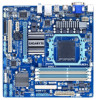
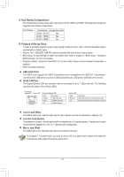
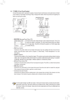
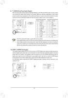
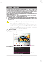
8) F_PANEL (Front Panel Header) Connect the power switch, reset switch, speaker, chassis intrusion switch/sensor and system status indicator on the chassis to this header according to the pin assignments below. Note the positive and negative pins before connecting the cables. Message/Power/ Power Sleep LED Switch Speaker MSG+ MSG- PW+ PWSPEAK+ SPEAK- F_AUDIO(H) F_PANEL(NH) 2 1 20 F_PANEL 19 (H61M-D2) HD+ HD- RESRES+ CICI+ PWR+ PWR- Hard Drive Activity LED Reset Power LED Switch Chassis Intrusion Header DB_PORT •• MSG/PWR (Message/Power/Sleep LED): System Status LED Connects to the power status indicator on the chassis front panel. The LED is S0 On BIOS Swointchwerh(Xe5n8Ath-OeCs) ystem is operating. The LED keeps blinking when the system S1 Blinking 1 is in S1 sleep state. The LED is off when the system is in S3/S4 sleep state S3/S4/S5 Off or powered off (SM5_).SATA DIP 1 23 1 DIP 1 23 1 DIP 1 23 1 •• PW (Power Switch): Connects to the power switch on the chassis front panel. You may configure the way to tAuCrPnI_oCfPfTyour Voltage measurement msoydsutlee(mX58uAs-OinCg) the power switch (refer to Chapter 2, "BIOS Setup," "Power Managemen(tG,"A-fIoVBr )more information). PWM Switch (X58A-OC) •• Speaker (Speaker): Connects to the speaker on the chassis front panel. The system reports system startup status by issuing DIP a beep code. One single short 1 23 beep will be heard if no problem is detected at system startup.SIMf aB_pCrPoTblem is detected, the BIOS may issue beeps in different patterns to indicate the problem. (GA-IVB) PCIe power con•n•ecHtoDr (S(AHTaAr)(dX5D8Ari-vOeCA) ctivity LED): Connects to the hard drive activity LED on the chassis front panel. The LED is on when the hard drive is reading or writing data. •• RES (Reset Switch): CLR_CMOS Connects to the reset switch on the chassis front panel. Press the reset switch to restart thCeI computer if the computer freezes and fails to perform a normal restart. •• CI (Chassis Intrusion Header): DIS_ME GP15_CPT (GA-IVB) Connects to the chassis intrusion switch/sensor on the chassis that can detect if the chassis cover has nt points(G1.Sniper 3) been removed. This function requires a chassis with a chassis intrusion switch/sensor. BIOS Switcher (SW4) XDP_CPU XDP_PCH (GA-IVB) The front panel design may differ by chassis. A front panel module mainly consists of power switch, reset switch, power LED, hard drive activity LED, speaker and etc. When connecting your chassis front panel module to this header, make sure the wire assignments and the pin assignments are matched correctly. - 18 -
-
 1
1 -
2
-
3
-
4
-
5
-
6
-
7
-
8
-
9
-
10
-
11
-
12
-
 13
13 -
 14
14 -
 15
15 -
 16
16 -
 17
17 -
 18
18 -
 19
19 -
 20
20 -
 21
21 -
 22
22 -
 23
23 -
24
-
25
-
26
-
27
-
28
-
29
-
30
-
31
-
32
-
33
-
34
-
35
-
36
-
37
-
38
-
39
-
40
-
41
-
42
-
43
-
44
 |
 |