Gigabyte GA-790FXTA-UD5 Manual
Gigabyte GA-790FXTA-UD5 Manual
 |
UPC - 818313009289
View all Gigabyte GA-790FXTA-UD5 manuals
Add to My Manuals
Save this manual to your list of manuals |
Gigabyte GA-790FXTA-UD5 manual content summary:
- Gigabyte GA-790FXTA-UD5 | Manual - Page 1
GA-790FXTA-UD5 AM3 socket motherboard for AMD Phenom™ II processor/ AMD Athlon™ II processor User's Manual Rev. 1001 12ME-790FTA5-1001R - Gigabyte GA-790FXTA-UD5 | Manual - Page 2
Motherboard GA-790FXTA-UD5 Nov. 13, 2009 Motherboard GA-790FXTA-UD5 Nov. 13, 2009 - Gigabyte GA-790FXTA-UD5 | Manual - Page 3
the product. For detailed product information, carefully read the User's Manual. For instructions on how to use GIGABYTE's unique features, read or download the information on/from the Support&Downloads\Motherboard\Technology Guide page on our website. For product-related information, check on our - Gigabyte GA-790FXTA-UD5 | Manual - Page 4
Items...6 GA-790FXTA-UD5 Motherboard Layout 7 Block Diagram...8 Chapter 1 Hardware Installation 9 1-1 Installation Precautions 9 1-2 Product Specifications 10 1-3 Installing the CPU and CPU Cooler 13 1-3-1 Installing the CPU 13 1-3-2 Installing the CPU Cooler 15 1-4 Installing the Memory 16 - Gigabyte GA-790FXTA-UD5 | Manual - Page 5
79 5-1 Configuring SATA Hard Drive(s 79 5-1-1 Configuring AMD SB750 SATA Controller 79 5-1-2 Configuring JMicron JMB362 SATA Controller 85 5-1-3 Configuring Marvell 9128 SATA Controller 91 5-1-4 Making a SATA RAID/AHCI Driver Diskette 96 5-1-5 Installing the SATA RAID/AHCI Driver and Operating - Gigabyte GA-790FXTA-UD5 | Manual - Page 6
Box Contents GA-790FXTA-UD5 motherboard Motherboard driver disk User's Manual Quick Installation Guide One IDE cable Four SATA 3Gb/s cables I/O Shield • The box contents above are for reference only and the actual items shall depend on the product package you obtain. The box - Gigabyte GA-790FXTA-UD5 | Manual - Page 7
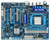
GA-790FXTA-UD5 Motherboard Layout KB_MS ATX_12V RCA_SPDIF USB_1394_ESATA_2 USB_1394_ESATA_1 CPU_FAN Socket AM3 USB_LAN USB30_LAN JMicron JMB362 AUDIO NEC F_AUDIO PCIEX1 RTL8111D NB_FAN AMD 790FX RTL8111D PCI1 GA-790FXTA-UD5 CODEC PCIEX16_1 PCIEX16_2 SPDIF_I PCI2 CD_IN SPDIF_O - Gigabyte GA-790FXTA-UD5 | Manual - Page 8
RTL8111D RJ45 1 PCI Express x1 LAN1 RJ45 LAN2 Dual BIOS PCI Bus TSB43AB23 CPU CLK+/- (200 MHz) AM3 CPU DDR3 1866 (O.C.) (Note)/1333/1066 MHz Dual Channel Memory Hyper Transport 3.0 JMicron JMB362 SATA 3Gb/s x1 PCIe CLK (100 MHz) AMD 790FX PCI Express Bus x1 2 USB 3.0/2.0 x1 NEC - Gigabyte GA-790FXTA-UD5 | Manual - Page 9
manual and follow these procedures: • Prior to installation, do not remove or break motherboard S/N motherboard, avoid touching any metal leads or connectors. • It is best to wear an electrostatic discharge (ESD) wrist strap when handling electronic com- ponents such as a motherboard, CPU or memory - Gigabyte GA-790FXTA-UD5 | Manual - Page 10
CPU Support for AM3 processors: AMD Phenom™ II processor/ AMD Athlon™ II processor (Go to GIGABYTE's website for the latest CPU support list.) Hyper Transport Bus 5200 MT/s Chipset North Bridge: AMD 790FX South Bridge: AMD SB750 Memory 4 x 1.5V DDR3 DIMM sockets supporting - Gigabyte GA-790FXTA-UD5 | Manual - Page 11
header) Internal w 1 x 24-pin ATX main power connector Connectors w 1 x 8-pin ATX 12V power connector w 1 x floppy disk drive connector w 1 x IDE connector w 6 x SATA 3Gb/s connectors w 2 x SATA 6Gb/s connectors w 1 x CPU fan header w 2 x system fan headers - Gigabyte GA-790FXTA-UD5 | Manual - Page 12
will be less than 4 GB. (Note 2) To reach DDR3 1866 MHz or above, you must install two memory modules and install them in the DDR3_3 and DDR3_4 memory sockets. (Note 3) Use of a CPU that supports ECC is required if you wish to install ECC memory. (Note 4) For optimum performance, if only one PCI - Gigabyte GA-790FXTA-UD5 | Manual - Page 13
before you begin to install the CPU: • Make sure that the motherboard supports the CPU. (Go to GIGABYTE's website for the latest CPU support list.) • Always turn off the computer and unplug the power cord from the power outlet before installing the CPU to prevent hardware damage. • Locate the - Gigabyte GA-790FXTA-UD5 | Manual - Page 14
below to correctly install the CPU into the motherboard CPU socket. • Before installing the CPU, make sure to turn off the computer and unplug the power cord from the power outlet to prevent damage to the CPU. • Do not force the CPU into the CPU socket. The CPU cannot fit in if oriented incorrectly - Gigabyte GA-790FXTA-UD5 | Manual - Page 15
lock into place. (Refer to your CPU cooler installation manual for instructions on installing the cooler.) Step 5: Finally, attach the power connector of the CPU cooler to the CPU fan header (CPU_FAN) on the motherboard. Use extreme care when removing the CPU cooler because the thermal grease/tape - Gigabyte GA-790FXTA-UD5 | Manual - Page 16
This motherboard provides four DDR3 memory sockets and supports Dual Channel Technology. After the memory is installed, the BIOS will automatically detect the specifications and capacity of the memory. Enabling Dual Channel memory mode will double the original memory bandwidth. The four DDR3 memory - Gigabyte GA-790FXTA-UD5 | Manual - Page 17
unplug the power cord from the power outlet to prevent damage to the memory module. DDR3 and DDR2 DIMMs are not compatible to each other or DDR DIMMs. Be sure to install DDR3 DIMMs on this motherboard. Notch DDR3 DIMM A DDR3 memory module has a notch, so it can only fit in one direction. Follow the - Gigabyte GA-790FXTA-UD5 | Manual - Page 18
an expansion card: • Make sure the motherboard supports the expansion card. Carefully read the manual that came with your expansion card. • Always If necessary, go to BIOS Setup to make any required BIOS changes for your expansion card(s). 7. Install the driver provided with the expansion card - Gigabyte GA-790FXTA-UD5 | Manual - Page 19
chip and correct driver (Current ATI GPUs that support 3-Way CrossFireX technology include the Radeon HD 3800 series, Radeon HD 4800 and Radeon HD 5800 series.) - One/two CrossFire bridge connector(s) (Note) - A power supply with sufficient power is recommended (Refer to the manual of your - Gigabyte GA-790FXTA-UD5 | Manual - Page 20
port for USB devices such as a USB keyboard/mouse, USB printer, USB flash drive and etc. eSATA/USB Combo Connector This connector supports SATA 3Gb/s and USB 2.0/1.1 specification. Use the port to connect an external SATA device; or use this port for USB devices such as a USB keyboard/mouse, USB - Gigabyte GA-790FXTA-UD5 | Manual - Page 21
Port The USB 3.0 port supports the USB 3.0 specification and is compatible to the USB 2.0/1.1 specification. Use this port for USB devices such as a USB keyboard/mouse, USB printer, USB flash drive and etc. Center/Subwoofer Speaker Out Jack (Orange) Use this audio jack to connect center/subwoofer - Gigabyte GA-790FXTA-UD5 | Manual - Page 22
CD_IN 14) SPDIF_I 15) SPDIF_O 16) F_USB1/F_USB2 17) F_1394 18) LPT 19) CLR_CMOS 20) COM 21) BAT 22) PW_SW 23) RST_SW 24) CMOS_SW Read the following guidelines before connecting external devices: cable has been securely attached to the connector on the motherboard. Hardware Installation - 22 - - Gigabyte GA-790FXTA-UD5 | Manual - Page 23
compatible with power supplies with 2x2 12V and 2x10 power connectors. When using a power supply providing a 2x4 12V and a 2x12 power connector, remove the protective covers from the 12V power connector and the main power connector on the motherboard. Do not insert the power supply cables into pins - Gigabyte GA-790FXTA-UD5 | Manual - Page 24
connecting a fan cable, be sure to connect it in the correct orientation (the black connector wire is the ground wire). The motherboard supports CPU fan speed control, which requires the use of a CPU fan with fan speed control design. For optimum heat dissipation, it is recommended that a system - Gigabyte GA-790FXTA-UD5 | Manual - Page 25
7) FDD (Floppy Disk Drive Connector) This connector is used to connect a floppy disk drive. The types of floppy disk drives supported are: 360 KB, 720 KB, 1.2 MB, 1.44 MB, and 2.88 MB. Before connecting a floppy disk drive, be sure to locate pin 1 of the connector and the floppy disk drive cable. - Gigabyte GA-790FXTA-UD5 | Manual - Page 26
Bridge) The SATA connectors conform to SATA 3Gb/s standard and are compatible with SATA 1.5Gb/s standard. Each SATA connector supports a single SATA device. The AMD SB750 controller supports RAID 0, RAID 1, RAID 5 and RAID 10. Refer to Chapter 5, "Configuring SATA Hard Drive(s)," for instructions on - Gigabyte GA-790FXTA-UD5 | Manual - Page 27
short beep will be heard if no problem is detected at system startup. If a problem is detected, the BIOS may issue beeps in different patterns to indicate the problem. Refer to Chapter 5, "Troubleshooting," for information about beep codes. • HD (Hard Drive Activity LED, Blue) Connects to the hard - Gigabyte GA-790FXTA-UD5 | Manual - Page 28
) The front panel audio header supports Intel High Definition audio (HD) and AC'97 audio. You may connect your chassis front panel audio module to this header. Make sure the wire assignments of the module connector match the pin assignments of the motherboard header. Incorrect connection between - Gigabyte GA-790FXTA-UD5 | Manual - Page 29
No. Definition 1 Power 2 SPDIFI 3 GND 1 15) SPDIF_O (S/PDIF Out Header) This header supports digital S/PDIF Out and connects a S/PDIF digital audio cable (provided by expansion cards) for digital audio output from your motherboard to certain expansion cards like graphics cards and sound cards. For - Gigabyte GA-790FXTA-UD5 | Manual - Page 30
16) F_USB1/F_USB2 (USB Headers) The headers conform to USB 2.0/1.1 specification. Each USB header can provide two USB ports via an optional USB bracket. For purchasing the optional USB bracket, please contact the local dealer. Pin No. Definition 1 Power (5V) 2 Power (5V) 9 10 1 2 3 USB DX- 4 - Gigabyte GA-790FXTA-UD5 | Manual - Page 31
the jumper. Failure to do so may cause damage to the motherboard. • After system restart, go to BIOS Setup to load factory defaults (select Load Optimized Defaults) or manually configure the BIOS settings (refer to Chapter 2, "BIOS Setup," for BIOS configurations). - 31 - Hardware Installation - Gigabyte GA-790FXTA-UD5 | Manual - Page 32
purchasing the optional COM port cable, please contact the local dealer. Pin No. Definition 1 NDCD- 9 1 2 NSIN 10 2 3 NSOUT 4 NDTR- 5 GND 6 NDSR- 7 NRTS- 8 NCTS- 9 NRI- 10 No Pin 21) BAT (Battery) The battery provides power to keep the values (such as BIOS configurations, date, and - Gigabyte GA-790FXTA-UD5 | Manual - Page 33
Quick Buttons) This motherboard has 3 quick hardware testing. Use the clearing CMOS button to clear the CMOS values (e.g. date information and BIOS BIOS Setup to load factory defaults (select Load Optimized Defaults) or manually configure the BIOS settings (refer to Chapter 2, "BIOS Setup," for BIOS - Gigabyte GA-790FXTA-UD5 | Manual - Page 34
Hardware Installation - 34 - - Gigabyte GA-790FXTA-UD5 | Manual - Page 35
latest version of BIOS from the Internet and updates the BIOS. For instructions on using the Q-Flash and @BIOS utilities, refer to Chapter 4, "BIOS Update Utilities." • Because BIOS flashing is potentially risky, if you do not encounter problems using the current version of BIOS, it is recommended - Gigabyte GA-790FXTA-UD5 | Manual - Page 36
boots. A. The LOGO Screen (Default) B. The POST Screen Award Modular BIOS v6.00PG, An Energy Star Ally Copyright (C) 1984-2009, Award Software, Inc. Motherboard Model BIOS Version GA-790FXTA-UD5 E20 . . . . : BIOS Setup : XpressRecovery2 : Boot Menu : Qflash 10/28/2009 - Gigabyte GA-790FXTA-UD5 | Manual - Page 37
MB Intelligent Tweaker(M.I.T.) Standard CMOS Features Advanced BIOS Features Integrated Peripherals Power Management Setup PC Health Status Load Fail-Safe Defaults Load Exit Setup Change CPU's Clock & Voltage F11: Save CMOS to BIOS F12: Load CMOS from BIOS BIOS Setup Program - Gigabyte GA-790FXTA-UD5 | Manual - Page 38
you wish to load, then press to complete. MB Intelligent Tweaker(M.I.T.) Use this menu to configure the clock, frequency and voltages of your CPU, memory, etc. Standard CMOS Features Use this menu to configure the system time and date, hard drive types, floppy disk drive types, and the - Gigabyte GA-790FXTA-UD5 | Manual - Page 39
Software MB Intelligent Tweaker(M.I.T.) x NB/PCIe/PLL Voltage Control x CPU NB VID Control x CPU Voltage Control Normal CPU Vcore overall system configurations. Incorrectly doing overclock/overvoltage may result in damage to CPU, chipset, or memory and reduce the useful life - BIOS Setup - Gigabyte GA-790FXTA-UD5 | Manual - Page 40
using an AMD Black Edition CPU. Disabled Disables this function. (Default) Auto Lets the BIOS to configure the settings to defaults. All Cores Configures Advanced Clock Calibration for all CPU cores. Per Core Individually configures Advanced Clock Calibration for each CPU core. Value (All - Gigabyte GA-790FXTA-UD5 | Manual - Page 41
Control Enables or disables the control of CPU host clock. Auto (default) allows the BIOS to automatically adjust the CPU host frequency. Manual allows the CPU Frequency (MHz) item below to be configurable. Note: If your system fails to boot after overclocking, please wait for 20 seconds to allow - Gigabyte GA-790FXTA-UD5 | Manual - Page 42
DRAM Configuration CMOS Setup Utility-Copyright (C) 1984-2009 Award Software DRAM Configuration CPU Host Clock Control x CPU Frequency(MHz) Set Memory Clock x Memory Clock DCTs Mode DDR3 Timing Items x CAS# latency x RAS to CAS R/W Delay x Row Precharge Time x Minimum RAS Active - Gigabyte GA-790FXTA-UD5 | Manual - Page 43
same items on the MB Intelligent Tweaker(M.I.T.) main menu. DCTs Mode Allows you to set memory control mode. Ganged Sets memory control mode to single dual-channel. Unganged Sets memory control mode to two single-channel. (Default) DDR3 Timing Items Manual allows all DDR3 Timing items below - Gigabyte GA-790FXTA-UD5 | Manual - Page 44
tri-stating Determines whether to enable memory clock tri-stating in CPU C3 or Alt VID mode. (Default: Disabled) ******** System Voltage Optimized ******** System Voltage Control Determines whether to manually set the system voltages. Auto lets the BIOS automatically set the system voltages as - Gigabyte GA-790FXTA-UD5 | Manual - Page 45
The adjustable range is from 2.220V to 3.100V. Note: Increasing CPU voltage may result in damage to your CPU or reduce the useful life of the CPU. DRAM Voltage Control Allows you to set memory voltage. Normal Supplies the memory voltage as required. (Default) 1.275V ~ 2.445V The adjustable range - Gigabyte GA-790FXTA-UD5 | Manual - Page 46
[None] [None] [None] [None] [None] Drive A Floppy 3 Mode Support [1.44M, 3.5"] [Disabled] Halt On [All, But Software Standard CMOS Features Base Memory Extended Memory 640K 1022M Item Help Menu SATA device on this channel. IDE Channel 0, 1 Master/Slave Configure your IDE - Gigabyte GA-790FXTA-UD5 | Manual - Page 47
, 360K/5.25", 1.2M/5.25", 720K/3.5", 1.44M/3.5", 2.88M/3.5". Floppy 3 Mode Support Allows you to specify whether the installed floppy disk drive is 3-mode floppy disk drive, a Japanese standard floppy disk drive. Options are: Disabled (default), Drive A. Halt On Allows you to determine whether the - Gigabyte GA-790FXTA-UD5 | Manual - Page 48
the AMD Cool'n'Quiet driver dynamically adjust the CPU clock and VID to reduce heat output from your computer and its power consumption. (Default) Disabled Disables this function. Hard Disk Boot Priority Specifies the sequence of loading the operating system from the installed hard drives - Gigabyte GA-790FXTA-UD5 | Manual - Page 49
-power mode that appears off. (Default: Disabled) Full Screen LOGO Show Allows you to determine whether to display the GIGABYTE Logo at system startup. Disabled displays normal POST message. (Default: Enabled) Backup BIOS Image to HDD Allows the system to copy the BIOS image file to the hard drive - Gigabyte GA-790FXTA-UD5 | Manual - Page 50
install operating systems that support Native mode. RAID Enables RAID for the SATA controller. AHCI Configures the SATA controllers to AHCI mode. Advanced Host Controller Interface (AHCI) is an interface specification that allows the storage driver to enable advanced Serial - Gigabyte GA-790FXTA-UD5 | Manual - Page 51
the SATA controller to AHCI mode. Advanced Host Controller Interface (AHCI) is an interface specification that allows the storage driver to enable advanced Serial ATA features such as Native Command Queuing and hot plug. GSATA RAID Configuration (Marvell 9128 Chip, GSATA3_6/7 Connectors - Gigabyte GA-790FXTA-UD5 | Manual - Page 52
Is Attached... If no LAN cable is attached to the motherboard, the Status fields of all four pairs of wires will mode; it will operate at a normal speed of 10/100/1000 Mbps in Windows mode or when the LAN Boot ROM is activated. When a Cable Problem Occurs... If a cable problem BIOS Setup - 52 - - Gigabyte GA-790FXTA-UD5 | Manual - Page 53
to be used in MS-DOS. (Default: Enabled) USB Mouse Support Allows USB mouse to be used in MS-DOS. (Default: Disabled) Legacy USB storage detect Determines whether to detect USB storage devices, including USB flash drives and USB hard drives during the POST. (Default: Enabled) Onboard Serial Port - Gigabyte GA-790FXTA-UD5 | Manual - Page 54
suspended and stays in a low power mode. The system can be resumed at any time. S3(STR) Enables the system to enter the ACPI S3 (Suspend to RAM) sleep state (default). In S3 the +5VSB lead. (Default: Enabled) (Note) Supported on Windows Vista operating system only. BIOS Setup - 54 - - Gigabyte GA-790FXTA-UD5 | Manual - Page 55
Support is turned on upon the return of the AC power. Memory The system returns to its last known awake state upon the AC power, or the settings may not be effective. EuP Support Determines whether to let the system consume less than 1W power in Supported on Windows Vista operating system only. - 55 - Gigabyte GA-790FXTA-UD5 | Manual - Page 56
DDR3 1.5V +3.3V +12V Current System Temperature Current CPU Temperature Current CPU CPU Warning Temperature CPU CPU Smart FAN Control CPU Smart FAN Mode CPU overheating protection function. When enabled, the CPU core voltage and ratio will be reduced when the CPU the motherboard - Gigabyte GA-790FXTA-UD5 | Manual - Page 57
FAN Control is set to Enabled. Auto Lets the BIOS automatically detect the type of CPU fan installed and sets the optimal CPU fan control mode. (Default) Voltage Sets Voltage mode for a 3-pin CPU fan. PWM Sets PWM mode for a 4-pin CPU fan. System Smart FAN Control Enables or disables the - Gigabyte GA-790FXTA-UD5 | Manual - Page 58
and most stable BIOS settings for the motherboard. 2-10 Load Optimized Defaults CMOS Setup Utility-Copyright (C) 1984-2009 Award Software MB Intelligent Tweaker(M.I.T.) Load Fail-Safe Defaults Standard CMOS Features Load Optimized Defaults Advanced BIOS Features Set Supervisor - Gigabyte GA-790FXTA-UD5 | Manual - Page 59
Copyright (C) 1984-2009 Award Software MB Intelligent Tweaker(M.I.T.) Standard CMOS Features Advanced BIOS Features Integrated Peripherals Power Management SetupEnter Password: PC Health Status Load Fail-Safe Defaults Load Optimized Defaults Set Supervisor Password Set User - Gigabyte GA-790FXTA-UD5 | Manual - Page 60
2-12 Save & Exit Setup CMOS Setup Utility-Copyright (C) 1984-2009 Award Software MB Intelligent Tweaker(M.I.T.) Load Fail-Safe Defaults Standard CMOS Features Advanced BIOS Features Load Optimized Defaults Save to CMOS and EXIT (Y/N)? Y Set Supervisor Password Integrated - Gigabyte GA-790FXTA-UD5 | Manual - Page 61
are installed, follow the on-screen instructions to restart your system. You can install other applications included in the motherboard driver disk. • For USB 2.0 driver support under the Windows XP operating system, please install the Windows XP Service Pack 1 or later. After installing the SP1 - Gigabyte GA-790FXTA-UD5 | Manual - Page 62
applications that GIGABYTE develops and some free software. You can click the Install button on the right of an item to install it. 3-3 Technical Manuals This page provides GIGABYTE's application guides, content descriptions for this driver disk, and the motherboard manuals. Drivers Installation - Gigabyte GA-790FXTA-UD5 | Manual - Page 63
3-4 Contact For the detailed contact information of the GIGABYTE Taiwan headquarter or worldwide branch offices, click the URL on this page to link to the GIGABYTE website. 3-5 System This page provides the basic system information. - 63 - Drivers Installation - Gigabyte GA-790FXTA-UD5 | Manual - Page 64
3-6 Download Center To update the BIOS, drivers, or applications, click the Download Center button to link to the GIGABYTE website. The latest version of the BIOS, drivers, or applications will be displayed. Drivers Installation - 64 - - Gigabyte GA-790FXTA-UD5 | Manual - Page 65
. For example, a backup file created with Xpress Recovery cannot be restored using Xpress Recovery2. • USB hard drives are not supported. • Hard drives in RAID/AHCI mode are not supported. Installation and Configuration: Turn on your system to boot from the Windows Vista setup disk. A. Installing - Gigabyte GA-790FXTA-UD5 | Manual - Page 66
save the backup file. B. Accessing Xpress Recovery2 1. Boot from the motherboard driver disk to access Xpress Recovery2 for the first time. When you Recovery2 for the first time, Xpress Recovery2 will stay permanent in your hard drive. If you wish to enter Xpress Recovery2 later, simply press - Gigabyte GA-790FXTA-UD5 | Manual - Page 67
in Xpress Recovery2 Select RESTORE to restore the backup to your hard drive in case the system breaks down. The RESTORE option will not backup image file will be present in Disk Management and hard drive space will be freed up. F. Exiting Xpress Recovery2 Select REBOOT to exit Xpress Recovery2. - - Gigabyte GA-790FXTA-UD5 | Manual - Page 68
, if the BIOS update file is saved to a hard drive in RAID/AHCI mode or a hard drive attached to an independent IDE/SATA controller, use the key during the POST to access Q-Flash. Award Modular BIOS v6.00PG, An Energy Star Ally Copyright (C) 1984-2009, Award Software, Inc. GA-790FXTA-UD5 E20 - Gigabyte GA-790FXTA-UD5 | Manual - Page 69
Q-Flash only supports USB flash drive or hard drives using FAT32/16/12 file system. • If the BIOS update file is saved to a hard drive in RAID/AHCI mode or a hard drive attached to an independent IDE/SATA controller, use the key during the POST to access Q-Flash. 2. Select Floppy A and press - Gigabyte GA-790FXTA-UD5 | Manual - Page 70
Defaults and press to load BIOS defaults. System will re-detect all peripheral devices after a BIOS update, so we recommend that you reload BIOS defaults. CMOS Setup Utility-Copyright (C) 1984-2009 Award Software MB Intelligent Tweaker(M.I.T.) Load Fail-Safe Defaults Standard CMOS - Gigabyte GA-790FXTA-UD5 | Manual - Page 71
. If the BIOS update file for your motherboard is not present on the @BIOS server site, please manually download the BIOS update file from GIGABYTE's website and follow the instructions in "Update the BIOS without Using the Internet Update Function" below. 2. Update the BIOS without Using the - Gigabyte GA-790FXTA-UD5 | Manual - Page 72
configurations tested to let the CPU reach the best overclocking performance. • Save allows you to save the current settings to a new profile (.txt file). • Load allows you to load previous settings from a profile. After making changes in Easy mode/Advanced mode, be - Gigabyte GA-790FXTA-UD5 | Manual - Page 73
Interface A. Meter Mode In Meter Mode, GIGABYTE Easy Energy Update (Check for the latest utility version) • The above data is for reference only. Actual performance may vary depending on motherboard model. • CPU Power and Power Scores are for reference only. Actual results may vary based on testing - Gigabyte GA-790FXTA-UD5 | Manual - Page 74
CPU Frequency Function On/Off Switch (Default: Off) (Note 1) 3 CPU Throttling Display 4 CPU Voltage Display 5 3-Level CPU Voltage Switch (Default:1) (Note 2) 6 Current CPU 14 Live Utility Update (Check for the latest utility version) C. Stealth Mode In Stealth Mode, the system continues - Gigabyte GA-790FXTA-UD5 | Manual - Page 75
for using Q-Share After installing Q-Share from the motherboard driver disk, go to Start>All Programs>GIGABYTE>Q-Share. exe to launch the Q-Share tool. shared data folder Changes the data folder to be shared (Note) Updates Q-Share online Displays the current Q-Share version Exits Q-Share ( - Gigabyte GA-790FXTA-UD5 | Manual - Page 76
Services technology, Time Repair allows you to quickly back up and restore your system data in the Windows Vista operating system. Time Repair supports NTFS file system and can restore system data on PATA and SATA hard drives hard drive used must have more than 1 GB of capacity and over 300 MB of - Gigabyte GA-790FXTA-UD5 | Manual - Page 77
supports the IEEE 802.3ad LACP standard. Please refer to your network switch or router device manual for further details. Select Realtek Ethernet Diagnostic Utility and click Install. Step 1: Insert the motherboard driver Teaming, and set up the Teaming mode based on your hub's specifications. - Gigabyte GA-790FXTA-UD5 | Manual - Page 78
Unique Features - 78 - - Gigabyte GA-790FXTA-UD5 | Manual - Page 79
below: A. Install SATA hard drive(s) in your computer. B. Configure SATA controller mode in BIOS Setup. C. Configure a RAID array in RAID BIOS. (Note 1) D. Make a floppy disk containing the SATA RAID/AHCI driver for Windows XP. (Note 2) E. Install the SATA RAID/AHCI driver (Note 2) and operating - Gigabyte GA-790FXTA-UD5 | Manual - Page 80
mode correctly in system BIOS Setup. Step 1: Turn on your computer and press to enter BIOS Setup during the POST (Power-On Self-Test). To enable RAID for the SATA2_0/1/2/3 connectors, set OnChip SATA Type to RAID. To enable RAID for the SATA2_4/5 connectors, set OnChip SATA Type to RAID - Gigabyte GA-790FXTA-UD5 | Manual - Page 81
C. Configuring RAID set in RAID BIOS Enter the RAID BIOS setup utility to configure a RAID array. Skip this step and proceed with the installation of Windows operating system for a non-RAID configuration. Step 1: After the POST memory test begins and before the operating system boot begins, look for - Gigabyte GA-790FXTA-UD5 | Manual - Page 82
of manually defining the drive elements and RAID levels RAID Mode [ Define LD Menu ] Total Drv LD 1 RAID 0 0 Stripe Block: 64 KB Gigabyte Boundary: ON [ Drives Assignments ] Channel:ID Drive Model 1:Mas WDC WD800JD-22LSA0 2:Mas WDC WD800JD-22LSA0 Capabilities SATA 3G SATA - Gigabyte GA-790FXTA-UD5 | Manual - Page 83
exit the RAID BIOS utility. View Drive Assignments The View Drive Assignments option in the Main Menu displays whether the attached hard drives are Drives Assignments ] Channel:ID 1:Mas 2:Mas Drive Model Capabilities WDC WD800JD-22LSA0 SATA 3G Extent 1 WDC WD800JD-22LSA0 SATA - Gigabyte GA-790FXTA-UD5 | Manual - Page 84
Menu ] Total Drv Capacity (GB) Status LD 1 RAID 0 2 157.99 Functional Stripe Block: 64KB Cache Mode: WriteThru [ Drives Assignments ] Channel:ID 1:Mas 2:Mas Drive Model WDC WD800JD-22LSA0 WDC WD800JD-22LSA0 Capabilities SATA 3G SATA 3G Press Ctrl-Y to delete the data - Gigabyte GA-790FXTA-UD5 | Manual - Page 85
rear of the SATA hard drive and the other end to available SATA port on the motherboard. The JMicron JMB362 SATA controller controls the eSATA ports on the back panel. Then connect the power connector from your power supply to the hard drive. B. Configuring SATA controller mode in BIOS Setup Make - Gigabyte GA-790FXTA-UD5 | Manual - Page 86
and press . GIGABYTE Technology Corp. PCIE-to-SATAII/IDE RAID Controller BIOSv1.06.59 [ Main Menu ] Create RAID Disk Drive Delete RAID Disk Drive Revert HDD to Non-RAID Solve Mirror Conflict Rebuild Mirror Drive Save And Exit Setup Exit Without Saving [ Hard Disk Drive List ] Model Name - Gigabyte GA-790FXTA-UD5 | Manual - Page 87
RAID Mode: Under the Level item, use up or down arrow key to select RAID 0 (Stripe), RAID 1 (Mirror) or JBOD (Figure 5). Then press to move onto the next step. GIGABYTE Technology Corp. PCIE-to-SATAII/IDE RAID Controller BIOSv1.06.59 [ Create New RAID ] [ Hard Disk Drive List ] Name - Gigabyte GA-790FXTA-UD5 | Manual - Page 88
a RAID mode is selected, RAID BIOS automatically assigns the two hard drives installed as the RAID drives. 4. Set Block Size (RAID 0 only): Under the Block item, use the up or down arrow key to select the stripe block size (Figure 6), ranging from 4 KB to 128 KB. Press . GIGABYTE Technology - Gigabyte GA-790FXTA-UD5 | Manual - Page 89
finished, the new RAID array will be displayed in the RAID Disk Drive List block (Figure 8). GIGABYTE Technology Corp. PCIE-to-SATAII/IDE RAID Controller BIOSv1.06.59 [ Main Menu ] [ Hard Disk Drive List ] Create RAID Disk Drive Delete RAID Disk Drive Revert HDD to Non-RAID Solve Mirror Conflict - Gigabyte GA-790FXTA-UD5 | Manual - Page 90
to create the SATA RAID/AHCI driver diskette and the installation of the SATA RAID/ AHCI driver and operating system. Delete the RAID Array: To delete the array, select Delete RAID Disk Drive in the main menu and press . The selection bar will move to the RAID Disk Drive List block. Press - Gigabyte GA-790FXTA-UD5 | Manual - Page 91
controls the GSATA3_6/7 ports on the motherboard. Then connect the power connector from your power supply to the hard drive. B. Configuring SATA controller and RAID mode in BIOS Setup Make sure to configure the SATA controller mode correctly in system BIOS Setup. Step 1: Turn on your computer - Gigabyte GA-790FXTA-UD5 | Manual - Page 92
22L PD 8: WDC WD800JD-22L Information Vendor ID : Device ID : Revision ID : BIOS Version : Firmware Version : PCIe Speed rate : Configure SATA as : 1B4B 91A3 B1 1.0.0.1006 2.1.0.1314 2.56Gbps IDE Mode Help Marvell RAID on chip controller. ENTER: Operation F10: Exit/Save ESC: Return Figure - Gigabyte GA-790FXTA-UD5 | Manual - Page 93
). Marvell BIOS Setup (c) 2009 Marvell Technology Group Ltd. Configure -> Select free disksCreate Virtual Disk HBA 0 : Marvell 0 Virtual Disks Free Physical Disks * PD 0: WDC WD800JD-22L * PD 8: WDC WD800JD-22L RAID Level : Max Size (MB) : Stripe Size : Gigabyte Rounding : Quick - Gigabyte GA-790FXTA-UD5 | Manual - Page 94
-22L Free Physical Disks Information Vendor ID : Device ID : Revision ID : BIOS Version : Firmware Version : PCIe Speed rate : Configure SATA as : 1B4B 91A3 B1 1.0.0.1006 2.1.0.1314 2.56Gbps IDE Mode Help Marvell RAID on chip controller. ENTER: Operation F10: Exit/Save ESC: Return Figure - Gigabyte GA-790FXTA-UD5 | Manual - Page 95
SATA driver diskette (for AHCI mode) and the installation of the SATA driver and operating system. Delete the RAID ID : BIOS Version : Firmware Version : PCIe Speed rate : Configure SATA as motherboard driver disk, then go to Application Software\Install GIGABYTE Utilities and select Marvell Raid - Gigabyte GA-790FXTA-UD5 | Manual - Page 96
configured to RAID/AHCI mode, you need to install the SATA controller driver during the OS installation. Without the driver, the hard drive may not be recognized during the Windows setup process. First of all, copy the driver for the SATA controller from the motherboard driver disk to a floppy disk - Gigabyte GA-790FXTA-UD5 | Manual - Page 97
In Windows mode: Steps: 1: Use an alternative system and insert the motherboard driver disk. 2: From your optical drive folder, • For the AMD SB750, select 3) SB7XX AHCI/RAID Driver for XP for Windows XP operating system. • For the JMicron JMB362, select 1) GIGABYTE GSATA driver for 32bit system - Gigabyte GA-790FXTA-UD5 | Manual - Page 98
5-1-5 Installing the SATA RAID/AHCI Driver and Operating System With the SATA RAID/AHCI driver diskette and correct BIOS settings, you are ready to install Windows Vista/ XP onto your hard drive(s). The followings are examples of Windows XP and Vista installation. A. Installing Windows XP Step 1: - Gigabyte GA-790FXTA-UD5 | Manual - Page 99
SCSI Adapter you want from the following list, or press ESC to return to the previous screen. RAID/AHCI Driver for GIGABYTE GBB36X Controller (x32) ENTER=Select F3=Exit Figure 3 For the Marvell 9128: Insert the floppy disk containing the SATA AHCI driver and press . The screen will display - Gigabyte GA-790FXTA-UD5 | Manual - Page 100
to that below appears (RAID hard drive will not be detected at this stage), select Load Driver (Figure 5). Step 2: Figure 5 Insert the motherboard driver disk (Method A) or the removable storage device such as USB flash drive that contains the SATA RAID/AHCI driver (Method B), then specify the - Gigabyte GA-790FXTA-UD5 | Manual - Page 101
Step 3: When a screen as shown in Figure 7 appears, select AMD AHCI Compatible RAID Controller and click Next. Figure 7 Step 4: After the driver is loaded, the RAID drive will appear. Select the RAID drive and then click Next to continue the OS installation (Figure 8). Figure 8 - 101 - Appendix - Gigabyte GA-790FXTA-UD5 | Manual - Page 102
similar to that below appears (RAID/AHCI hard drive(s) will not be detected at this stage), select Load Driver (Figure 9). Figure 9 Step 2: Insert the motherboard driver disk (Method A) or the floppy disk/USB flash drive that contains the SATA RAID/ AHCI driver (Method B), then specify the location - Gigabyte GA-790FXTA-UD5 | Manual - Page 103
Step 3: When a screen as shown in Figure 11 appears, select GIGABYTE GBB36X Controller and click Next. Figure 11 Step 4: After the driver is loaded, select the RAID/AHCI drive(s) where you want to install the operating system and then click Next to continue the OS installation (Figure 12). Figure - Gigabyte GA-790FXTA-UD5 | Manual - Page 104
procedures below assume a new drive is added to replace a failed drive to rebuild a RAID 1 array. For the AMD SB750: While in the operating system, make sure the chipset drivers and ATi RAID Utility have been installed from the motherboard driver disk. Then launch the AMD RAIDXpert from All Programs - Gigabyte GA-790FXTA-UD5 | Manual - Page 105
again. [ Main Menu ] Create RAID Disk Drive Delete RAID Disk Drive Revert HDD to Non-RAID Solve Mirror Conflict Rebuild Mirror Drive Save And Exit Setup Exit Without Saving Gigabyte Technology Corp. RAID Setup Utility v1.07.06 [ Hard Disk Drive List ] Model Name HDD0: ST3120026AS HDD1 - Gigabyte GA-790FXTA-UD5 | Manual - Page 106
sure the JMicron JMB362 SATA controller driver has been installed from the motherboard driver disk. Launch the GIGABYTE RAID CONFIGURER from All Programs in the Start menu. Step 1: In the GIGABYTE RAID CONFIGURER screen, right-click on the array to be rebuilt in the RAID LIST block. Select Rebuild - Gigabyte GA-790FXTA-UD5 | Manual - Page 107
Marvell 9128: Turn off your computer and replace the failed hard drive with a new one. Please note to perform the rebuild, you must enter the GSATA RAID Configuration menu in BIOS Setup. Step 1: After the system starts, enter the BIOS Setup program and go to Integrated Peripherals. Press on - Gigabyte GA-790FXTA-UD5 | Manual - Page 108
ID : 0 Name : New_VD Status : Degrade Stripe Size : 64K RAID Mode : RAID1 Size : 75776MB BGA Status : Running BGA Rebuild : Process To resume the stopped rebuild process, enter the GSATA RAID Configuration menu in BIOS Setup again. Move the selection bar to the array to - Gigabyte GA-790FXTA-UD5 | Manual - Page 109
jack and manually configure the jack for microphone functionality. • Audio signals will be present on both of the front and back panel audio connections simultaneously. If you want to mute the back panel audio (only supported when using an HD front panel audio module), refer to instructions on the - Gigabyte GA-790FXTA-UD5 | Manual - Page 110
functionality, click the tool icon on the Speaker Configuration tab. On the Connector Settings dialog box, select the Disable front panel jack detection check box. Click OK to complete. D. Muting the Back Panel Audio (For HD Audio Only) Click Device advanced settings on the top right corner on the - Gigabyte GA-790FXTA-UD5 | Manual - Page 111
allows you to input digital audio signals to the computer for audio processing. S/PDIF In Cable Optical S/PDIF In Coaxial S/PDIF In 1. Installing the S/PDIF In Cable: Step 1: First, attach the connector at the end of the cable to the SPDIF_I header on your motherboard. Step 2: Secure the metal - Gigabyte GA-790FXTA-UD5 | Manual - Page 112
rate and bit depth. Click OK to complete. (Note) If you have connected a S/PDIF digital audio cable (provided by expansion cards) to the 2-pin S/PDIF Out header (SPDIF_O) on the motherboard to output digital audio to your expansion card, you can enter the Digital Output(Optical) screen to - Gigabyte GA-790FXTA-UD5 | Manual - Page 113
Dolby Home Theater enabled, 2-channel stereo content will be transformed into multi-channel audio, creating a virtual surround sound environment . (Note) Install the Dolby GUI Software driver from the motherboard driver disk. Click the Start icon Programs, Dolby Control Center to access the utility - Gigabyte GA-790FXTA-UD5 | Manual - Page 114
5-2-4 Configuring Microphone Recording Step 1: After installing the audio driver, the HD Audio Manager icon will appear in the notification area. Double-click the icon to access the HD Audio Manager. Step 2: Connect your microphone to the Mic in jack (pink) on the back panel or the Mic in jack ( - Gigabyte GA-790FXTA-UD5 | Manual - Page 115
, click Start, point to All Programs, point to Accessories, and then click Sound Recorder to begin the sound recording. * Enabling Stereo Mix If the HD Audio Manager does not display the recording device you wish to use, refer to the steps below. The following steps explain how to enable Stereo Mix - Gigabyte GA-790FXTA-UD5 | Manual - Page 116
Start Recording button . 3. To stop recording audio, click the Stop Recording button . Be sure to save the recorded audio file upon completion. B. Playing the Recorded Sound You can play your recording in a digital media player program that supports your audio file format. Appendix - 116 - - Gigabyte GA-790FXTA-UD5 | Manual - Page 117
the motherboard driver disk or download the audio driver from GIGABYTE's website to install. For more details, go to the Support&Downloads\Motherboards\FAQ page on our website and search for "onboard HD audio driver." Q: What do the beeps emitted during the POST mean? A: The following Award BIOS - Gigabyte GA-790FXTA-UD5 | Manual - Page 118
the CPU securely. Is the power connector of the CPU cooler connected to the CPU_FAN header properly? The problem is verified and solved. Secure the CPU cooler No on the CPU. Connect the CPU cooler power cable to the motherboard. Yes The problem is verified and solved. Check if the memory is - Gigabyte GA-790FXTA-UD5 | Manual - Page 119
successfully). No The IDE/SATA device, connector, or cable might fail. The problem is verified and solved. END If the procedure above is unable to solve your problem, contact the place of purchase or local dealer for help. Or go to the Support&Downloads\Technical Service Zone page to submit - Gigabyte GA-790FXTA-UD5 | Manual - Page 120
GIGABYTE. Our Commitment to Preserving the Environment In addition to high-efficiency performance, all GIGABYTE motherboards office, your household waste disposal service or where you purchased the Customer Care number listed in your product's user's manual and we will be glad to help you - Gigabyte GA-790FXTA-UD5 | Manual - Page 121
Finally, we suggest that you practice other environmentally friendly actions by understanding and using the energy-saving features of this product (where applicable), recycling the inner and outer packaging (including shipping containers) this product was delivered in, and by disposing of or - Gigabyte GA-790FXTA-UD5 | Manual - Page 122
Appendix - 122 - - Gigabyte GA-790FXTA-UD5 | Manual - Page 123
- 123 - Appendix - Gigabyte GA-790FXTA-UD5 | Manual - Page 124
Appendix - 124 - - Gigabyte GA-790FXTA-UD5 | Manual - Page 125
- 125 - Appendix - Gigabyte GA-790FXTA-UD5 | Manual - Page 126
Appendix - 126 - - Gigabyte GA-790FXTA-UD5 | Manual - Page 127
231, Taiwan TEL: +886-2-8912-4000 FAX: +886-2-8912-4003 Tech. and Non-Tech. Support (Sales/Marketing) : http://ggts.gigabyte.com.tw WEB address (English): http://www.gigabyte.com.tw WEB address (Chinese): http://www.gigabyte.tw • G.B.T. INC. - U.S.A. TEL: +1-626-854-9338 FAX: +1-626-854-9339 Tech - Gigabyte GA-790FXTA-UD5 | Manual - Page 128
address : http://www.gigabyte.com.ro • Serbia WEB address : http://www.gigabyte.co.rs • Kazakhstan WEB address : http://www.gigabyte.kz You may go to the GIGABYTE website, select your language in the language list on the top right corner of the website. • GIGABYTE Global Service System To submit
-
 1
1 -
 2
2 -
 3
3 -
 4
4 -
 5
5 -
 6
6 -
 7
7 -
8
-
9
-
10
-
11
-
12
-
13
-
14
-
15
-
16
-
17
-
18
-
19
-
20
-
21
-
22
-
23
-
24
-
25
-
26
-
27
-
28
-
29
-
30
-
31
-
32
-
33
-
34
-
35
-
36
-
37
-
38
-
39
-
40
-
41
-
42
-
43
-
44
-
45
-
46
-
47
-
48
-
49
-
50
-
51
-
52
-
53
-
54
-
55
-
56
-
57
-
58
-
59
-
60
-
61
-
62
-
63
-
64
-
65
-
66
-
67
-
68
-
69
-
70
-
71
-
72
-
73
-
74
-
75
-
76
-
77
-
78
-
79
-
80
-
81
-
82
-
83
-
84
-
85
-
86
-
87
-
88
-
89
-
90
-
91
-
92
-
93
-
94
-
95
-
96
-
97
-
98
-
99
-
100
-
101
-
102
-
103
-
104
-
105
-
106
-
107
-
108
-
109
-
110
-
111
-
112
-
113
-
114
-
115
-
116
-
117
-
118
-
119
-
120
-
121
-
122
-
123
-
124
-
125
-
126
-
127
-
128
 |
 |

GA-790FXTA-UD5
AM3 socket motherboard for
AMD Phenom
™
II processor/ AMD Athlon
™
II processor
User's Manual
Rev. 1001
12ME-790FTA5-1001R