Gigabyte GA-7PESL Manual
Gigabyte GA-7PESL Manual
 |
View all Gigabyte GA-7PESL manuals
Add to My Manuals
Save this manual to your list of manuals |
Gigabyte GA-7PESL manual content summary:
- Gigabyte GA-7PESL | Manual - Page 1
GA-7PESL GA-7PESLX GA-7PESLN Dual LGA1356 sockets motherboard for Intel® Xeon series processors User's Manual Rev. 1001 - Gigabyte GA-7PESL | Manual - Page 2
assist in the use of this product, GIGABYTE provides the following types of documentations: For quick set-up of the product, read the Quick Installation Guide included with the product. For detailed product information, carefully read the User's Manual. For product-related information, check on - Gigabyte GA-7PESL | Manual - Page 3
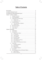
Table of Contents Box Contents...5 GA-7PESL Motherboard Layout 6 GA-7PESLX/GA-7PESLN Motherboard Layout 9 Chapter 1 Hardware Installation 12 1-1 Installation Precautions 12 1-2 Product Specifications 13 1-3 Installing the CPU and CPU Cooler 15 1-3-1 Installing the CPU...15 1-3-2 Installing the - Gigabyte GA-7PESL | Manual - Page 4
2-5-3 System Event Log 80 2-6 Boot Option Menu 81 2-7 Boot Manager 83 2-8 Exit Menu...84 - 4 - - Gigabyte GA-7PESL | Manual - Page 5
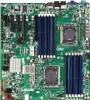
Box Contents Motherboard Driver CD Two SATA cables I/O Shield • The box contents above are for reference only and the actual items shall depend on the product package you obtain. The box contents are subject to change without notice. • The motherboard image is for reference only. - 5 - - Gigabyte GA-7PESL | Manual - Page 6
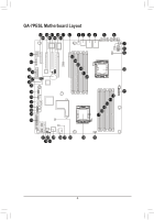
GA-7PESL Motherboard Layout 43 45 47 49 51 52 1 2 3 4 5 6 44 46 48 50 42 41 40 39 38 37 36 35 7 8 9 53 54 55 56 10 57 58 34 11 33 12 32 13 14 31 15 30 16 29 17 28 27 25 23 22 21 20 26 24 19 18 - 6 - - Gigabyte GA-7PESL | Manual - Page 7
CPU) SATA SGPIO connector System fan connector 8 pin power connector System fan connector BIOS write protect jumper SATA3 port DOM support jumper SATA2 port DOM support jumper SATA 3Gb/s connectors 24-pin power connector System fan connector Intel C600 series Upgrade Key RAID Select connector SATA - Gigabyte GA-7PESL | Manual - Page 8
to 2-3 pins (Normal mode), in order to reduce any risk of hard disk damage. Please refer to Page 48 for SATA2_D and SATA3_D jumper setting instruction. - 8 - - Gigabyte GA-7PESL | Manual - Page 9
GA-7PESLX/GA-7PESLN Motherboard Layout 43 45 47 49 51 52 1 2 3 4 5 6 44 46 48 50 42 41 40 39 38 37 36 35 34 33 32 31 30 28 28 7 8 9 53 54 55 56 10 57 58 11 12 13 14 15 16 17 18 27 26 25 24 22 21 20 19 23 - 9 - - Gigabyte GA-7PESL | Manual - Page 10
COM2 Description ID switch BMC Management LAN port (GA-7PESL/GA-7PESLX) LAN1 port (top) / USB ports ( GA-7PESLX only) Mini SAS connector Mini SAS connector (SATA signal/GA-7PESLN) SATA SGPIO connector SATA 3Gb/s connectors SATA 6Gb/s connectors SATA3 port DOM support jumper SATA2 port DOM support - Gigabyte GA-7PESL | Manual - Page 11
to 2-3 pins (Normal mode), in order to reduce any risk of hard disk damage. Please refer to Page 48 for SATA2_D and SATA3_D jumper setting instruction. - 11 - - Gigabyte GA-7PESL | Manual - Page 12
electrostatic discharge (ESD). Prior to installation, carefully read the user's manual and follow these procedures: • Prior to installation, do not remove are uncertain about any installation steps or have a problem related to the use of the product, please consult a certified computer technician. - Gigabyte GA-7PESL | Manual - Page 13
x PCI Express x8 slot, running at x4 (Gen3/PCIE_4/GA-7PESLX/GA-7PESLN) 1 x PCI Express x4 slot, running at x1 (Gen2/PCIE_5) ASPEED® AST2300 supports 128MB VRAM (GA-7PESL/GA-7PESLX) ASPEED® AST1300 supports 128MB VRAM (GA-7PESLN) Intel® C600 controller 2 x SATA 6Gb/s connectors (SATA0/1) 4 x SATA 3Gb - Gigabyte GA-7PESL | Manual - Page 14
is supported will depend on the CPU/system cooler you install. ŠŠ 1 x 64 Mbit flash ŠŠ AMI BIOS ŠŠ GA-7PESL: EEB Form Factor; 12 inch x 13 inch, 6 layers PCB ŠŠ GA-7PESLX: EEB Form Factor; 12 inch x 13 inch, 8 layers PCB ŠŠ GA-7PESLN: EEB Form Factor; 12 inch x 13 inch, 8 layers PCB * GIGABYTE - Gigabyte GA-7PESL | Manual - Page 15
and CPU Cooler Read the following guidelines before you begin to install the CPU: • Make sure that the motherboard supports the CPU. (Go to GIGABYTE's website for the latest CPU support list.) • Always turn off the computer and unplug the power cord from the power outlet before installing the CPU - Gigabyte GA-7PESL | Manual - Page 16
1-3-2 Installing the CPU Cooler Follow the steps below to correctly install the CPU cooler on the motherboard. Step 1. Attach the heat sink clip to the processor socket. Step 2. Secure the cooing fan with screws.. Step 3. Connect processor fan can cable to the processor fan connector. 1 1 1 1 2 Use - Gigabyte GA-7PESL | Manual - Page 17
the same capacity, brand, speed, and chips be used. (Go to GIGABYTE's website for the latest supported memory speeds and memory modules.) • Always turn off the computer and unplug DDR3_P1_D0 DDR3_P1_D1 DDR3_P1_E0 DDR3_P1_E1 DDR3_P1_F0 DDR3_P1_F1 GA-7PESL Channel 1 Channel 2 Channel 3 DDR3_P0_A0 - Gigabyte GA-7PESL | Manual - Page 18
1-4-2 Installing a Memory Before installing a memory module, make sure to turn off the computer and unplug the power cord from the power outlet to prevent damage to the memory module. Be sure to install DDR3 DIMMs on this motherboard. Installation Step: Step 1. Insert the DIMM memory module - Gigabyte GA-7PESL | Manual - Page 19
the states of the LAN port LEDs. KVM Server Management 10/100 LAN Port (GA-7PESL/GA-7PESLX) The LAN port provides Internet connection with data transfer speeds of 10/100Mbps. USB 2.0/1.1 Port The USB port supports the USB 2.0/1.1 specification. Use this port for USB devices such as a USB keyboard - Gigabyte GA-7PESL | Manual - Page 20
Speed LED Link Activity LED 10/100 LAN Port MLAN Speed LED: Link/Activity LED: State Green On Green Blink Off Description 100 Mbps data rate 10 Mbps or 100 Mbps data rate 10 Mbps data rate State Description On Link between system and network or no access Blinking Data transmission or - Gigabyte GA-7PESL | Manual - Page 21
1-6 Internal Connectors GA-7PESL 21 18 24 17 16 20 15 14 10 3 6 13 4 12 2223 9 1 11 8 2 19 5 7 1) ATX1 2) P12V_AUX1 3) P12V_AUX2 4) PMBUS_CN_1 5) CPU0_FAN (for primary CPU) 6) CPU1_FAN (for seconary - Gigabyte GA-7PESL | Manual - Page 22
GA-7PESLX/GA-7PESLN 21 18 24 17 16 20 15 14 10 3 6 12 11 1 19 4 13 23 22 9 8 1) 2) 3) Fan) SYS_FAN2 (System Fan) SYS_FAN4 (System Fan) SYS_FAN3 (System Fan) SATA2/3/4/5 SATA0/1 MIN_CN1/ MINII_CN2 (GA-7PESLX only) 2 7 5 14) F_USB1 15) F_USB2 16) COM2 17) TPM_MEZZ1 18) IPMB 19) SATA_SGPIO - Gigabyte GA-7PESL | Manual - Page 23
Read the following guidelines before connecting external devices: • First make sure your devices are compliant with the connectors you wish to connect. • Before installing the devices, be sure to turn off the devices and your computer. Unplug the power cord from the power outlet to prevent damage to - Gigabyte GA-7PESL | Manual - Page 24
, the result can lead to an unstable or unbootable system. P12V_AUX1 (GA-7PEXSL) 51 P12V_AUX1 (GA-7PEXSLX) (GA-7PESLN) 48 GA-7PESL 84 P12V_AUX2 (GA-7PEXSL) 48 15 P12V_AUX1 (GA-7PEXSLX) (GA-7PESLN) 51 GA-7PESLX GA-7PESLN 15 84 Pin No. 1 2 3 4 5 6 7 8 Definition GND GND GND GND +12V +12V - Gigabyte GA-7PESL | Manual - Page 25
15 16 17 18 19 20 21 22 23 24 Definition 3.3V -12V GND PS_ON GND GND GND -5V +5V +5V +5V GND ATAXT_X12_V12V FDFDDD GA-7PESL Pin No. Definition 1 1 SMB CLK 2 SMB DATA 3 SMB Alert 5 4 GND 5 3.3V Sense GA-7PESLX GA-7PESLN IDEIDE Hardware Installation - 25 - - Gigabyte GA-7PESL | Manual - Page 26
SYS_FAN2 SYS_FAN4 SYS_FAN3 CPU1_FAN GA-7PESL 1 CPU0_FAN 1 CPU1_FAN 1 1 SYS_FAN1 (GA-7PEXSL) 1 SYS_FAN2 SYS_FAN4 (GA-7PESL) SYS_FAN3 (GA-7PESL) 1 CPU0_FAN SYS_FAN3 CPU1_FAN SYS_FAN1 SYS_FAN2 SYS_FAN3 SYS_FAN4 (GA-7PESLX) (GA-7PESLN) GA-7PESLX GA-7PESLN Pin No. 1 2 3 4 Definition GND - Gigabyte GA-7PESL | Manual - Page 27
to Normal Mode: GA-7PESL SATA0 SATA1 7 7 1 1 Pin No. 1 2 3 4 5 6 7 Definition GND TXP TXN GND RXN RXP GND SATA5 SATA4 SATA3 SATA2 SATA0 SATA1 When SATA_DOM1/2 Jumper are set to 1-2 pin: Pin No. Definition 1 GND 2 TXP 3 TXN 4 GND 5 RXN 6 RXP 7 P5V GA-7PESLX GA-7PESLN SATA2 SATA4 SATA3 - Gigabyte GA-7PESL | Manual - Page 28
Yes Yes Yes MINI_CN2 Yes Yes No SAS/SATA SATA SAS SATA MINI_CN1 MINI_CN2 MINI_CN1 MINI_CN2 A1 B1 GA-7PESL A18 B18 GA-7PESLX GA-7PESLN Pin No. A1 A2 A3 A4 A5 A6 A7 A8 A9 A10 A11 A12 A13 A14 A15 A16 A17 A18 Definition GND RX0+ RX0GND RX1+ - Gigabyte GA-7PESL | Manual - Page 29
USB bracket. For purchasing the optional USB bracket, please contact the local dealer. F_USB_2 F_USB_1 GA-7PESL 12 9 10 Pin No. 1 2 3 4 5 6 7 8 9 10 Definition Power (5V) Power (5V) USB DXUSB DYUSB DX+ USB DY+ GND GND No Pin NC F_USB_2 F_USB_1 GA-7PESLX GA-7PESLN Hardware Installation - 29 - - Gigabyte GA-7PESL | Manual - Page 30
can provide one serial port via an optional COM port cable. For purchasing the optional COM port cable, please contact the local dealer. GA-7PESL 12 9 10 Pin No. 1 2 3 4 5 6 7 8 9 10 Definition NDCDNSIN NSOUT NDTRGND NDSRNRTSNCTSNRI No Pin GA-7PESLX GA-7PESLN Hardware Installation - 30 - - Gigabyte GA-7PESL | Manual - Page 31
17) TPM_MEZZ1 (TPM Module Connector) GA-7PESL Pin No. Definition 12 1 CLK_33M_TPM 2 P_3V3_AUX 3 LPC_RST_DEBUG 4 P3V3 5 LPC_LAD0 13 14 6 IRQ_SERIAL 7 LPC_LAD1 8 TPM_DET_N 9 LPC_LAD2 10 NC 11 LPC_LAD3 12 GND 13 LPC_FRAME_N 14 GND GA-7PESLX GA-7PESLN Hardware Installation - 31 - - Gigabyte GA-7PESL | Manual - Page 32
18) IPMB (IPMB connector) GA-7PESL 3 Pin No. Definition 1 SCL 2 GND 1 3 SDA GA-7PESLX GA-7PESLN Hardware Installation - 32 - - Gigabyte GA-7PESL | Manual - Page 33
workstation computer that interfaces with Hard disk drives (HDDs) to store and retrieve data. GA-7PESL Pin No. Definition 87 1 SGPIO_SATA_DATAOUT1 2 No Pin 3 SGPIO_SATA_DATAOUT0 21 4 GND 5 GND 6 SGPIO_SATA_LOAD 7 NC 8 SGPIO_SATA_CLOCK GA-7PESLX GA-7PESLN Hardware Installation - 33 - - Gigabyte GA-7PESL | Manual - Page 34
chassis to this header according to the pin assignments below. Note the positive and negative pins before connecting the cables. GA-7PESL GA-7PESLX GA-7PESLN Pin No. Signal Name Definition 1 PWLED+ Power LED Signal anode (+) 2 5VSB 5V Stanndby Power 3 NC No Pin 4 ID_LED+ ID - Gigabyte GA-7PESL | Manual - Page 35
level, or the CMOS values may not be accurate or may be lost. GA-7PESL You may clear the CMOS values by removing the battery: 1. Turn off your battery. 4. Plug in the power cord and restart your computer. GA-7PESLX GA-7PESLN • Always turn off your computer and unplug the power cord before - Gigabyte GA-7PESL | Manual - Page 36
22) SKU_KEY1 (Patsburg Upgrade ROM Hearder/GA-7PESL) 3 GA-7PESL 1 Pin No. 1 2 3 Definition GND FM_PBG_DYN_SKU_KEY GND 23) RAID_KEY1 (RAID Selection Hearder/GA-7PESL) GA-7PESL 3 1 Pin No. 1 2 3 Definition GND FM_SSB_SAS_SATA_RAID_KEY GND - 36 - Hardware Installation - Gigabyte GA-7PESL | Manual - Page 37
24) BMC_LED1 (BMC Firmware Readiness LED/GA-7PESL) GA-7PESL Link/Activity: State Description On BMC firmware is initial Blinking BMC firmware is ready Off System is powered off - 37 - Hardware Installation - Gigabyte GA-7PESL | Manual - Page 38
22) RAID_KEY2 (RAID Select Hearder/GA-7PESLX Only) GA-7PESLX GA-7PESLN Pin No. 1 2 Definition GPIO GND 23) LED2 (LSI Firmware Readiness LED/GA-7PESLX Only) GA-7PESLX GA-7PESLN LED2 Link/Activity: State Description Blinking LSI firmware is ready Off LSI firmware is not ready Hardware - Gigabyte GA-7PESL | Manual - Page 39
24) BMC_LED1 (BMC Firmware Readiness LED/GA-7PESLX Only) GA-7PESLX GA-7PESLN Link/Activity: State Description On BMC firmware is initial Blinking BMC firmware is ready Off System is powered off Hardware Installation - 39 - - Gigabyte GA-7PESL | Manual - Page 40
1-7 Jumper Setting GA-7PESL 1 6 45 3 78 2 1) CLR_CMOS 2) BIOS_WP 3) SSB_ME1 4) ROMST_FRB3 (GA-7PESLX Only) 5) BIOS_RCVR 6) PASSSWORD 7) SATA2_D 8) SATA3_D - 40 - Hardware Installation - Gigabyte GA-7PESL | Manual - Page 41
GA-7PESLX/GA-7PESLN 1 6 45 38 7 2 1) CLR_CMOS 2) BIOS_WP 3) SSB_ME1 4) ROMST_FRB3 5) BIOS_RCVR 6) PASSSWORD 7) SATA2_D 8) SATA3_D - 41 - Hardware Installation - Gigabyte GA-7PESL | Manual - Page 42
Normal operation (Default setting) 2-3 Close: Clear CMOS data. 1 GA-7PESL GA-7PESLX GA-7PESLN • Always turn off your computer and unplug the power cord from factory defaults (select Load Default Values) or manually configure the BIOS settings (refer to Chapter 2, "BIOS Setup," for - Gigabyte GA-7PESL | Manual - Page 43
Jumper) GA-7PESL 1 1-2 Close: Normal operation. (Default setting) GA-7PESL 1 2-3 Close: Enable BIOS write protect function. GA-7PESLX/GA-7PESLN 1 1-2 Close: Normal operation. (Default setting) 1 2-3 Close: Enable BIOS write protect function. GA-7PESLX GA-7PESLN Hardware Installation - Gigabyte GA-7PESL | Manual - Page 44
3) SSB_ME1 (ME enable/disable Jumper) 1-2 Close: Disable ME function. 1 GA-7PESL 1 2-3 Close: Normal operation. (Default setting) GA-7PESLX GA-7PESLN - 44 - Hardware Installation - Gigabyte GA-7PESL | Manual - Page 45
4) RMOST_FRB3 (Force to Stop FRB3 Timer Jumper/GA-7PESL/GA-7PESLX) GA-7PESL 1 1-2 Close: Normal operation. (Default setting) 1 2-3 Close: Force to Stop FRB3 Timer GA-7PESLX GA-7PESLN - 45 - Hardware Installation - Gigabyte GA-7PESL | Manual - Page 46
5) BIOS_RVCR (BIOS Recovery Jumper) GA-7PESL 1-2 Close: Normal operation. (Default setting) 1 2-3 Close: BIOS recovery mode. 1 GA-7PESLX GA-7PESLN Hardware Installation - 46 - - Gigabyte GA-7PESL | Manual - Page 47
6) PASSWORD (Skip Supervisor Password Jumper) GA-7PESL 1-2 Close: Normal operation. (Default setting) 1 2-3 Close: Skip supervisor password. 1 GA-7PESLX GA-7PESLN Hardware Installation - 47 - - Gigabyte GA-7PESL | Manual - Page 48
jumper is closed and set to 2-3 pins (Normal mode), in order to reduce any risk of hard disk damage. 1 1-2 Close: Enable SATA0/SATA1 port DOM support. 1 GA-7PESL 2-3 Close: Normal mode. (Default setting) GA-7PESLX GA-7PESLN - 48 - Hardware Installation - Gigabyte GA-7PESL | Manual - Page 49
Setup program, press the key during the POST when the power is turned on. • BIOS flashing is potentially risky, if you do not encounter problems of using the current BIOS version, it is recommended that you don't flash the BIOS. To flash the BIOS, do it with caution. Inadequate BIOS - Gigabyte GA-7PESL | Manual - Page 50
changes in BIOS Setup. A user password only allows you to view the BIOS settings but not to make changes. Server Management (GA-7PESL/GA-7PESLX) Server additional features enabled/disabled setup menus. Boot Options This setup page provides items for configuration of boot sequence. Boot Manager - Gigabyte GA-7PESL | Manual - Page 51
2-1 The Main Menu Once you enter the BIOS Setup program, the Main Menu (as shown below) appears on the screen. Use arrow keys to move among the items and press to accept or enter other sub-menu. Main Menu Help The on-screen description of a highlighted setup option is displayed on the bottom - Gigabyte GA-7PESL | Manual - Page 52
BIOS Information BIOS Version Display version number of the BIOS setup utility. Memory Information Total Memory Determines how much total memory is present during the POST. System Date Set the date following the weekday-month-day- year format. System Time Set the system time following the hour- - Gigabyte GA-7PESL | Manual - Page 53
2-2 Advanced Menu The Advanced menu display submenu options for configuring the function of various hardware components. Select a submenu item, then press Enter to access the related submenu screen. GA-7PESL/GA-7PESLX - 53 - BIOS Setup - Gigabyte GA-7PESL | Manual - Page 54
GA-7PESLN - 54 - BIOS Setup - Gigabyte GA-7PESL | Manual - Page 55
2-2-1 H/W Monitor (GA-7PESLN) Press Enter to view the Hardware Monitor screen which displays a real-time record of the CPU/system temperature, fan speed, and voltage. Items on this window are non-configurable. - 55 - BIOS Setup - Gigabyte GA-7PESL | Manual - Page 56
2-2-2 PCI Configuration PCI Express Slot 1/2/3/4/5 I/O ROM When enabled, This setting will initialize the device expansion ROM for the related PCI-E slot. Options available: Enabled/Disabled. Default setting is Enabled. Onboard LAN1/2 Controller Enable/Disable Onboard LAN controller . Options - Gigabyte GA-7PESL | Manual - Page 57
2-2-3 Trusted Computing TPM Support Select Enabled to activate TPM support feature. Options available: Enabled/Disabled. Default setting is Enabled. TPM State (Note) Select Enabled to activate TPM State function. Options available: Enabled/Disabled. Default setting - Gigabyte GA-7PESL | Manual - Page 58
2-2-4 CPU Configuration BIOS Setup - 58 - - Gigabyte GA-7PESL | Manual - Page 59
the information of the processor core. Intel HT Technology Display Intel Hyper Threading Technology function support information. Intel VT-x Technology Display Intel Virtualization Technology function support information. Cache Information L1 Data Cache Display the information of L1 Data Cache. L1 - Gigabyte GA-7PESL | Manual - Page 60
CPU Speed Display the current installed CPU speed. 64-bit Display the supported infprmation of installed CPU. Hyper-threading The Intel Hyper Threading Technology allows . Note: This register will be changed by OS too if OS support it like Windows 2008 or newer Linux. Options available: Performance : - Gigabyte GA-7PESL | Manual - Page 61
EIST (Enhanced Intel SpeedStep Technology) Conventional Intel SpeedStep Technology switches both voltage and frequency in tandem between high and low levels in response to processor load. Options available: Enabled/Disabled. Default setting is Enabled. Turbo Mode When this feature is enabled, the - Gigabyte GA-7PESL | Manual - Page 62
2-2-5 Runtime Error Logging Runtime Error Logging Support Enable/Disable Runtime error logging support. Options available: Enabled/Disabled. Default setting is Disabled. - 62 - BIOS Setup - Gigabyte GA-7PESL | Manual - Page 63
2-2-6 SATA Configuration SATA Port 0/1/2/3/4/5 (Note) Displays the installed HDD devices information. SATA Mode Select the on chip SATA type. IDE Mode: When set to IDE, the SATA controller disables its RAID and AHCI functions and runs in the IDE emulation mode. This is not allowed to access RAID - Gigabyte GA-7PESL | Manual - Page 64
2-2-7 SAS Configuration (GA-7PESLX) SAS Configuration (Note) Device 0/1/2/3 Displays the installed HDD devices information. (Note) This item only applied for GA-7PESLX. - 64 - BIOS Setup - Gigabyte GA-7PESL | Manual - Page 65
2-2-8 Super IO Configuration BIOS Setup - 65 - - Gigabyte GA-7PESL | Manual - Page 66
Serial Port 1/2 Configuration Serial Port Configuration When enabled allows you to configure the serial port settings. When set to Disabled, displays no configuration for the serial port. Options available: Enabled/Disabled. Default setting is Enabled. Device Settings Displays the Serial Port - Gigabyte GA-7PESL | Manual - Page 67
2-2-9 Serial Port Console Redirection (GA-7PESLN) Console Redirection (Note) Select whether to enable console redirection for specified device. Console redirection enables users to manage the system from a remote location. Options available: - Gigabyte GA-7PESL | Manual - Page 68
flow control uses two wires to send start/stop signals. Options available: None/Hardware RTS/CTS. VT-UTF8 Combo Key Support Enable/Disable VT-UTF8 Combo Key Support. Options available: Enabled/Disabled. Default setting is Enabled. Recorder Mode When this mode enabled, only text will be send. This - Gigabyte GA-7PESL | Manual - Page 69
2-3 Chipset Menu The Chipset menu display submenu options for configuring the function of North Bridge and South Bridge. Select a submenu item, then press Enter to access the related submenu screen. BIOS Setup - 69 - - Gigabyte GA-7PESL | Manual - Page 70
2-3-1 North Bridge Configuration Compatibility RID Enable/Disable Compatibility RID function. Options available: Enabled/Disabled. Default setting is Enabled. Memory Configuration Total Memory Determines how much total memory is present during the POST. Current Memory Mode Displays the cuurent - Gigabyte GA-7PESL | Manual - Page 71
DIMM Voltage Configure the DIMM voltage. Options available: Auto/ Force 1.5v/Force 1.35v. Default setting is Auto. Enforce DIMM To enforce POR function. When disabled, the system will enforce 1600MHz LRDIMM. Options available: Enforce EN/Stretch EN/Enforce DIS. Default setting is Enforce EN. To - Gigabyte GA-7PESL | Manual - Page 72
2-3-1-1 IOH Configuration - 72 - BIOS Setup - Gigabyte GA-7PESL | Manual - Page 73
the information of Target VGA. Options available: Onboard/Offboard. Default setting is Offboard. Gen3 Equalization WA's Enable/DIsable the support for Gen3 Equalization Workaround. Options available: Enabled/Disabled. Default setting is Disabled. Intel(R) VT-d Enable/Disable Intel VT-d Technology - Gigabyte GA-7PESL | Manual - Page 74
2-3-1-2 DIMM Information DIMM Information: DIMM Group: CPU Socket 0/1 DIMM Information CPU Socket 0: DDR3_P0_A0/DDR3_P0_A1/DDR3_P0_B0/DDR3_P0_B1/DDR3_P0_C0/DDR3_P0_C1 Status The size of memory installed on each of the DDR3 slots. CPU Socket 1: DDR3_P0_E0/DDR3_P0_E1/DDR3_P0_F0/DDR3_P0_F1/DDR3_P0_F0/ - Gigabyte GA-7PESL | Manual - Page 75
Displays the name and stepping information of the south bridge. SB Chipset Configuration PCH Compatibility RID Enable/Disable PCH Compatibility RID support. Options available: Enabled/Disabled. Default setting is Disabled. Restore on AC Power Loss (Note) Defines the power state to resume to - Gigabyte GA-7PESL | Manual - Page 76
2-4 Security Menu The Security menu allows you to safeguard and protect the system from unauthorized use by setting up access passwords. There are two types of passwords that you can set: • Administrator Password Entering this password will allow the user to access and change all settings in the - Gigabyte GA-7PESL | Manual - Page 77
2-5 Server Management Menu (GA-7PEXL/GA-7PESLX) System Information Displays basic system ID information, as well as BIOS version. Press Enter to access the related submenu. BMC LAN Configuration BMC LAN Configuration. - Gigabyte GA-7PESL | Manual - Page 78
2-5-1 System Information The System Management submenu is a simple display page for basic system ID information, as well as System product information. Items on this window are non-configurable. BIOS Setup - 78 - - Gigabyte GA-7PESL | Manual - Page 79
2-5-2 BMC LAN Configuration Configuration Source Select to configure LAN channel parameters statically or dynamically (DHCP). Do nothing option will not modify any BMC network parameters during BIOS phase. Options available: Static/Dynamic/Do Nothing. IP Address Display IP Address information. - Gigabyte GA-7PESL | Manual - Page 80
2-5-3 System Event Log SEL Components Enable/Disable all features fo system event logging during system boot. Options available: Enabled/Disabled. Erase SEL Choose this option for erasing Smbios Event Log is done prior to any logging activation during reset. BIOS Setup - 80 - - Gigabyte GA-7PESL | Manual - Page 81
2-6 Boot Option Menu The Boot menu allows you to set the drive priority during system boot-up. BIOS setup will display an error message if the legacy drive(s) specified is not bootable. Boot Priority Order Boot Option Press Enter to configure the boot priority. By default, the server searches for - Gigabyte GA-7PESL | Manual - Page 82
Interrupt 19 Capture Interrupt 19 is the software interrupt that handles the boot disk function. When enabled, this BIOS feature allows the ROM BIOS of those host adaptors to "capture" Interrupt 19 during the boot process so that drives attached to these adaptors can function as bootable disks. - Gigabyte GA-7PESL | Manual - Page 83
2-7 Boot Manager The Boot manager menu allows you to specify the boot-up drive. BIOS setup will display an error message if the legacy drive(s) specified is not bootable. Boot Override UEFI: Built-in EFI Shell Press Enter to configure the device as the boot-up drive. - 83 - BIOS Setup - Gigabyte GA-7PESL | Manual - Page 84
2-8 Exit Menu The Exit menu displays the various options to quit from the BIOS setup. Highlight any of the exit options then press Enter. Save Changes and Exit Saves changes made and close the BIOS setup. Options available: Yes/No. Discard Changes and Exit Discards changes made and close the BIOS - Gigabyte GA-7PESL | Manual - Page 85
Options available: Yes/No. Load User Default Values Loads the user default settings for all BIOS setup parameters. Options available: Yes/No. - 85 - BIOS Setup
-
 1
1 -
 2
2 -
 3
3 -
 4
4 -
 5
5 -
 6
6 -
 7
7 -
8
-
9
-
10
-
11
-
12
-
13
-
14
-
15
-
16
-
17
-
18
-
19
-
20
-
21
-
22
-
23
-
24
-
25
-
26
-
27
-
28
-
29
-
30
-
31
-
32
-
33
-
34
-
35
-
36
-
37
-
38
-
39
-
40
-
41
-
42
-
43
-
44
-
45
-
46
-
47
-
48
-
49
-
50
-
51
-
52
-
53
-
54
-
55
-
56
-
57
-
58
-
59
-
60
-
61
-
62
-
63
-
64
-
65
-
66
-
67
-
68
-
69
-
70
-
71
-
72
-
73
-
74
-
75
-
76
-
77
-
78
-
79
-
80
-
81
-
82
-
83
-
84
-
85
 |
 |

GA-7PESL
GA-7PESLX
GA-7PESLN
Dual LGA1356 sockets motherboard for Intel
®
Xeon
series processors
User's Manual
Rev. 1001