Gigabyte GA-7S748-L User Manual
Gigabyte GA-7S748-L Manual
 |
View all Gigabyte GA-7S748-L manuals
Add to My Manuals
Save this manual to your list of manuals |
Gigabyte GA-7S748-L manual content summary:
- Gigabyte GA-7S748-L | User Manual - Page 1
finger is compatible with 2X(3.3V)/4X(1.5V) mode AGP slot, but they support 2X(3.3V) only. The GA-7S748 Series (or any AGP 4X only) motherboards might not function properly, If you install this card in it. Note : Although Gigabyte's AG32S(G) graphics card is based on ATi Rage 128 Pro chip, the - Gigabyte GA-7S748-L | User Manual - Page 2
. M Third-party brands and names are the property of their respective owners. M Please do not remove any labels on motherboard, this may void the warranty of this motherboard. M Due to rapid change in technology, some of the specifications might be out of date before publication of this booklet - Gigabyte GA-7S748-L | User Manual - Page 3
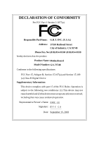
description of the apparatus, system, installation to which it refers) Mother Board GA-7S748 is in conformity with (reference to the specification under which conformity is technology equipment Cabled distribution systems; Equipment for receiving and/or distribution from sound and television - Gigabyte GA-7S748-L | User Manual - Page 4
City of Industry, CA 91748 Phone/Fax No: (818) 854-9338/ (818) 854-9339 hereby declares that the product Product Name: Motherboard Model Number:GA-7S748 Conforms to the following specifications: FCC Part 15, Subpart B, Section 15.107(a) and Section 15.109 (a),Class B Digital Device Supplementary - Gigabyte GA-7S748-L | User Manual - Page 5
GA-7S748 Series AMD Socket A Processor Motherboard USER'S MANUAL AMD Athlon™ /Athlon™ XP / Duron™ SocketA ProcessorMotherboard Rev. 1003 12ME-7S748-1003 - Gigabyte GA-7S748-L | User Manual - Page 6
16 Step 4-1: I/O Back Panel Introduction 16 Step 4-2: Connectors Introduction 18 Chapter 3 BIOS Setup 29 The Main Menu (For example: BIOS Ver. F3c 30 Standard CMOS Features 32 Advanced BIOS Features 35 Integrated Peripherals 37 Power Management Setup 41 GA-7S748 Series Motherboard - 2 - - Gigabyte GA-7S748-L | User Manual - Page 7
Exit Without Saving 52 Chapter 4 Technical Reference 55 @ BIOSTM Introduction 55 Easy TuneTM 4 Introduction 56 Flash BIOS Method Introduction 57 2-/4-/6-Channel Audio Function Introduction 61 Jack-Sensing Introduction 67 Xpress Recovery Introduction 69 Chapter 5 Appendix 73 - 3 - Table of - Gigabyte GA-7S748-L | User Manual - Page 8
cable x 1 CD for motherboard driver & utility GA-7S748 Series user's manual I/O Shield Quick PC Installation Guide RAID Manual GC-SATA Card (Optional) (M anual; SATA cable x1; Power cable x 1) 2 Port USB Cable x 1 4 Port USB Cable x 1 SPDIF-KIT x 1 (SPDIF Out KIT) IEEE 1394 Cable x1 Audio Combo Kit - Gigabyte GA-7S748-L | User Manual - Page 9
form factor, 4 layers PCB. - GA-7S748 Series Motherboard: GA-7S748 and GA-7S748-L - Socket Aprocessor AMD AthlonTM/AthlonTM XP/ DuronTM (K7) 128K L1 & 256K/64K L2 cache on die 200/266/333/400 MHz FSB and DDR bus speeds - Supports 1.4GHz and faster - SiS 748 Host/Memory controller - SiS 963L MuTIOL - Gigabyte GA-7S748-L | User Manual - Page 10
On-Board LAN (*) On-BoardSound PS/2 Connector BIOS Additional Features Overclocking - Build BIOS - Supports Q-Flash - PS/2 Keyboard power on bypassword,PS/2 Mouse power on - External Modem wake up - STR(Suspend-To-RAM Memory, Cards... .etc. (*) For GA-7S748-L only. GA-7S748 Series Motherboard - - Gigabyte GA-7S748-L | User Manual - Page 11
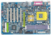
English GA-7S748 Series Motherboard Layout KB_MS USB C PU_FAN RAM_LED ATX COMA LPT GA-7S748 COMB SOC KET A U SB_LAN (*) AU DIO F_AU DIO FDD SiS 748 AGP DDR1 DDR2 DDR3 C ODEC AU X_IN CD_I N SU R_C EN RTL8201B L(* ) I T8 705 GAME BIOS SPDI F_IO PCI1 SW1 PCI2 BATTERY PCI3 PCI4 - Gigabyte GA-7S748-L | User Manual - Page 12
K7 Socket A CPU CPUCLK+/- (100/133/166/200 MHz) System Bus 266/333/400 MHz DDR SiS 748 266/333/400 MHz ZCLK (66/133MHz) HCLK+/- (100/133/166/200MHz) 66/133 MHz 33 MHz 48 MHz 14.318 MHz BIOS (66MHz) HCLK+/- (100/133/166/200MHz) (*) For GA-7S748-L only. GA-7S748 Series Motherboard - 8 - - Gigabyte GA-7S748-L | User Manual - Page 13
system Switch (SW1) Step 2- Install the Central Processing Unit (CPU) Step 3- Install memory modules Step 4- Install expansion cards Step 5- Connect ribbon cables, cabinet wires, and power supply the power outlet. Continue with the BIOS/software installation. - 9 - Hardware Installation Process - Gigabyte GA-7S748-L | User Manual - Page 14
system switch (SW1). (The internal frequencydepend on CPU.) ON SW1 1 SW1 CPU CLOCK 100MHz Auto 1 ON OFF O: ON / X :OFF Auto : Support FSB 266/333/400 MHz CPU 100MHz : Fix FSB 200M Hz CPU If you want to use a CPU with 200MHz FSB, please set SW1 to 100MHz. GA-7S748 Series Motherboard - 10 - - Gigabyte GA-7S748-L | User Manual - Page 15
English Step1-2: CPU Installation Before installing the processor, adhere to the following warning: 1.Please make sure the CPU type is supported by the motherboard. 2.If you do not match the CPU socket Pin 1 and CPU cut edge well, it will cause improper installation. Please change the insert - Gigabyte GA-7S748-L | User Manual - Page 16
. 1. Press down the CPU socket lever and finish CPU installation. 2. Use qualified fan approved byAMD. 3. Fastentheheatsinksupporting-base onto the CPUsocketon the mainboard. 4. Make sure the CPU fan is plugged to the CPU fan connector, than installcomplete. GA-7S748 Series Motherboard - 12 - - Gigabyte GA-7S748-L | User Manual - Page 17
note that the DIMM module can only fit in one direction due to the one notch. Wrong orientation will cause improper installation. Please change the insertorientation. The motherboard has 3 dual inline memory module(DIMM)sockets. The BIOS willautomatically detects memory type and size. To install the - Gigabyte GA-7S748-L | User Manual - Page 18
bandwidth of 3.2GB/s of DDR400 memory and complete line ofDDR400/333/266/200 memorysolutions,DDR memory is the bestchoice for building high performance and low latencyDRAM subsystem thatare suitable for servers, workstations, and full range of desktop PCs. GA-7S748 Series Motherboard - 14 - - Gigabyte GA-7S748-L | User Manual - Page 19
instruction documentbefore installthe expansion card into the computer. 2. Remove your computer's chassis cover, necessaryscrews and slotbracketfrom the computer. 3. Press the expansion card firmly into expansion slotin motherboard BIOS utility of expansion card from BIOS. 8. Install related driver - Gigabyte GA-7S748-L | User Manual - Page 20
PS/2 mouse. PS/2 Keyboard Connector (6pin Female) v/x USB / LAN Connector USB 3 USB 2 LAN (*) USB 1 USB 0 Before you connect your device(s) into USB or driver upgrade.Formoreinformation pleasecontactyour OS or device(s) vendors. (*) For GA-7S748-L only. GA-7S748 Series Motherboard - 16 - Gigabyte GA-7S748-L | User Manual - Page 21
(COMA / COMB) Parallel Port (25 pin Female) This connector supports 2 standard COM ports and 1 Parallel port. Device like printer pin Male) y Audio Connectors Line In(Rear Speaker) Line Out(FrontSpeaker) MIC In(Center and Subwoofer) After install onboard audio driver, you may connectspeaker to - Gigabyte GA-7S748-L | User Manual - Page 22
5) FDD 6) RAM_LED 7) PWR_LED 8) BATTERY 9) F_PANEL 5 8 16 14 2 4 15 7 9 17 10) F_AUDIO 11) SUR_CEN 12) CD_IN 13) AUX_IN 14) SPDIF_IO 15) F_USB 16) GAME 17) CLR_PWD GA-7S748 Series Motherboard - 18 - - Gigabyte GA-7S748-L | User Manual - Page 23
of the CPU cooler is essential to prevent the CPU from running under abnormal condition or damaged by overheating.The CPU fan connector supports Max. current up to 600 mA. PinNo. Definition 1 1 GND 2 +12V 3 Sense 2) SYS_FAN (System FAN Connector) This connector allows you to link with the - Gigabyte GA-7S748-L | User Manual - Page 24
IDE1 and connect CDROM to IDE2. The red stripe of the ribbon cable must be the same side with the Pin1. 39 1 IDE1 IDE2 40 2 GA-7S748 Series Motherboard - 20 - - Gigabyte GA-7S748-L | User Manual - Page 25
connect the floppy drive ribbon cables to FDD. It supports 360K,720K,1.2M,1.44M and 2.88Mbytes floppy disk types. The red stripe of the ribbon cable m ust be the same side with the Pin 1. 34 33 2 1 6) RAM_LED Do not rem ove memory modules while RAM LED is on. It might cause short or - Gigabyte GA-7S748-L | User Manual - Page 26
. If you use dual color LED, power LED will turn to another color. PinNo. Definition 1 1 MPD+ 2 MPD- 3 MPD- 8) BATTERY GA-7S748 Series Motherboard + CAUTION v Danger of explosion ifbattery is incorrectly replaced. v Replace only with the same or equivalent type recommendedbythe manufacturer - Gigabyte GA-7S748-L | User Manual - Page 27
English 9) F_PANEL (2x10 pins connector) Please connect the power LED, PC peaker, reset switch and power switch etc of your chassis front panel to the F_PANEL connector according to the pin assignm ent above. Me ssa g e LED/Po we r / Sle ep L ED So ft Pow er Co nnector Spea ker Conne ctor - Gigabyte GA-7S748-L | User Manual - Page 28
you are buying support front audio connector, please contact your dealer.Please note, you can have the alternative of using front audio connector or of using rear audio connector to play sound. 10 9 6 Definition SUROUT L SUROUTR GND NoPin CENTER_OUT BASS_OUT GA-7S748 Series Motherboard - 24 - - Gigabyte GA-7S748-L | User Manual - Page 29
12) CD_IN (CD IN Connector) Connect CD-ROM or DVD-ROM audio out to the connector. PinNo. Definition 1 1 CD-L 2 GND 3 GND 4 CD_R 13) AUX_IN (AUX In Connector) Connect other device(such as PCI TV Tunner audio out)to the connector. PinNo. Definition 1 1 AUX-L 2 GND 3 GND 4 AUX_R - 25 - Gigabyte GA-7S748-L | User Manual - Page 30
In/Out) The SPDIF output is capable of providing digital audio to external speakers or com pressed AC3 data to an unable to work or even dam age it. For optional F_USB cable, please contact your local dealer. GA-7S748 Series Motherboard 2 10 19 Pin No. 1 2 3 4 5 6 7 8 9 10 Definition Power Power - Gigabyte GA-7S748-L | User Manual - Page 31
English 16) GAME (Game Connector) This connector supports joystick, MIDI keyboard and other relate audio devices. Pin No. Definition 1 VCC 2 GRX1_R 3 GND 4 GPSA2 5 VCC 2 6 GPX2_R 16 7 GPY2_R 8 MSI_R 1 15 9 GPSA1 10 GND 11 GPY1_R 12 VCC 13 GPSB1 14 MSO_R - Gigabyte GA-7S748-L | User Manual - Page 32
English GA-7S748 Series Motherboard - 28 - - Gigabyte GA-7S748-L | User Manual - Page 33
RAM so that it retains the Setup information when the power is turned off. ENTERING SETUP Powering ON the computer and pressing immediately will allow you to enterSetup. If you require more advanced BIOS settings, please go to "Advanced BIOS Reserv ed Restore the previous CMOS value - Gigabyte GA-7S748-L | User Manual - Page 34
Window press . The Main Menu (For example: BIOS Ver. F3c) Once you enterAward BIOS Q-Flash F10:Sav e & Ex it Setup Time, Date, Hard Disk Ty pe... Figure 1: BIOS. l Advanced BIOS Features This setup page includes all the items of Award special enhanced features. GA-7S748 Series Motherboard - Gigabyte GA-7S748-L | User Manual - Page 35
system. l Save & Exit Setup Save CMOS value settings to CMOS and exit setup. l Exit Without Saving Abandon all CMOS value changes and exit setup. - 31 - BIOS Setup - Gigabyte GA-7S748-L | User Manual - Page 36
y ) Time (hh: B Floppy 3 Mode Support Halt On Base Memory Ex tended Memory Total Memory 1.44M, 3.5 in BIOS and is display only Month The month, Jan. Through Dec. Day The day , from 1 to 31 (or the max imum allow ed in the month) Year The y ear, from 1999 through 2098 GA-7S748 Series Motherboard - Gigabyte GA-7S748-L | User Manual - Page 37
time is calculated base on the 24-hour militarytime clock. For example, 1 p.m. is 13:00:00. IDE Primary Master, Slave / IDE Secondary Master, Slave The category identifies the types of hard disk from driveC to F that has been installed in the computer. There are two types: auto type, and manual - Gigabyte GA-7S748-L | User Manual - Page 38
Support motherboard, or 640 K for systems with 640 K or more memory installed on the motherboard. Extended Memory The BIOS determines how much extended memory is present during the POST. This is the amount of memory located above 1 MB in the CPU's memory address map. GA-7S748 Series Motherboard - Gigabyte GA-7S748-L | User Manual - Page 39
F10:Sav e ESC:Ex it F1:General Help F5:Prev ious Values F6:Fail-Safe Defaults F7:Optimized Defaults Figure 3: Adv anced BIOS Features First / S econd / Third Boot Device by USB-HDD. LAN Select y our boot dev ice priority by LAN. Disabled Select y our boot dev ice priority by Disabled. - 35 - Gigabyte GA-7S748-L | User Manual - Page 40
40 tracks 720 K, 1.2 M and 1.44 M are all 80 tracks. Enabled BIOS searches for floppy disk driv e to determine it is 40 or 80 tracks. Note that BIOS can not tell from 720 K, 1.2 M or 1.44 M driv e ty pe . (Default v alue) PCI Set Init Display First to PCI. GA-7S748 Series Motherboard - 36 - - Gigabyte GA-7S748-L | User Manual - Page 41
AC97 Audio [Enabled] cable ty pe Onboard LAN Dev ice (*) [Enabled] USB Controller [Enabled] [ATA66/100/133] USB Legacy Support [Disabled Help F5:Prev ious Values F6:Fail-Safe Defaults F7:Optimized Defaults Figure 4: Integrated Peripherals (*) For GA-7S748-L only. - 37 - BIOS Setup - Gigabyte GA-7S748-L | User Manual - Page 42
detected by BIOS. (Default Audio Enabled Disabled Enable onboard AC'97 audio function. (Default v alue) Disable this function. On Board LAN Device (*) Disabled Disable this function. Enabled Enable Onboard Lan Chip dev ice. (Default Value) (*) For GA-7S748-L only. GA-7S748 Series Motherboard - Gigabyte GA-7S748-L | User Manual - Page 43
or mouse is installed, please set at Enabled. Enabled Enabled USB key board or mouse support. Disabled Disabled USB key board or mouse support. (Default v alue) Onboard Serial Port 1 Auto BIOS w ill automatically setup the port 1 address. 3F8/IRQ4 Enable onboard Serial port 1 and address is - Gigabyte GA-7S748-L | User Manual - Page 44
to 330. (Default Value) Disabled Disable this function. Midi Port IRQ 5 Set Midi Port IRQ to 5. 10 Set Midi Port IRQ to 10. (Default Value) GA-7S748 Series Motherboard - 40 - - Gigabyte GA-7S748-L | User Manual - Page 45
Disabled] Set suspend ty pe to x Month Alarm NA Suspend to RAM under x Day (of Month) 0 ACPI OS x Time (hh:mm:ss) 0 0 0 Pow er LED in S1 state [Blinking] higf: Mov e Enter:Select +/-/PU/PD:Value F10:Sav e ESC:Ex it F1:General Help F5 BIOS Setup - Gigabyte GA-7S748-L | User Manual - Page 46
Value) Resume by Alarm You can set "Resume by Alarm" item to enabled and key in Data/time to pow er on sy stem. Disabled Disable this function. (Default Value) Enabled Enable alarm function to use dual color LED, pow er LED w ill turn to another color. GA-7S748 Series Motherboard - 42 - - Gigabyte GA-7S748-L | User Manual - Page 47
Assignment [Auto] higf: Mov e Enter:Select +/-/PU/PD:Value F10:Sav e ESC:Ex it F1:General Help F5:Prev ious Values F6:Fail-Safe Defaults F7:Optimized Defaults Figure 6: PnP/PCI Configurations PCI 4 IRQ Assignment Auto 12,14,15 Set IRQ 3,4,5,7,9,10,11,12,14,15 to PCI 3. - 43 - BIOS Setup - Gigabyte GA-7S748-L | User Manual - Page 48
Speed 0 RPM higf: Mov e Enter:Select +/-/PU/PD:Value F10:Sav e ESC:Ex it F1:General Help F5:Prev ious Values F6:Fail-Safe Defaults F7:Optimized Defaults Figure 7: PC Health Status Current Voltage (V) Vcore / Detec t CPU/Sy stem Fan speed status automatic ally . GA-7S748 Series Motherboard - 44 - - Gigabyte GA-7S748-L | User Manual - Page 49
] higf: Mov e Enter:Select +/-/PU/PD:Value F10:Sav e ESC:Ex it F1:General Help F5:Prev ious Values F6:Fail-Safe Defaults F7:Optimized Defaults Figure 8: Frequency /Voltage Control Linear Frequency Control Disabled may cause y our sy stem broken. For pow er End-User use only ! - 45 - BIOS Setup - Gigabyte GA-7S748-L | User Manual - Page 50
Set CPU Voltage Control to Normal. (Default v alue) +5% Set CPU Voltage Control to +5%. +7.5% Set CPU Voltage Control to +7.5%. +10% Set CPU Voltage Control to +10%. GA-7S748 Series Motherboard - 46 - - Gigabyte GA-7S748-L | User Manual - Page 51
ard Softw are }Standard CMOS Features Top Performance }Adv anced BIOS Features Load Fail-Safe Defaults }Integrated PeripThoepralPserformance Load Optimized Defaults Performance function. You must check whether your RAM, CPU support over clock when you set "Top Performance" to "Enabled". - 47 - Gigabyte GA-7S748-L | User Manual - Page 52
1984-2003 Aw ard Softw are }Standard CMOS Features Top Performance }Adv anced BIOS Features Load Fail-Safe Defaults }Integrated Peripherals Load Optimized Defaults }Pow er Management SLeotuapd the system parameters that allow minimum system performance. GA-7S748 Series Motherboard - 48 - - Gigabyte GA-7S748-L | User Manual - Page 53
Load Optimized Defaults CMOS Setup Utility -Copy right (C) 1984-2003 Aw ard Softw are }Standard CMOS Features Top Performance }Adv anced BIOS Features Load Fail-Safe Defaults }Integrated Peripherals Load Optimized Defaults }Pow er Management Setup Set Superv isor Passw ord }PnP/PCI - Gigabyte GA-7S748-L | User Manual - Page 54
dvance BIOS Features Menu, you will be prompted for the password every time the system is rebooted or any time you try to enter Setup Menu. If youselect "Setup" at "Password Check" inAdvance BIOS Features Menu, you will be prompted only when you try to enter Setup. GA-7S748 Series Motherboard - 50 - Gigabyte GA-7S748-L | User Manual - Page 55
English Save & Exit Setup CMOS Setup Utility -Copy right (C) 1984-2003 Aw ard Softw are }Standard CMOS Features Top Performance }Adv anced BIOS Features Load Fail-Safe Defaults }Integrated Peripherals Load Optimized Defaults }Pow er Management Setup Set Superv isor Passw ord }PnP/PCI - Gigabyte GA-7S748-L | User Manual - Page 56
(C) 1984-2003 Aw ard Softw are }Standard CMOS Features Top Performance }Adv anced BIOS Features }Integrated Peripherals Load Fail-Safe Defaults Load Optimized Defaults }Pow er Management Setup saving to RTC CMOS. Type "N" will return to Setup Utility. GA-7S748 Series Motherboard - 52 - - Gigabyte GA-7S748-L | User Manual - Page 57
- 53 - BIOS Setup English - Gigabyte GA-7S748-L | User Manual - Page 58
English GA-7S748 Series Motherboard - 54 - - Gigabyte GA-7S748-L | User Manual - Page 59
why motherboard vendors could not just do something right to save your time and effort and save you from the lousy BIOS updating work? Here it comes! Now Gigabyte announces @BIOS- the first Windows BIOS live update utility. This is a smart BIOS update software. It could help you to download the BIOS - Gigabyte GA-7S748-L | User Manual - Page 60
fully supported by EasyTune 4. Please find the products supported list in the web site. *Any "Overclocking action" is at user's risk, Gigabyte Technology will not be responsible for any damage or instability to your processor, motherboard, or any other components. GA-7S748 Series Motherboard - 56 - Gigabyte GA-7S748-L | User Manual - Page 61
during POST (Power On Self Test) it will allow you to enter AWARD BIOS CMOS SETUP, then press to enter Q-Flash utility. CMOS Setup Utility Saving ESC:Quit higf:Select Item F8: Q-Flash F10:Save & Exit Setup Time, Date, Hard Disk Type... b. Q-Flash Utility Flash Type/Size : Q-Flash - Gigabyte GA-7S748-L | User Manual - Page 62
the BIOS file. !Press Enter to Run. Are you sure to update BIOS? [Enter] to contiune Or [ESC] ot abort... !Press Enter to Run. !! COPY BIOS Completed -Pass !! Please press any key to continue Congratulation! You have completed the flashed and now can restart system. GA-7S748 Series Motherboard - Gigabyte GA-7S748-L | User Manual - Page 63
Click "OK". (3) (4) Methods and steps: I. Update BIOS through Internet a. Click "Internet Update" icon b. Click "Update New BIOS" icon c. Select @BIOSTM sever d. Select the exact model name on your motherboard e. System will automatically download and update the BIOS. - 59 - Technical Reference - Gigabyte GA-7S748-L | User Manual - Page 64
won't boot. c. In method I, if the BIOS file you need cannot be found in @BIOSTM server, please go onto Gigabyte's web site for downloading and updating it according to method II. d. Please note that any interruption during updating will cause system unbooted GA-7S748 Series Motherboard - 60 - - Gigabyte GA-7S748-L | User Manual - Page 65
1: Connect the stereo speakers or earphone to "Line Out". STEP 2 : After installation of the audio driver, you'll find an icon on the taskbar's status area. Click the audio icon "Sound Effect" from the windows tray at the bottom of the screen. Line Out STEP 3: Select "Speaker Configuration", and - Gigabyte GA-7S748-L | User Manual - Page 66
installation of the audio driver, you'll find an icon on the taskbar's status area. Click the audio icon "Sound Effect" from the windows tray at the the sound would be performed as stereo mode (2 channels output). Please select the other settings for 4 channels output. GA-7S748 Series Motherboard - - Gigabyte GA-7S748-L | User Manual - Page 67
the Center/Subwoofer channels to "MIC In". MIC In Line Out STEP 2 : After installation of the audio driver, you'll find an icon on the taskbar's status area. Click the audio icon "Sound Effect" from the windows tray at the bottom of the screen. Line In STEP 3 : Select "Speaker Configuration", and - Gigabyte GA-7S748-L | User Manual - Page 68
, Line In and MIC at the same time. "SURROUND-KIT" is included in the GIGABYTE unique "Audio Combo Kit" as picture. STEP 1 : Insert the "SURROUND-KIT" in the back of the case ,and fix it with the screw. STEP 2 : Connect the "SURROUND-KIT" to SUR_CEN on the M/B. GA-7S748 Series Motherboard - 64 - - Gigabyte GA-7S748-L | User Manual - Page 69
", the rear channels to SURROUND-KIT's REAR R/L, and the Center/Subwoofer channels to SURROUND-KIT's SUB CENTER. STEP 4 : Click the audio icon "Sound Effect" from the windows tray at the bottom of the screen. STEP 5 : Select "Speaker Configuration", and choose the "6 channel for 5.1 speakers out put - Gigabyte GA-7S748-L | User Manual - Page 70
Output Device (Optional Device) A "SPDIF output" device is available on the motherboard. Cable with rear bracket is provided and could link to the "SPDIF , and fix it with screw. 2. Connect SPDIF device to the motherboard. 3. Connect SPDIF to the SPDIF decoder. GA-7S748 Series Motherboard - 66 - - Gigabyte GA-7S748-L | User Manual - Page 71
version before to enable Jack-Sensing support for Windows 98/98SE/2000/ME. Jack-Sensing includes 2 parts: AUTO and MANUAL. Following is an example for 2 channels (Windows XP): Introduction of audio connectors You may connect CDROM, Walkman or others audio input devices to Line In jack, speakers - Gigabyte GA-7S748-L | User Manual - Page 72
English If you set wrong with the connectors, the warning message will come out as right picture. Manual setting: If the device picture shows different from what you set, please press "Manual Selection" to set. GA-7S748 Series Motherboard - 68 - - Gigabyte GA-7S748-L | User Manual - Page 73
allows you to install one O.S . 4. It must be used with IDE hard disk supporting HPA . 5. The first partition must be set as the boot partition. When the boot go to "Advanced BIOS" setting menu and set boot from CD-ROM , then save and exit the BIOS menu . Later,please insert MB driver CD into your - Gigabyte GA-7S748-L | User Manual - Page 74
. GIGABYTE Technilogy CO. , Ltd. 1. Execute Backup Utility 2. Execute Restore Utility 3. Remove Backup Image 4. Exit and Restart If you ever entered Xpress Recovery by booting from CD-ROM, you'll still be directed to BMP mode by pressing F9 in the bootup screen. GA-7S748 Series Motherboard - 70 - Gigabyte GA-7S748-L | User Manual - Page 75
English 1.Execute Backup Utility: ! Press B to Backup your System or Esc to Exit The Backup utility will scan the system automatically and back up it. The backed up data will be saved as an hidden image . 2.Execute Restore Utility: ! This program will recover your system to factory default. Press R - Gigabyte GA-7S748-L | User Manual - Page 76
English GA-7S748 Series Motherboard - 72 - - Gigabyte GA-7S748-L | User Manual - Page 77
Drivers Pictures below are shown in Windows XP Insert the driver CD-title that came with your motherboard into your CD-ROM drive, the driver CD-title will auto start and show the installation guide driver manually or switch to the to install the drivers automatically. Massage: Some device drivers - Gigabyte GA-7S748-L | User Manual - Page 78
. After install Windows Service Pack, it will show a question mark "?" in "Universal Serial Bus controller" under "Device Manager". Please remove the question mark and restart the system (System will auto-detect the right USB2.0 driver). (*) For GA-7S748-L only. GA-7S748 Series Motherboard - 74 - - Gigabyte GA-7S748-L | User Manual - Page 79
overclocking and hardware monitoring functions. n DMI Viewer Windows based utility which is used to browse the DMI/SMBIOS information of the system. n Face-Wizard New utility for adding BIOS logo. n @BIOS Gigabyte windows flash BIOS hardware acceleration that support for operating system to achieve better 3D - Gigabyte GA-7S748-L | User Manual - Page 80
English SOFTWARE INFORMATION This page list the contects of softwares and drivers in this CD title. HARDWARE INFORMATION This page lists all device you have for this motherboard. CONTACT US Please see the last page for details. GA-7S748 Series Motherboard - 76 - - Gigabyte GA-7S748-L | User Manual - Page 81
Defaults) after flashing BIOS. However, if the system instability still remains, please clear CMOS to solve the problem. Question 5: Why do I still get a weak sound after turning up the speaker to the maximum volume? Answer: Please make sure the speaker you are using is equipped with an internal - Gigabyte GA-7S748-L | User Manual - Page 82
memory failure 4 beeps Timer not operational 5 beeps Processor error 6 beeps 8042 - gate A20 failure 7 beeps Processor exception interrupt error 8 beeps Display memory short: BIOS ROM error Continuous long beeps: DRAM error Continuous short beeps: Power error GA-7S748 Series Motherboard - 78 - Gigabyte GA-7S748-L | User Manual - Page 83
trouble during boot up, please follow the troubleshooting procedures . START Turn off the power and unplug the AC power cable, then remove all of the add-on cards and cables from motherboard. Please make sure motherboard . No Insert and push the memory module vertically into the DIMM slot - Gigabyte GA-7S748-L | User Manual - Page 84
your problem, please contact with your local retailer or national distributor for help. Or, you could submit your question to the service mail via Gigabyte website technical support zone (http://www.gigabyte.com.tw). The appropriate response will be provided ASAP. GA-7S748 Series Motherboard - 80 - Gigabyte GA-7S748-L | User Manual - Page 85
Lot Number: BIOS version: O.S./A.S.: Hardware Mfs. Model name Size: Configuration CPU Memory Brand Video Card Audio Card HDD CD-ROM / DVD-ROM Modem Network AMR / CNR Keyboard Mouse Power supply Other Device Phone No.: PCB revision: Driver/Utility: Problem Description: & - 81 - Gigabyte GA-7S748-L | User Manual - Page 86
Audio Modem Riser Advanced Communications Riser Basic Input / Output System Central Processing Unit Complementary Metal Oxide Semiconductor Continuity RIMM Communication and Networking Riser Direct Memory Channel Enhanced Interrupt Request to be continued...... GA-7S748 Series Motherboard - 82 - - Gigabyte GA-7S748-L | User Manual - Page 87
Acronyms IOAPIC ISA LAN I/O LBA LED Memory Translator Hub Memory Protocol Translator Network Interface Card Operating System Original Equipment Manufacturer PCI A.G.P. Controller Power-On Self Test Peripheral Component Interconnect Rambus in-line Memory Module Special Circumstance Instructions - Gigabyte GA-7S748-L | User Manual - Page 88
English GA-7S748 Series Motherboard - 84 - - Gigabyte GA-7S748-L | User Manual - Page 89
- 85 - Memo English - Gigabyte GA-7S748-L | User Manual - Page 90
English GA-7S748 Series Motherboard - 86 - - Gigabyte GA-7S748-L | User Manual - Page 91
- 87 - Memo English - Gigabyte GA-7S748-L | User Manual - Page 92
English GA-7S748 Series Motherboard - 88 - - Gigabyte GA-7S748-L | User Manual - Page 93
- 89 - Memo English - Gigabyte GA-7S748-L | User Manual - Page 94
English GA-7S748 Series Motherboard - 90 - - Gigabyte GA-7S748-L | User Manual - Page 95
Bletchley Milton Keynes, MK1 1DR, UK, England TEL: +44-1908-362700 FAX: +44-1908-362709 Tech. Support : http://uk.giga-byte.com/TechSupport/ServiceCenter.htm Non-Tech. Support(Sales/Marketing) : http://ggts.gigabyte.com.tw/nontech.asp WEB address : http://uk.giga-byte.com - The Netherlands GIGA-BYTE - Gigabyte GA-7S748-L | User Manual - Page 96
www.gigabyte.ru - Poland Representative Office Of Giga-Byte Technology Co., Ltd. POLAND Tech. Support : http://tw.giga-byte.com/TechSupport/ServiceCenter.htm Non-Tech. Support(Sales/Marketing) : http://ggts.gigabyte.com.tw/nontech.asp WEB address : http://www.gigabyte.pl GA-7S748 Series Motherboard
-
 1
1 -
 2
2 -
 3
3 -
 4
4 -
 5
5 -
 6
6 -
 7
7 -
8
-
9
-
10
-
11
-
12
-
13
-
14
-
15
-
16
-
17
-
18
-
19
-
20
-
21
-
22
-
23
-
24
-
25
-
26
-
27
-
28
-
29
-
30
-
31
-
32
-
33
-
34
-
35
-
36
-
37
-
38
-
39
-
40
-
41
-
42
-
43
-
44
-
45
-
46
-
47
-
48
-
49
-
50
-
51
-
52
-
53
-
54
-
55
-
56
-
57
-
58
-
59
-
60
-
61
-
62
-
63
-
64
-
65
-
66
-
67
-
68
-
69
-
70
-
71
-
72
-
73
-
74
-
75
-
76
-
77
-
78
-
79
-
80
-
81
-
82
-
83
-
84
-
85
-
86
-
87
-
88
-
89
-
90
-
91
-
92
-
93
-
94
-
95
-
96
 |
 |

When you installing AGP card, please make sure the following
notice is fully understood and practiced. If your AGP card has
"AGP 4X/8X(1.5V) notch"(show below), please make sure your AGP
card is AGP 4X/8X(1.5V).
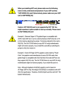
Caution: AGP 2X(3.3V) card is not supported by SiS
®
748. You
might experience system unable to boot up normally. Please insert
an AGP 4X/8X(1.5V) card
Example 1: Diamond Vipper V770 golden finger is compatible with
2X/4X mode AGP slot. It can be switched between AGP 2X(3.3V) or 4X
(1.5V) mode by adjusting the jumper. The factory default for this card is
2X(3.3V). The GA-7S748 Series (or any AGP 4X only) motherboards
might not function properly, if you install this card without switching the
jumper to 4X(1.5V) mode in it.
Example 2: Some ATi Rage 128 Pro graphics cards made by "Power
Color", the graphics card manufacturer & some SiS 305 cards, their
golden finger is compatible with 2X(3.3V)/4X(1.5V) mode AGP slot, but
they support 2X(3.3V) only. The GA-7S748 Series (or any AGP 4X only)
motherboards might not function properly, If you install this card in it.
Note : Although Gigabyte's AG32S(G) graphics card is based on
ATi Rage 128 Pro chip, the design of AG32S(G) is compliance with AGP
4X(1.5V) specification. Therefore, AG32S (G)will work fine with SiS
®
748
based motherboards.
AGP 4X/8X notch