Gigabyte GA-7VM400M User Manual
Gigabyte GA-7VM400M Manual
 |
View all Gigabyte GA-7VM400M manuals
Add to My Manuals
Save this manual to your list of manuals |
Gigabyte GA-7VM400M manual content summary:
- Gigabyte GA-7VM400M | User Manual - Page 1
/8X(1.5V). AGP 4X/8X notch Caution: AGP 2X(3.3V) card is not supported by VIA® KM400. You might experience system unable to boot up normally. Please is compatible with 2X(3.3V)/4X(1.5V) mode AGP slot, but they support 2X(3.3V) only. The GA-7VM400M(F) motherboards might not function properly, If - Gigabyte GA-7VM400M | User Manual - Page 2
M The author assumes no responsibility for any errors or omissions that may appear in this document nor does the author make a commitment to update the information contained herein. M Third-party brands and names are the property of their respective owners. M Please do not remove any labels on - Gigabyte GA-7VM400M | User Manual - Page 3
o EN 55011 o EN 55013 o EN 55014 o EN 55015 o EN 55020 T EN 55022 o DIN VDE 0855 o part 10 o part 12 Declaration of Conformity We, Manufacturer/Importer (full address) G.B.T. Technology Träding GMbH Ausschlager Weg 41, 1F, 20537 Hamburg, Germany declare that the product ( description of the - Gigabyte GA-7VM400M | User Manual - Page 4
DECLARATION OF CONFORMITY Per FCC Part 2 Section 2.1077(a) Responsible PartName: G.B.T. INC. (U.S.A.) Address: 17358 Railroad Street City of Industry, CA 91748 Phone/Fax No: (818) 854-9338/ (818) 854-9339 hereby declares that the product Product Name: Motherboard Model Number: GA-7VM400M(F) Conforms - Gigabyte GA-7VM400M | User Manual - Page 5
GA-7VM400M(F) AMD Socket A Processor Motherboard USER'S MANUAL AMD Athlon™ / Athlon™ XP / Duron™ SocketAProcessor Motherboard Rev. 1001 12ME-7VM400MF-1001 - Gigabyte GA-7VM400M | User Manual - Page 6
English Table of Content Item Checklist 4 Features Summary 5 Chapter 1 Introduction 5 GA-7VM400M(F) Motherboard Layout 7 Block Diagram 8 Chapter 2 Hardware Installation Process 10 Step 1: Install the Central Processing Unit (CPU 11 Step1-1: CPU Speed Setup 11 Step1-2: CPU Installation 12 - Gigabyte GA-7VM400M | User Manual - Page 7
English PnP/PCI Configurations 46 PC Health Status 47 Frequency/Voltage Control 49 Load Fail-Safe Defaults 51 Load Optimized Defaults 52 Set Supervisor/User Password 53 Save & Exit Setup 54 Exit Without Saving 55 Chapter 4 Technical Reference 57 @ BIOSTM Introduction 57 Easy TuneTM 4 - Gigabyte GA-7VM400M | User Manual - Page 8
The GA-7VM400MF or GA-7VM400M motherboard IDE cable x 1/ Floppy cable x 1 CD for m otherboard driver & utility GA-7VM400M(F) user's manual I/O Shield Quick PC Installation Guide RAID M anual GC-SATA Card (Optional) (M anual; SATA cable x1; Power cable x 1) 2 Port USB Cable x 1 4 Port USB Cable - Gigabyte GA-7VM400M | User Manual - Page 9
4 layers PCB. - Socket A processor AMD AthlonTM/AthlonTM XP/ DuronTM (K7) 128KL1 & 512K/256K/64K L2 cache on die 200/266/333MHz FSB and DDRbus speeds - Supports 1.4GHz and faster - VIA KM400 Memory/AGP/PCI Controller (PAC) - VIA VT8235 Integrated Peripheral Controller (PSIPC) - 2 184-pin DDR sockets - Gigabyte GA-7VM400M | User Manual - Page 10
- CD_In / Game port - Built in VIA VT8235 Chipset - RealTek RTL8100C - Ti TSB43AB23 - PS/2 Keyboard interface and PS/2 Mouse interface - Licensed Award BIOS - Supports Q-Flash - PS/2 Keyboard power on by password,PS/2 Mouse power on - External Modem wake up - STR(Suspend-To-RAM) - AC Recovery - Poly - Gigabyte GA-7VM400M | User Manual - Page 11
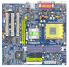
English GA-7VM400M(F) Motherboard Layout VGA USB LAN MIC_IN LINE_OUT LINE_IN KB_MS C PU_FAN RAM_LED ATX COMA LPT GA-7VM400M(F) DDR1 DDR2 FDD IDE1 SOC KETA VIA KM400 I T8705 F_AUDIO BIOS AGP 8X R TL 8 1 00 C AC 97 C D_IN SU R_C EN SPDIF_IO COMB GAME AGP PCI1 SW1 IDE2 SYS_FAN - Gigabyte GA-7VM400M | User Manual - Page 12
English Block Diagram AM D-K7TM Host CUP CPUCLK+/- (100/133/166MHz) RJ45 66MHz V_Link AGP 2X/4X/8X VGA Port 3 PCI AGPCLK 66MHz RTL8100C PCI BUS 33MHz TSB43AB23 (*) System Bus 200/266/333M Hz FSB 200/266/333MHz VIA KM 400 DDR HCLK+/- (100/133/166MHz) AGPCLK66 MHz 33 M Hz 48MHz 14.318MHz - Gigabyte GA-7VM400M | User Manual - Page 13
- 9 - Introduction English - Gigabyte GA-7VM400M | User Manual - Page 14
English Chapter 2 Hardware Installation Process To set up your compute r, you must complete the following steps: Step 1- Set system Switch (SW1) Ste p 2- Install the Central Processing Un it (CPU) Step 3- Install memory modules Step 4- Install expansion cards Step 5- Connect ribbon cables, - Gigabyte GA-7VM400M | User Manual - Page 15
to below table. O: ON / X: OFF SW1 ON 1 Default Setting: 100MHz SW1 CPU CLOCK 100 133/166 1 ON OFF 100 : Fix FSB 200MHz CPU 133/166: Support FSB 266/333MHz CPU You must set SW1 to 100MHz when you used FSB 200MHz CPU. - 11 - Hardware Installation Process - Gigabyte GA-7VM400M | User Manual - Page 16
English Step1-2: CPU Installation Before installing the processor, adhere to the following warning: 1.Please make sure the CPU type is supported by the motherboard. 2.If you do not match the CPU socket Pin 1 and CPU cut edge well, it will cause improper installation. Please change the - Gigabyte GA-7VM400M | User Manual - Page 17
this completes the installation. Please refer to CPU cooling fan user's manual for more detailinstallation procedure. 1. Press down the CPU socket lever and . 2. Use qualified fan approved by AMD. 3. Fasten the cooling fan supporting-base onto the CPU socket on the main board. 4. Make sure the - Gigabyte GA-7VM400M | User Manual - Page 18
into the DIMM Slot. The DIMM module can only fit in one direction due to the notch. Memory size can vary between sockets. Notch DDR Support Unbuffered DDR DIMM Sizes type: 64 Mbit (2Mx8x4 banks) 64 Mbit (1Mx16x4 banks) 128 Mbit(2Mx16x4 banks) 256 Mbit(8Mx8x4 banks) 512 Mbit(16Mx8x4 banks - Gigabyte GA-7VM400M | User Manual - Page 19
bandwidth. DDR SDRAM will offer a superior solution and m igration path from existing SDRAM designs due to its availability, pricing and overall market support. PC2100 DDR memory (DDR266) doubles the data rate through reading and writing at both the rising and falling edge of the clock, achieving - Gigabyte GA-7VM400M | User Manual - Page 20
English Step 3: Install expansion cards 1. Read the related expansion card's instruction document before install the expansion card into the computer. 2. Remove your computer's chassis cover,necessary screws and slotbracketfrom the computer. 3. Press the expansion card firmly - Gigabyte GA-7VM400M | User Manual - Page 21
PS/2 keyboard and PS/2 mouse. v Parallel Port, Serial Port and VGA Port (LPT/COMA/VGA) Parallel Port (25 pin Female) Ø This connector supports 1 standard COM port, 1 Parallel port and 1 VGA port. Device like printer can be connected to Parallel port ; mouse and modem e tc can be connected - Gigabyte GA-7VM400M | User Manual - Page 22
se make sure your device(s) such as USB keyboard,mouse, scanner, zip, speaker..etc. Have a standard USB interfa ce. Also make sure you r OS supports USB controller. If your OS doe s not supp ort USB con troller, please contact OS vendor for possible patch or driver upgrade. F or more information - Gigabyte GA-7VM400M | User Manual - Page 23
English Step 4-2: Connectors Introduction 1 6 10 9 12 11 1) CPU_FAN 2) SYS_FAN 3) ATX 4) IDE1/IDE2 5) FDD 6) RAM_LED 7) F_PANEL 8) PWR_LED 9) BAT 10) F_AUDIO 3 4 5 2 19 8 7 13 15 16 14 17(*) 18(*) 11) SUR_CEN 12) CD_IN 13) SPDIF_IO 14) F_USB1/F_USB2 15) COMB 16) GAME 17) F1_1394 (*) 18) - Gigabyte GA-7VM400M | User Manual - Page 24
of the CPU cooler is essential to prevent the CPU from running under abnormal condition or damaged by overheating.The CPU fan connector supports Max. current up to 600 mA. PinNo. Definition 1 1 GND 2 +12V 3 Sense 2) SYS_FAN (System FAN Connector) This connector allows you to link with the - Gigabyte GA-7VM400M | User Manual - Page 25
English 3) ATX (ATX Power) AC power cord should only be connected to your power supply unit after ATX power cable and other related devices are firmly connected to the mainboard. Pin No. Definition 1 3.3V 2 3.3V 3 GND 4 VCC 11 1 5 GND 6 VCC 7 GND 8 Power Good 9 5V SB(stand by + - Gigabyte GA-7VM400M | User Manual - Page 26
English 5) FDD (Floppy Connector) Please connect the floppy drive ribbon cables to FDD. Itsupports 360K,720K,1.2M,1.44M and 2.88Mbytes floppy disk types. The red stripe of the ribbon cable must be the same side with the Pin1. 34 33 2 1 6) RAM_LED Do not remove memory modules while RAM LED is - Gigabyte GA-7VM400M | User Manual - Page 27
English 7) F_PANEL (2x10 pins connector) Please connect the power LED, PC peaker, resetswitch and power switch etc of your chassis front panel to the F_PANEL connector according to the pin assignment above. Me ssa g e LED/Po we r / Sleep LED Soft Po wer Connector Speaker Connector MSGMSG+ 21 - Gigabyte GA-7VM400M | User Manual - Page 28
by the manufacturer. v Dispose of used batteries according to the manufacturer's instructions. If you want to erase CM OS... 1.Turn OFF the computer and on the MB header. To find out if the chassis you are buying support front audio connector, please contact your dealer.Please note, you can have - Gigabyte GA-7VM400M | User Manual - Page 29
English 11) SUR_CEN Please contact your nearest dealer for optional SUR_CEN cable. 12 56 Pin No. 1 2 3 4 5 6 Definition SUROUT L SUROUT R GND No Pin CENTER_OUT BASS_OUT 12) CD_IN (CD IN, Black) Connect CD-ROM or DVD-ROM audio out to the connector. PinNo. Definition 1 1 CD-L 2 GND 3 GND 4 - Gigabyte GA-7VM400M | User Manual - Page 30
English 13) SPDIF_IO (SPDIF In/Out) The SPDIF output is capable of providing digital audio to external speakers or compressed AC3 data to an external Dolby Digital Decoder. Use this feature only when your stereo system has digital input function. Use SPDIF IN feature only when your device has - Gigabyte GA-7VM400M | User Manual - Page 31
10 19 Pin No. 1 2 3 4 5 6 7 8 9 10 Definition NDCDBNSINB NSOUTB NDT RBGND NDSRBNRTSBNCTSBNRIBNo Pin 16) GAME (GAME Connector) This connector supports joystick, MIDI keyboard and other relate audio devices. Pin No. Definition 1 VCC 2 GRX1_R 3 GND 4 GPSA2 5 VCC 2 16 6 7 GPX2_R GPY2_R - Gigabyte GA-7VM400M | User Manual - Page 32
English 17) F1_1394 (IEEE 1394 Connector) (*) Please Note: Serial interface standard set by Institute of Electrical and Electronics Engineers, which has features like high speed, high bandwidth and hot plug. Be careful with the polarity of the IEEE1394 connector. Check the pin assignment carefully - Gigabyte GA-7VM400M | User Manual - Page 33
English 19) CI (CASE OPEN) This 2 pin connector allows your system to enable or disable the "case open" item in BIOS if the system casebegin remove. PinNo. Definition 1 1 Signal 2 GND - 29 - Hardware Installation Process - Gigabyte GA-7VM400M | User Manual - Page 34
English GA-7VM 400M (F) M otherboard - 30 - - Gigabyte GA-7VM400M | User Manual - Page 35
English Chapter 3 BIOS Setup BIOS Setup is an overview of the BIOS Setup Program. The program that allows users to modify the basic system configuration. This type of information is stored in battery-backed CMOS RAM so that it retains the Setup information when the power is turned off. ENTERING S - Gigabyte GA-7VM400M | User Manual - Page 36
English GETTING HELP Mai n Menu The on-line description of the highlighted setup function is displayed at the bottom of the screen. Status Page Setup Menu / Option Pag e S etup Menu Press F1 to pop up a small help window that describes the appropriate keys to use and the possible selections for the - Gigabyte GA-7VM400M | User Manual - Page 37
English l Integrated Peripherals This setup page includes all onboard peripherals. l Power Manag ement Setup This setup page includes all the items of Green function features. l PnP/PCI Configurations This setup page includes all the configurations of PCI & PnP ISA resources. l PC Health Status - Gigabyte GA-7VM400M | User Manual - Page 38
y ear }IDE Primary Slav e [None] }IDE Secondary Master [None] }IDE Secondary Slav e [None] Sun. to Sat. Driv e A Driv e B Floppy 3 Mode Support Halt On Base Memory Ex tended Memory Total Memory [1.44M, 3.5 in.] [None] [Disabled] [All, But Key board] 640K 130048K 131072K Jan - Gigabyte GA-7VM400M | User Manual - Page 39
identifies the types of hard disk from drive C to F that has been installed in the computer. There are two types: auto type, and manual type. Manual type is user-definable; Auto type which will automatically detect HDD type. Note thatthe specifications of your drive must match with the drive - Gigabyte GA-7VM400M | User Manual - Page 40
English Floppy 3 Mode Support (for J apan Area) Disabled Normal Floppy Drive. (Default value) Drive A Enabled 3 mode function of Drive A. Drive B Enabled 3 mode function of Drive B. Both Drive A & B are 3 mode - Gigabyte GA-7VM400M | User Manual - Page 41
English Advanced BIOS Features CMOS Setup Utility -Copy right (C) 1984-2003 Aw ard Softw are Adv anced BIOS Features First Boot Dev ice [Floppy ] Item Help Second Boot Dev ice [HDD-0] MenuLevelu Third Boot Dev ice [CD-ROM] Select Boot Dev ice Passw ord Check [Setup] priority [Floppy ] - Gigabyte GA-7VM400M | User Manual - Page 42
English U SB-H DD ZIP Disabled Select your boot device priority by USB-HDD. Select your boot device priority by ZIP. Disable this function. Password Check Setup The system will boot but will not access to Setup page if the correct password is not entered at the prompt. (Default value) Sy stem - Gigabyte GA-7VM400M | User Manual - Page 43
1.1 Controller [Enabled] controller card is USB 2.0 Controller [Enabled] used, set at Disabled USB Key board Support [Disabled] USB Mouse Support [Disabled] [Enabled] Onboard H/W LAN [Enabled] Enable onboard IDE * O n b o a r d H / W 1 3 9 4 ( ) Onbard LAN Boot ROM Onboard Serial Port - Gigabyte GA-7VM400M | User Manual - Page 44
M When a USB keyboard is installed, please set at Enabled. Enabled Enable USB Keyboard Support. Disabled Disable USB Keyboard Support. (Default value) USB Mouse Support Enabled Enable USB Mouse Support. Disabled Disable USB Mouse Support. (Default value) GA-7VM400M(F) Motherboard - 40 - - Gigabyte GA-7VM400M | User Manual - Page 45
English Onboard H/W LAN Enable Enable onboard LAN function.(Default value) Disable Disable onboard LAN function. Onboard H/W 1394 (*) Enable Enable onboard IEEE 1394 function.(Default value) Disable Disable onboard this function. Onboard LAN Boot ROM This function decide w hether to inv - Gigabyte GA-7VM400M | User Manual - Page 46
IRQ7. Disable onboard parallel port. Parallel Port Mode M This feature allows you to connect with an advanced print via the port mode it supports. SPP Using Parallel port as Standard Parallel Port using IRQ7. (Default Value) EPP Using Parallel port as Enhanced Parallel Port IRQ5. ECP Using - Gigabyte GA-7VM400M | User Manual - Page 47
English Power Management Setup CMOS Setup Utility -Copy right (C) 1984-2003 Aw ard Softw are Pow er Management Setup ACPI Suspend Ty pe [S1(POS)] Item Help xUSBDeviceWake-UpFromS3 Disabled MenuLevelu Pow er LED in S1 state [Blinking] [S1] Soft-Off by PWRBTN [Instant-off] Set suspend - Gigabyte GA-7VM400M | User Manual - Page 48
English Power LED i n S1 state Blinking In standby mode(S1), power LED will blink. (Default Value) Dual/OFF In standby mode(S1): a. If use single color LED, power LED will turn off. b. If use dual color LED, power LED will turn to another color. Soft-off by PWRBTN Instant-off Press power - Gigabyte GA-7VM400M | User Manual - Page 49
English PME Event Wake up M When set at Enabled, any PCI-PM event awakes the system from a PCI-PM controlled state. M This feature requires an ATX power supply that provides at least 1A on the +5VSB lead. Disabled Disable PME Event Wake up function. Enabled Enable PME Event Wake up function. - Gigabyte GA-7VM400M | User Manual - Page 50
English PnP/PCI Configurations CMOS Setup Utility -Copy right (C) 1984-2003 Aw ard Softw are PnP/PCI Configurations PCI 1 IRQ Assignment [Auto] Item Help PCI 2 IRQ Assignment [Auto] MenuLevelu PCI 3 IRQ Assignment [Auto] Decice(s) using this INT: USB 1.1 Host Cntrlr - Bus 0 Dev 16 Func - Gigabyte GA-7VM400M | User Manual - Page 51
English PC Health Status CMOS Setup Utility -Copy right (C) 1984-2003 Aw ard Softw are PC Health Status Reset Case Open Status [Disabled] Item Help Case Opened No MenuLevelu Vcore 1.772V [Disabled] DDRVtt 1.248V Don't reset case +3.3V 3.280V open status + 5V 4.919 V +12V 11. - Gigabyte GA-7VM400M | User Manual - Page 52
English Current System/CPU Temperature Detect Sy stem/CPU Temp. automatically. Current CPU FAN / SYSTEM FAN Speed (RPM) Detect Fan speed status automatically. Fan Fail Warning ( CPU / SYSTEM) Disabled Don't monitor current fan speed. (Default value) Enabled Alarm when stops. GA-7VM400M(F) - Gigabyte GA-7VM400M | User Manual - Page 53
English Frequency/Voltage Control CMOS Setup Utility -Copy right (C) 1984-2003 Aw ard Softw are Frequency /Voltage Control Auto Detect PCI/DIMM Clk [Enabled] Item Help Spread Spectrum [Enabled] CPU Host/AGP/PCI Clock [Default] DRAM Clock(MHz) [Auto] CPU Ov erVoltage Control [Auto] - Gigabyte GA-7VM400M | User Manual - Page 54
English DRAM Clock (MHz) M Wrong frequency may make system can't boot. Clear CMOS to overcome wrong frequency issue. Please set DRAM Clock according to your requirement. If you use DDR266 DRAM module, please set "DRAM Clock(MHz)" to "133-DDR266". Ifyou use DDR333 DRAM module, please set "DRAM - Gigabyte GA-7VM400M | User Manual - Page 55
English Load Fail-Safe Defaults CMOS Setup Utility -Copy right (C) 1984-2003 Aw ard Softw are }Standard CMOS Features Load Fail-Safe Defaults }Adv anced BIOS Features Load Optimized Defaults }Integrated Peripherals Set Superv isor Passw ord }Pow er Management Setup Set User Passw ord }PnP - Gigabyte GA-7VM400M | User Manual - Page 56
English Load Optimized Defaults CMOS Setup Utility -Copy right (C) 1984-2003 Aw ard Softw are }Standard CMOS Features Load Fail-Safe Defaults }Adv anced BIOS Features Load Optimized Defaults }Integrated Peripherals Set Superv isor Passw ord }Pow er Management Setup Set User Passw ord }PnP - Gigabyte GA-7VM400M | User Manual - Page 57
English Set Supervisor/User Password CMOS Setup Utility -Copy right (C) 1984-2003 Aw ard Softw are }Standard CMOS Features Load Fail-Safe Defaults }Adv anced BIOS Features Load Optimized Defaults }Integrated Peripherals Set Superv isor Passw ord }Pow er Management Setup Set User Passw ord - Gigabyte GA-7VM400M | User Manual - Page 58
English Save & Exit Setup CMOS Setup Utility -Copy right (C) 1984-2003 Aw ard Softw are }Standard CMOS Features Load Fail-Safe Defaults }Adv anced BIOS Features Load Optimized Defaults }Integrated Peripherals Set Superv isor Passw ord }Pow er Management Setup Set User Passw ord }PnP/PCI - Gigabyte GA-7VM400M | User Manual - Page 59
English Exit Without Saving CMOS Setup Utility -Copy right (C) 1984-2003 Aw ard Softw are }Standard CMOS Features Load Fail-Safe Defaults }Adv anced BIOS Features Load Optimized Defaults }Integrated Peripherals Set Superv isor Passw ord }Pow er Management Setup Set User Passw ord }PnP/PCI - Gigabyte GA-7VM400M | User Manual - Page 60
English GA-7VM400M(F) Motherboard - 56 - - Gigabyte GA-7VM400M | User Manual - Page 61
English RCehvaispitoenr H4isTtoercyhnical Reference @ BIOSTM Introduction Gigabyte announces @ BIOS Windows BIOS live update utility Have you ever updated BIOS by yourself? Or like many other people, you just know what BIOS is, butalways hesitate to update it? Because you think updating newest BIOS - Gigabyte GA-7VM400M | User Manual - Page 62
make a test drive of "EasyTune 4" to find out more amazing features by themselves. *Some Gigabyte products are notfullysupported byEasyTune 4. Please find the products supported list in the web site. *Any "Overclocking action" is at u ser's risk, Gig abyte Technolo gy will not be responsible for any - Gigabyte GA-7VM400M | User Manual - Page 63
English Flash BIOS Method Introduction Method 1: Q-Flash A. What is Q-Flash Utility? Q-Flash utility is a pre-O.S. BIOS flash utility enables users to update its BIOS within BIOS mode, no more fooling around anyOS. B. How to use Q-Flash? a. After power on the computer, pressing immediately - Gigabyte GA-7VM400M | User Manual - Page 64
English Load BIOS From Floppy !In the A:drive, insert the "BIOS" diskette, then Press Enter to Run. 1 File(s) found XXXX.XX 256K Total Size: 1.39M F5: Refresh Free Size: 1.14M DEL: Delete ESC: Return Main Where XXXX.XX is name of the BIOS file. !Press Enter to Run. Are you sure to update - Gigabyte GA-7VM400M | User Manual - Page 65
English Method 2: @ BIOS Utility If you don't have DOS boot disk, we recommend thatyou used Gigabyte @BIOSTM program to flash BIOS. Press here. 1.Click "@BIOS" 2.Click"Start"-"Programs"" GIG ABYTE"- " @BIOS" (1) (2) 3.Click "P". 4.Click here. (3) 5. Please select @BIOS sever site, then - Gigabyte GA-7VM400M | User Manual - Page 66
internetor anyother methods (such as: 7VM400MF.F1). e. Complete update processfollowing the instruction. III. Save BIOS In the very beginning, there is "Save Current you check outwhich kind ofmotherboard and which brand ofFlash ROM are supported. Note: a. In method I,ifitshows two or more motherboard - Gigabyte GA-7VM400M | User Manual - Page 67
English R2-e/4vi-s/6io-CnhHainsntoerlyAudio Function Introuction The installation of windows 98SE/2K/ME/XP is very simple. Please follow next step to install the function! Stereo Speakers Connection and Settings: We recommend that you use the speaker with amplifier to acqiire the best sound effect - Gigabyte GA-7VM400M | User Manual - Page 68
English 4 Channel Analog Audio Output Mode STEP 1 : Connect the front channels to "Line Out", the rear channels to "Line In". STEP 2 : After installation of the audio driver, you'll find an icon on the taskbar's status area. Click the audio icon "Sound Effect" from the windows tray at the bottom - Gigabyte GA-7VM400M | User Manual - Page 69
English Basic 6 Channel Analog Audio Output Mode Use the back audio panel to connect the audio output without any additional module. STEP 1 : Connect the front channels to "Line Out",the rear channels to "Line In", and the Center/Subwoofer channels to "MIC In". M IC In Line Out STEP 2 : After - Gigabyte GA-7VM400M | User Manual - Page 70
English Advanced 6 Channel Analog Audio Output M ode (using Audio Combo Kit,Optional Device): (Audio Combo Kit provides SPDIF output port : optical & coaxis and SURROUND-KIT : Rear R/L & CEN /S ubwo ofe r) SURROUND-KIT access analog output to rear channels and Center/Subwoofer channels. It is the - Gigabyte GA-7VM400M | User Manual - Page 71
English STEP 3 : Connect the front channels to back audio panel's "Line Out", the rear channels to SURROUND-KIT's REAR R/L, and the Center/Subwoofer channels to SURROUND-KIT's SUB CENTER. STEP 4 : Click the audio icon "Sound Effect" from the windows tray at the bottom of the screen. STEP 5 : Select - Gigabyte GA-7VM400M | User Manual - Page 72
English SPDIF Output Device (Optional Device) A "SPDIF output" device is available on the motherboard. Cable with rear bracket is provided and could link to the "SPDIF output" connector (As picture.) For the further linkage to decoder, rear bracketprovides coaxialcable and Fiber connecting port. 1. - Gigabyte GA-7VM400M | User Manual - Page 73
- 69 - Technical Reference English - Gigabyte GA-7VM400M | User Manual - Page 74
English GA-7VM400M(F) Motherboard - 70 - - Gigabyte GA-7VM400M | User Manual - Page 75
CD-ROM drive, the driver CD-title will auto start and show the installation guide. If not, please double click the CD-ROM device icon in "My computer", be installed for the system. Click each item to install the driver manually or switch to the to install the drivers automatically. Massage: Some - Gigabyte GA-7VM400M | User Manual - Page 76
n VIA USB 2.0 Controller For VIA VT8233 (VT6203) / VIA VT8235 south bridge For USB2.0 driver support under Windows XP operating system, please use Windows Service Pack. After install Windows Service Pack, it will show a question mark "?" in "Universal Serial Bus controller" under "Device Manager - Gigabyte GA-7VM400M | User Manual - Page 77
format documents. n Norton Internet Security(NIS) Integrated utility which includes anti-virus, ad control, etc n DirectX 9.0 Install Microsoft DirectX 9 to enable 3D hardware acceleration that support for operating system to achieve better 3D performence. - 73 - Appendix - Gigabyte GA-7VM400M | User Manual - Page 78
English SOFTWARE INFORMATION This page list the contects of softwares and drivers in this CD title. HARDWARE INFORMATION This page lists all device you have for this motherboard. CONTACT US Please see the last page for details. GA-7VM400M(F) Motherboard - 74 - - Gigabyte GA-7VM400M | User Manual - Page 79
I fail to install RAID and ATA drivers under Win 2000 and XP on boards that support RAID function after I connect the boot HDD to IDE3 or IDE4 ? Answer: First of steps in the RAID manual at our website. (Please download it at http://tw.giga-byte.com/support/user_pdf/raid_manual.pdf) - 75 - - Gigabyte GA-7VM400M | User Manual - Page 80
has a Clear CMOS jumper, please refer to the Clear CMOS steps in the manual. If your board doesn't have such jumper, you can take off the on- . However, if the system instability still remains, please clear CMOS to solve the problem. Question 7: Why do I still get a weak sound after turning up the - Gigabyte GA-7VM400M | User Manual - Page 81
computer after system boots up. What do these beeps usually stand for? Answer: The beep codes below may help you identify the possible computer problems. However, they are only for reference purposes. The situations might differ from case to case. gAMI BIOS Beep Codes *Computer gives 1 short beep - Gigabyte GA-7VM400M | User Manual - Page 82
English Question 12:For the M/B which have RAID function, how to set in the BIOS in order to bootup from IDE3, 4 by either RAID or ATA mode? Answer:Please set in the BIOS as follow: 1. Advanced BIOS features-->(SATA)/RAID/SCSI boot order: "SATA" 2. Advanced BIOS features--> First boot device: "SCSI - Gigabyte GA-7VM400M | User Manual - Page 83
If you encounter any trouble during boot up, please follow the troubleshooting procedures . START Turn off the power and unplug the AC power cable, then remove all of the add-on cards and cables from motherboard. Please - Gigabyte GA-7VM400M | User Manual - Page 84
excluded. END If the above procedure unable to solve your problem, please contact with your local retailer or national distributor for help. Or, you could submit your question to the service mail via Gigabyte website technical support zone (http://www.gigabyte.com.tw). The appropriate response - Gigabyte GA-7VM400M | User Manual - Page 85
English & Technical Support/RMA Sheet Customer/Country: Contact Person: Company: E-mail Add. : Model name/Lot Number: BIOS version: O.S./A.S.: Network AMR / CNR Keyboard Mouse Power supply Other Device Phone No.: PCB revision: Driver/Utility: Problem Description: & - 81 - Appendix - Gigabyte GA-7VM400M | User Manual - Page 86
English Acronyms Acronyms ACPI APM AGP AMR ACR BIOS CPU CMOS CRIMM CNR DMA DMI DIMM DRM DRAM DDR ECP ESCD ECC EMC EPP ESD FDD FSB HDD IDE IRQ Meaning Advanced Configuration and Power Interface Advanced Power Management Accelerated Graphics Port Audio Modem Riser Advanced Communications Riser - Gigabyte GA-7VM400M | User Manual - Page 87
Translator Network Interface Card Operating System Original Equipment Manufacturer PCI A.G.P. Controller Power-On Self Test Peripheral Component Interconnect Rambus in-line Memory Module Special Circumstance Instructions Single Edge Contact Cartridge Static Random Access Memory - 83 - Appendix - Gigabyte GA-7VM400M | User Manual - Page 88
English GA-7VM400M(F) Motherboard - 84 - - Gigabyte GA-7VM400M | User Manual - Page 89
- 85 - Memo English - Gigabyte GA-7VM400M | User Manual - Page 90
English GA-7VM400M(F) Motherboard - 86 - - Gigabyte GA-7VM400M | User Manual - Page 91
- 87 - Memo English - Gigabyte GA-7VM400M | User Manual - Page 92
English GA-7VM400M(F) Motherboard - 88 - - Gigabyte GA-7VM400M | User Manual - Page 93
- 89 - Memo English - Gigabyte GA-7VM400M | User Manual - Page 94
English GA-7VM400M(F) Motherboard - 90 - - Gigabyte GA-7VM400M | User Manual - Page 95
- 91 - Memo English - Gigabyte GA-7VM400M | User Manual - Page 96
- USA G.B.T. INC. Address: 17358 Railroad St, City of Industry, CA 91748. Tel: 1 (626) 854-9338 Fax: 1 (626) 854-9339 E-mail: [email protected] [email protected] Web Address: www.giga-byte.com - Germany G.B.T. Technology Trading GmbH Tel: 49-40-2533040 Fax: 49-40-25492343 (Sales) Tel: 49-01803
-
 1
1 -
 2
2 -
 3
3 -
 4
4 -
 5
5 -
 6
6 -
 7
7 -
8
-
9
-
10
-
11
-
12
-
13
-
14
-
15
-
16
-
17
-
18
-
19
-
20
-
21
-
22
-
23
-
24
-
25
-
26
-
27
-
28
-
29
-
30
-
31
-
32
-
33
-
34
-
35
-
36
-
37
-
38
-
39
-
40
-
41
-
42
-
43
-
44
-
45
-
46
-
47
-
48
-
49
-
50
-
51
-
52
-
53
-
54
-
55
-
56
-
57
-
58
-
59
-
60
-
61
-
62
-
63
-
64
-
65
-
66
-
67
-
68
-
69
-
70
-
71
-
72
-
73
-
74
-
75
-
76
-
77
-
78
-
79
-
80
-
81
-
82
-
83
-
84
-
85
-
86
-
87
-
88
-
89
-
90
-
91
-
92
-
93
-
94
-
95
-
96
 |
 |

When you installing AGP card, please make sure the following
notice is fully understood and practiced. If your AGP card has
"AGP 4X/8X(1.5V) notch"(show below), please make sure your AGP
card is AGP 4X/8X(1.5V).
Caution: AGP 2X(3.3V) card is not supported by VIA
®
KM400. You
might experience system unable to boot up normally. Please insert
an AGP 4X/8X(1.5V) card
Example 1: Diamond Vipper V770 golden finger is compatible with
2X/4X mode AGP slot. It can be switched between AGP 2X(3.3V) or 4X
(1.5V) mode by adjusting the jumper. The factory default for this card is
2X(3.3V).
The GA-7VM400M(F) motherboards might not function properly, if you
install this card without switching the jumper to 4X(1.5V) mode in it.
Example 2: Some ATi Rage 128 Pro graphics cards made by "Power
Color", the graphics card manufacturer & some SiS 305 cards, their
golden finger is compatible with 2X(3.3V)/4X(1.5V) mode AGP slot, but
they support 2X(3.3V) only.
The GA-7VM400M(F) motherboards might not function properly, If you
install this card in it.
Note : Although Gigabyte's AG32S(G) graphics card is based on
ATi Rage 128 Pro chip, the design of AG32S(G) is compliance
with AGP 4X(1.5V) specification. Therefore, AG32S (G)will work
fine with VIA
®
KM400 based motherboards.
Before you install PCI cards, please remove the Dual BIOS
label from PCI slots if there is one.
AGP 4X/8X notch