Gigabyte GA-7VT600 User Manual
Gigabyte GA-7VT600 Manual
 |
View all Gigabyte GA-7VT600 manuals
Add to My Manuals
Save this manual to your list of manuals |
Gigabyte GA-7VT600 manual content summary:
- Gigabyte GA-7VT600 | User Manual - Page 1
finger is compatible with 2X(3.3V)/4X(1.5V) mode AGP slot, but they support 2X(3.3V) only. The GA-7VT600(-L) (or any AGP 4X only) motherboards might not function properly, If you install this card in it. Note : Although Gigabyte's AG32S(G) graphics card is based on ATi Rage 128 Pro chip, the design - Gigabyte GA-7VT600 | User Manual - Page 2
herein. M Third-party brands and names are the property of their respective owners. M Please do not remove any labels on motherboard, thismay void the warranty of this motherboard. M Due to rapid change in technology, some of the specifications might be out of date before publication of this booklet - Gigabyte GA-7VT600 | User Manual - Page 3
Weg 41, 1F, 20537 Hamburg, Germany declare that the product ( description of the apparatus, system, installation to which it refers) Mother Board GA-7VT600 is in conformity with (reference to the specification under which conformity is declared) in accordance with 89/336 EEC-EMC Directive Limits - Gigabyte GA-7VT600 | User Manual - Page 4
City of Industry, CA 91748 Phone/Fax No: (818) 854-9338/ (818) 854-9339 hereby declares that the product Product Name: Motherboard Model Number:GA-7VT600 Conforms to the following specifications: FCC Part 15, Subpart B, Section 15.107(a) and Section 15.109 (a),Class B Digital Device Supplementary - Gigabyte GA-7VT600 | User Manual - Page 5
GA-7VT600(-L) AMD Socket A Processor Motherboard USER'S MANUAL AMD Athlon™/ Athlon™ XP / Duron™ Socket A Processor Motherboard Rev. 1001 12ME-7VT600-1001 - Gigabyte GA-7VT600 | User Manual - Page 6
English Table of Content Item Checklist 4 WARNING 4 Chapter 1 Introduction 5 Features Summary 5 GA-7VT600(-L) Motherboard Layout 7 Block Diagram 8 Chapter 2 Hardware Installation Process 9 Step 1: Install the Central Processing Unit (CPU 10 Step1-1: CPU Speed Setup 10 Step1-2: CPU - Gigabyte GA-7VT600 | User Manual - Page 7
English Power Management Setup 43 PnP/PCI Configurations 46 PC Health Status 47 Frequency/Voltage Control 49 Load Fail-Safe Defaults 51 Load Optimized Defaults 52 Set Supervisor/User Password 53 Save & Exit Setup 54 Exit Without Saving 55 Chapter 4 Technical Reference 57 BIOS Flash - Gigabyte GA-7VT600 | User Manual - Page 8
English Item Checklist þ The GA-7VT600(-L) motherboard þ IDE cable x 2/ Floppy cable x 1 þ Motherboard Settings Label þ The GA-7VT600(-L) user's manual o RAID Manual þ CD for motherboard driver & utility (Driver CD) þ Quick PC Installation Guide þ 2 Port USB Cable x 1 o 4 Port USB Cable x 1 o - Gigabyte GA-7VT600 | User Manual - Page 9
A processor AMD AthlonTM/AthlonTM XP/ DuronTM (K7) 128K L1 & 256K/64K L2 cache on die 200/266/333/400 MHz FSB and DDR bus speeds — Supports 1.4GHz and faster — VIA KT600 Memory/AGP/PCI Controller (PAC) — VIA VT8235 / VT2837 Integrated Peripheral Controller (PSIPC) — 3 184-pin DDR sockets - Gigabyte GA-7VT600 | User Manual - Page 10
/Mouse wake up from S3 — Supports @BIOS — Supports EasyTune 4 — Over Voltage (CPU/AGP/DDR) by BIOS — Over Clock (CPU/AGP/DDR/PCI) by BIOS " * " FOR GA-7VT600-L Only. Please set the CPU host on your hardware configurations, including CPU, Chipsets,SDRAM,Cards....etc. GA-7VT600(-L) Motherboard - 6 - - Gigabyte GA-7VT600 | User Manual - Page 11
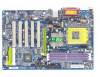
English GA-7VT600(-L) Motherboard Layout KB_MS CPU FAN RAM_LED SOCKET A GA-7VT600 ATX FLOPPY COMA LPT COMB LAN * USB -L AUDIO CODEC SPDIF_IO SUR_CEN RTL8101L* IT8705 GAME F_AUDIO AUX_IN CD_IN KT600 BIOS CI MODEM * AGP PCI1 SW1 PCI2 - Gigabyte GA-7VT600 | User Manual - Page 12
Ports IDE Channels 33 MHz PS/2 KB/Mouse COM Ports MIC LINE-IN LINE-OUT PCICLK (33MHz) USBCLK (48MHz) 14.318 MHz 33 MHz " * " FOR GA-7VT600-L Only. GA-7VT600(-L) Motherboard CLK HCLK+/- (100/133/166/200MHz) CPUCLK+/- (100/133/166/200MHz) GEN AGPCLK (66MHz) V_Link (66MHz) - 8 - - Gigabyte GA-7VT600 | User Manual - Page 13
English Chapter 2 Hardware Installation Process To set up your computer, you must complete the following steps: Step 1- Set Dip Switch (CK_RATIO) and system Switch (SW1) Step 2- Install the Central Processing Unit (CPU) Step 3- Install memory modules Step 4- Install expansion cards Step 5- Connect - Gigabyte GA-7VT600 | User Manual - Page 14
internal frequency depend on CPU.) O: ON / X :OFF ON SW1 Default Setting: 100MHz 1 SW1 CPU CLOCK 100MHz Auto 1 ON OFF 100MHz : Fix FSB 200MHz CPU Auto : Support FSB 266/333 MHz CPU You must set SW1 to 100MHz when you used FSB 200MHz CPU. GA-7VT600(-L) Motherboard - 10 - - Gigabyte GA-7VT600 | User Manual - Page 15
English Step1-2: CPU Installation Before installing the processor, adhere to the following warning: 1.Please make sure the CPU type is supported by the motherboard. 2.If you do not match the CPU socket Pin 1 and CPU cut edge well, it will cause improper installation. Please change the insert - Gigabyte GA-7VT600 | User Manual - Page 16
the installation. Please refer to CPU cooling fan user's manual for more detail installation procedure. 1. Press down the CPU supporting-base onto the CPU socket on the mainboard. 4. Make sure the CPU fan is plugged to the CPU fan connector, than install complete. GA-7VT600(-L) Motherboard - Gigabyte GA-7VT600 | User Manual - Page 17
will cause improper installation. Please change the insert orientation. The motherboard has 3 dual inline memory module(DIMM) sockets. The BIOS direction due to the notch. Memory size can vary between sockets. Notch DDR Support Unbuffered DDR DIMM Sizes type: 64 Mbit (2Mx8x4 banks) 64 Mbit ( - Gigabyte GA-7VT600 | User Manual - Page 18
migration path from existing SDRAM designs due to its availability, pricing and overall market support. PC2100 DDR memory (DDR266) doubles the data rate through reading and writing at a compelling solution for small form factor desktops and notebook applications. GA-7VT600(-L) Motherboard - 14 - - Gigabyte GA-7VT600 | User Manual - Page 19
instruction document before install the expansion card into the computer. 2. Remove your computer's chassis cover, necessary screws and slot bracket from the computer. 3. Press the expansion card firmly into expansion slot in motherboard BIOS. 8. Install related driver from the operating system. - Gigabyte GA-7VT600 | User Manual - Page 20
Ports (COMA / COMB) Parallel Port (25 pin Female) This connector supports 2 standard COM ports and 1 Parallel port. Device like printer can be connected to Parallel port; mouse and modem etc. can be connected to Serial ports. COMA COMB Serial Port (9 pin Male) GA-7VT600(-L) Motherboard - 16 - - Gigabyte GA-7VT600 | User Manual - Page 21
interface. Also make sure your OS supports USB controller. If your OS does not support USB controller, please contact OS vendor for possible patch or driver upgrade. For more information please installation, please refer to page 63. " * " FOR GA-7VT600-L Only. - 17 - Hardware Installation Process - Gigabyte GA-7VT600 | User Manual - Page 22
9) F_PANEL 16 17 18 79 10) F_AUDIO 11) SUR_CEN 12) CD_IN 13) AUX_IN 14) SPDIF_IO 15) F_USB1/F_USB2 16) GAME 17) MODEM * 18) CI " * " FOR GA-7VT600-L Only. GA-7VT600(-L) Motherboard - 18 - - Gigabyte GA-7VT600 | User Manual - Page 23
of the CPU cooler is essential to prevent the CPU from running under abnormal condition or damaged by overheating.The CPU fan connector supports Max. current up to 600 mA. Pin No. Definition 1 GND 1 2 +12V 3 Sense 2) SYS_FAN (System FAN Connector) This connector allows you to link with - Gigabyte GA-7VT600 | User Manual - Page 24
IDE1 and connect CDROM to IDE2. The red stripe of the ribbon cable must be the same side with the Pin1. 40 2 39 1 IDE2 IDE1 GA-7VT600(-L) Motherboard - 20 - - Gigabyte GA-7VT600 | User Manual - Page 25
English 5) FDD (Floppy Connector) Please connect the floppy drive ribbon cables to FDD. It supports 360K,720K,1.2M,1.44M and 2.88Mbytes floppy disk types. The red stripe of the ribbon cable must be the same side with the Pin1. 34 - Gigabyte GA-7VT600 | User Manual - Page 26
2 MPD3 MPD- 8) BATTERY (Battery) GA-7VT600(-L) Motherboard + CAUTION v Danger of explosion if battery is incorrectly replaced. v Replace only with the same or equivalent type recommended by the manufacturer. v Dispose of used batteries according to the manufacturer's instructions. If you want to - Gigabyte GA-7VT600 | User Manual - Page 27
English 9) F_PANEL (2x10 pins connector) Please connect the power LED, PC peaker, reset switch and power switch etc of your chassis front panel to the F_PANEL connector according to the pin assignment above. Message LED/Power/ Sleep LED Soft Power Connector Speaker Connector MSGMSG+ PW- PW+ - Gigabyte GA-7VT600 | User Manual - Page 28
cable is the same as the pin assigment on the MB header. To find out if the chassis you are buying support front audio connector, please contact your dealer. 10 9 21 Pin No. Definition 1 MIC 2 GND 3 REF 1 SUR OUTL 2 SUR OUTR 3 GND 4 No Pin 5 CENTER_OUT 6 BASS_OUT GA-7VT600(-L) Motherboard - 24 - - Gigabyte GA-7VT600 | User Manual - Page 29
English 12) CD_IN (CD IN,Blank) Connect CD-ROM or DVD-ROM audio out to the connector. Pin No. Definition 1 CD-L 2 GND 1 3 GND 4 CD_R 13) AUX_IN ( AUX In Connector) Connect other device(such as PCI TV Tunner audio out)to the connector. Pin No. Definition 1 AUX-L 2 GND 1 3 GND 4 AUX_R - - Gigabyte GA-7VT600 | User Manual - Page 30
contact your local dealer. 2 10 19 Pin No. 1 2 3 4 5 6 7 8 9 10 Definition Power Power USB DXUSB DyUSB DX+ USB Dy+ GND GND No Pin USB Over Current GA-7VT600(-L) Motherboard - 26 - - Gigabyte GA-7VT600 | User Manual - Page 31
English 16) GAME (Game Connector) This connector supports joystick, MIDI keyboard and other relate audio devices. Pin No. Definition 1 VCC 2 GRX1_R 3 GND 1 13 8 VAUX33 9 ACDOUT 10 NC 11 ACSYNC 12 NC 13 ACRSTB 14 No Pin " * " FOR GA-7VT600-L Only. - 27 - Hardware Installation Process - Gigabyte GA-7VT600 | User Manual - Page 32
English 18) CI (CASE OPEN) This 2 pin connector allows your system to enable or disable the "case open" item in BIOS if the system case begin remove. Pin No. Definition 1 Signal 1 2 GND GA-7VT600(-L) Motherboard - 28 - - Gigabyte GA-7VT600 | User Manual - Page 33
- 29 - Hardware Installation Process English - Gigabyte GA-7VT600 | User Manual - Page 34
English GA-7VT600(-L) Motherboard - 30 - - Gigabyte GA-7VT600 | User Manual - Page 35
English Chapter 3 BIOS Setup BIOS Setup is an overview of the BIOS Setup Program. The program that allows users to modify the basic system configuration. This type of information is stored in battery-backed CMOS RAM so that it retains the Setup information when the power is turned off. ENTERING - Gigabyte GA-7VT600 | User Manual - Page 36
BIOS. l Advanced BIOS Features This setup page includes all the items of Award special enhanced features. l Integrated Peripherals This setup page includes all onboard peripherals. GA-7VT600(-L) Motherboard - 32 - - Gigabyte GA-7VT600 | User Manual - Page 37
English l Power Management Setup This setup page includes all the items of Green function features. l PnP/PCI Configurations This setup page includes all the configurations of PCI & PnP ISA resources. l PC Health Status This setup page is the System auto detect Temperature, voltage, fan, speed. l - Gigabyte GA-7VT600 | User Manual - Page 38
IDE Primary Master }IDE Primary Slave }IDE Secondary Master }IDE Secondary Slave Drive A Drive B Floppy 3 Mode Support Standard CMOS Features Thu, Feb 21 2002 22:31:24 [Press Enter None] [Press Enter None] [Press Enter clock. For example, 1 p.m. is 13:00:00. GA-7VT600(-L) Motherboard - 34 - - Gigabyte GA-7VT600 | User Manual - Page 39
There are two types: auto type, and manual type. Manual type is user-definable; Auto type which disk driver changes the write current. 8Landing Zone The cylinder number that the disk driver heads( drive; 2.88M byte capacity. FFloppy 3 Mode Support (for Japan Area) 8Disabled Normal Floppy Drive. - Gigabyte GA-7VT600 | User Manual - Page 40
on the motherboard, or 640 K for systems with 640 K or more memory installed on the motherboard. Extended Memory The BIOS determines how much extended memory is present during the POST. This is the amount of memory located above 1 MB in the CPU's memory address map. GA-7VT600(-L) Motherboard - 36 - Gigabyte GA-7VT600 | User Manual - Page 41
English Advanced BIOS Features CMOS Setup Utility-Copyright (C) 1984-2003 Award Software Advanced BIOS Features First Boot Device [Floppy] Second Boot Device [HDD-0] Third Boot Device [CDROM] Password Check [Setup] Item Help Menu Levelu higf: Move Enter:Select +/-/PU/PD:Value F10:Save - Gigabyte GA-7VT600 | User Manual - Page 42
prompt. 8Setup The system will boot, but access to Setup will be denied if the correct password is not entered at the prompt. (Default value) GA-7VT600(-L) Motherboard - 38 - - Gigabyte GA-7VT600 | User Manual - Page 43
] [Enabled] USB 1.1 Controller USB 2.0 Controller [Enabled] [Enabled] USB Keyboard Support USB Mouse Support [Disabled] [Disabled] Onboard H/W LAN * [Enabled] Onboard LAN Boot ROM * Defaults F7:Optimized Defaults Figure 4: Integrated Peripherals " * " FOR GA-7VT600-L Only. - 39 - BIOS Setup - Gigabyte GA-7VT600 | User Manual - Page 44
a USB keyboard is installed, please set at Enabled. 8Enabled Enabled USB Keyboard Support. 8Disabled Disabled USB Keyboard Support. (Default value) FUSB Mouse Support 8Enabled Enabled USB Mouse Support. 8Disabled Disabled USB Mouse Support. (Default value) GA-7VT600(-L) Motherboard - 40 - - Gigabyte GA-7VT600 | User Manual - Page 45
port and address is 278,Using IRQ5. 83BC/IRQ7 Enable onboard LPT port and address is 3BC,Using IRQ7. 8Disabled Disable onboard parallel port. " * " FOR GA-7VT600-L Only. - 41 - BIOS Setup . - Gigabyte GA-7VT600 | User Manual - Page 46
Mode MThis feature allows you to connect with an advanced print via the port mode it supports. 8SPP Using Parallel port as Standard Parallel Port using IRQ7. (Default Value) 8EPP Using Parallel Set 5 for Midi Port IRQ. Set 10 for Midi Port IRQ.(Default value) GA-7VT600(-L) Motherboard - 42 - - Gigabyte GA-7VT600 | User Manual - Page 47
English Power Management Setup CMOS Setup Utility-Copyright (C) 1984-2003 Award Software Power Management Setup ACPI Suspend Type [S1(POS)] øUSB Device Wake-Up From S3 Disabled Power LED in S1 state [Blinking] Soft-Off by PWRBTN [Instant-off] AC Back Function [Soft-Off] Keyboard Power - Gigabyte GA-7VT600 | User Manual - Page 48
. 8Disabled Disabled this function. (Default value) 8Keyboard 98 If your keyboard have "POWER Key" button, you can press the key to power on your system. GA-7VT600(-L) Motherboard - 44 - - Gigabyte GA-7VT600 | User Manual - Page 49
English FMouse Power On 8Disabled Can't Power on system by Mouse Event. (Default value) 8Enabled Can Power on system by Mouse Event. FPME Event Wake up M When set at Enabled, any PCI-PM event awakes the system from a PCI-PM controlled state. M This feature requires an ATX power supply that - Gigabyte GA-7VT600 | User Manual - Page 50
. FPCI4 IRQ Assignment 8Auto Auto assign IRQ to PCI 4. (Default value) 83,4,5,7,9.,10,11,12,14,15 Set 3,4,5,7,9,10,11,12,14,15 to PCI4. GA-7VT600(-L) Motherboard - 46 - - Gigabyte GA-7VT600 | User Manual - Page 51
English PC Health Status CMOS Setup Utility-Copyright (C) 1984-2003 Award Software PC Health Status Reset Case Open Status [Disabled] Case Opened No VCORE 1.810V DDRVtt 1.248V +3.3V 3.280V + 5V 4.919 V +12V 11.968V 5VSB 5.053V Current System Temperature 27°C Current CPU - Gigabyte GA-7VT600 | User Manual - Page 52
FAN Speed (RPM) Detect Fan speed status automatically. FFan Fail Warning ( CPU / SYSTEM) 8Disabled Don't monitor current fan speed. (Default value) 8Enabled Alarm when stops. GA-7VT600(-L) Motherboard - 48 - - Gigabyte GA-7VT600 | User Manual - Page 53
English Frequency/Voltage Control CMOS Setup Utility-Copyright (C) 1984-2003 Award Software Frequency/Voltage Control Spread Spectrum Modulated [Enabled] CPU Host Clock Control [Disable] øCPU Host Frequency(MHz) 100 øPCI/AGP Frequency(MHz) 33/66 øDRAM Clock(MHz) 133-DDR266 CPU Voltage - Gigabyte GA-7VT600 | User Manual - Page 54
damage to DRAM module when enable this feature. 8Auto Supply voltage as DRAM module reguired. (Default value) 8+0.1V~+.03V Set DIMM voltage from 2.6V~2.8V. GA-7VT600(-L) Motherboard - 50 - - Gigabyte GA-7VT600 | User Manual - Page 55
English Load Fail-Safe Defaults CMOS Setup Utility-Copyright (C) 1984-2003 Award Software }Standard CMOS Features Load Fail-Safe Defaults }Advanced BIOS Features Load Optimized Defaults }Integrated Peripherals Set Supervisor Password }Power Management Setup Set User Password }PnP/PCI - Gigabyte GA-7VT600 | User Manual - Page 56
Figure 10: Load Optimized Defaults FLoad Optimized Defaults Selecting this field loads the factory defaults for BIOS and Chipset Features which the system automatically detects. GA-7VT600(-L) Motherboard - 52 - - Gigabyte GA-7VT600 | User Manual - Page 57
English Set Supervisor/User Password CMOS Setup Utility-Copyright (C) 1984-2003 Award Software }Standard CMOS Features Load Fail-Safe Defaults }Advanced BIOS Features Load Optimized Defaults }Integrated Peripherals Set Supervisor Password }Power Management Setup Set User Password }PnP/PCI - Gigabyte GA-7VT600 | User Manual - Page 58
12: Save & Exit Setup Type "Y" will quit the Setup Utility and save the user setup value to RTC CMOS. Type "N" will return to Setup Utility. GA-7VT600(-L) Motherboard - 54 - - Gigabyte GA-7VT600 | User Manual - Page 59
English Exit Without Saving CMOS Setup Utility-Copyright (C) 1984-2003 Award Software }Standard CMOS Features Load Fail-Safe Defaults }Advanced BIOS Features Load Optimized Defaults }Integrated Peripherals Set Supervisor Password }Power Management Setup Set User Password }PnP/PCI - Gigabyte GA-7VT600 | User Manual - Page 60
English GA-7VT600(-L) Motherboard - 56 - - Gigabyte GA-7VT600 | User Manual - Page 61
English Chapter 4 Technical Reference BIOS Flash Procedure Method 1: Q-Flash Introduction A. What is Q-Flash Utility? Q-Flash utility is a pre-O.S. BIOS flash utility enables users to update its BIOS within BIOS mode, no more fooling around any OS. B. How to use Q-Flash? a. After power on the - Gigabyte GA-7VT600 | User Manual - Page 62
... !Press Enter to Run. !! COPY BIOS Completed -Pass !! Please press any key to continue Congratulation! You have completed the flashed and now can restart system. GA-7VT600(-L) Motherboard - 58 - - Gigabyte GA-7VT600 | User Manual - Page 63
install the Utility. Press here. 1.Click "@BIOS . 2.Click"Start"-"Programs""GIGABYTE"-"@BIOS" (1) (2) Click "P". Click here. 3. Please select @BIOS sever site d. Select the exact model name on your motherboard e. System will automatically download and update the BIOS. - 59 - Technical - Gigabyte GA-7VT600 | User Manual - Page 64
won't boot. c. In method I, if the BIOS file you need cannot be found in @BIOSTM server, please go onto Gigabyte's web site for downloading and updating it according to method II. d. Please note that any interruption during updating will cause system unbooted GA-7VT600(-L) Motherboard - 60 - - Gigabyte GA-7VT600 | User Manual - Page 65
industries. For such a wonderful software, how much it costs? Impossible! It's free! Now, if you buy a Gigabyte's motherboard, you could find this amazing software in the attached driver CD. But please remember, connected to internet at first, then you could have a internet BIOS update from your - Gigabyte GA-7VT600 | User Manual - Page 66
fully supported by EasyTune 4. Please find the products supported list in the web site. *Any "Overclocking action" is at user's risk, Gigabyte Technology will not be responsible for any damage or instability to your processor, motherboard, or any other components. GA-7VT600(-L) Motherboard - 62 - Gigabyte GA-7VT600 | User Manual - Page 67
best sound effect if the stereo output is applied. STEP 1: Connect the stereo speakers or earphone to "Line Out". STEP 2 : After installation of the audio driver, you'll find an icon on the taskbar's status area. Click the audio icon "Sound Effect" from the windows tray at the bottom of the - Gigabyte GA-7VT600 | User Manual - Page 68
channels to "Line Out", the rear channels to "Line In". STEP 2 : After installation of the audio driver, you'll find an icon on the taskbar's status area. Click the audio icon "Sound Effect" from output). Please select the other settings for 4 channels output. GA-7VT600(-L) Motherboard - 64 - - Gigabyte GA-7VT600 | User Manual - Page 69
Out",the rear channels to "Line In", and the Center/Subwoofer channels to "MIC In". MIC In Line Out STEP 2 : After installation of the audio driver, you'll find an icon on the taskbar's status area. Click the audio icon "Sound Effect" from the windows tray at the bottom of the - Gigabyte GA-7VT600 | User Manual - Page 70
, Line In and MIC at the same time. "SURROUND-KIT" is included in the GIGABYTE unique "Audio Combo Kit" as picture. STEP 1 : Insert the "SURROUND-KIT" in the back of the case , and fix it with the screw. STEP 2 : Connect the "SURROUND-KIT" to SUR_CEN on the M/B. GA-7VT600(-L) Motherboard - 66 - - Gigabyte GA-7VT600 | User Manual - Page 71
English STEP 3 : Connect the front channels to back audio panel's "Line Out", the rear channels to SURROUND-KIT's REAR R/L, and the Center/Subwoofer channels to SURROUND-KIT's SUB CENTER. STEP 4 : Click the audio icon "Sound Effect" from the windows tray at the bottom of the screen. STEP 5 : Select - Gigabyte GA-7VT600 | User Manual - Page 72
Output Device (Optional Device) A "SPDIF output" device is available on the motherboard. Cable with rear bracket is provided and could link to the "SPDIF , and fix it with screw. 2. Connect SPDIF device to the motherboard. 3. Connect SPDIF to the SPDIF decoder. GA-7VT600(-L) Motherboard - 68 - - Gigabyte GA-7VT600 | User Manual - Page 73
-Sensing provides audio connectors error-detection function. Install Microsoft DirectX8.1 before to enable Jack-Sensing support for Windows 98/98SE/2000 /ME. Jack-Sensing includes 2 parts: AUTO and MANUAL. Following is an example for 2 channels (Windows XP): Introduction of audio connectors You may - Gigabyte GA-7VT600 | User Manual - Page 74
English If you set wrong with the connectors, the warning message will come out as right picture. Manual setting: If the device picture shows different from what you set, please press "Manual Selection" to set. GA-7VT600(-L) Motherboard - 70 - - Gigabyte GA-7VT600 | User Manual - Page 75
- 71 - Technical Reference English - Gigabyte GA-7VT600 | User Manual - Page 76
English GA-7VT600(-L) Motherboard - 72 - - Gigabyte GA-7VT600 | User Manual - Page 77
Picture below are shown in Windows XP (CD ver 2.21) Insert the driver CD-title that came with your motherboard into your CD-ROM drive, the driver CD-title will auto start and show the installation guide. If not, please double click the CD-ROM device icon in "My computer", and execute the setup - Gigabyte GA-7VT600 | User Manual - Page 78
hang up issue in XP n RealTek LAN Driver * RealTek 10/100 LAN driver for 81xx series chips n RealTek AC97 Audio Driver Audio driver for Realtek AC97 codec chipset n VIA USB 2.0 Controller For VIA VT8233 (VT6203) / VIA VT8235 south bridge " * " FOR GA-7VT600-L Only. GA-7VT600(-L) Motherboard - 74 - - Gigabyte GA-7VT600 | User Manual - Page 79
Face-Wizard New utility for adding BIOS logo n @BIOS Gigabyte windows flash BIOS utility n Acrobat e-Book Useful utility from Adobe n Acrobat Reader Popular utility from Adobe for reading .PDF file format documents n Norton Internet Security(NIS) Integrated utility which - Gigabyte GA-7VT600 | User Manual - Page 80
English SOFTWARE INFORMATION This page list the contects of softwares and drivers in this CD title. HARDWARE INFORMATION This page lists all device you have for this motherboard. CONTACT US Contact us via the information in this page all over the world. GA-7VT600(-L) Motherboard - 76 - - Gigabyte GA-7VT600 | User Manual - Page 81
specific motherboard model, drivers. You also need to go through some rather different steps in the installation process. Therefore, we suggest that you refer to the installation steps in the RAID manual at our website. (Please download it at http://tw.giga-byte.com/support/user_pdf/raid_manual.pdf - Gigabyte GA-7VT600 | User Manual - Page 82
manual and check whether you have connected any cable that is not provided with the motherboard package to the USB Over Current pin in the Front USB Panel. If the cable is your own cable, please remove it from this pin and do not connect any of your own cables to it. GA-7VT600(-L) Motherboard - Gigabyte GA-7VT600 | User Manual - Page 83
computer after system boots up. What do these beeps usually stand for? Answer: The beep codes below may help you identify the possible computer problems. However, they are only for reference purposes. The situations might differ from case to case. gAMI BIOS Beep Codes *Computer gives 1 short beep - Gigabyte GA-7VT600 | User Manual - Page 84
trouble during boot up, please follow the troubleshooting procedures . START Turn off the power and unplug the AC power cable, then remove all of the add-on cards and cables from motherboard. Please make sure motherboard ATX power cable and turn on the system. A GA-7VT600(-L) Motherboard - 80 - - Gigabyte GA-7VT600 | User Manual - Page 85
If the above procedure unable to solve your problem, please contact with your local retailer or national distributor for help. Or, you could submit your question to the service mail via Gigabyte website technical support zone (http://www.gigabyte.com.tw). The appropriate response will be provided - Gigabyte GA-7VT600 | User Manual - Page 86
& English Technical Support/RMA Sheet Customer/Country: Contact Person: Company: E-mail Add. : Model name/Lot Number: BIOS Network AMR / CNR Keyboard Mouse Power supply Other Device Phone No.: PCB revision: Driver/Utility: Problem Description: & GA-7VT600(-L) Motherboard - 82 - - Gigabyte GA-7VT600 | User Manual - Page 87
English Appendix E: Acronyms Acronyms Meaning ACPI Advanced Configuration and Power Interface APM Advanced Power Management AGP Accelerated Graphics Port AMR Audio Modem Riser ACR Advanced Communications Riser BIOS Basic Input / Output System CPU Central Processing Unit CMOS - Gigabyte GA-7VT600 | User Manual - Page 88
Power-On Self Test Peripheral Component Interconnect Rambus in-line Memory Module Special Circumstance Instructions Single Edge Contact Cartridge Static Random Access Memory Symmetric Multi-Processing System Management Interrupt Universal Serial Bus Voltage ID GA-7VT600(-L) Motherboard - 84 - - Gigabyte GA-7VT600 | User Manual - Page 89
- 85 - Appendix English - Gigabyte GA-7VT600 | User Manual - Page 90
English GA-7VT600(-L) Motherboard - 86 - - Gigabyte GA-7VT600 | User Manual - Page 91
- 87 - Appendix English - Gigabyte GA-7VT600 | User Manual - Page 92
English GA-7VT600(-L) Motherboard - 88 - - Gigabyte GA-7VT600 | User Manual - Page 93
- 89 - Appendix English - Gigabyte GA-7VT600 | User Manual - Page 94
English GA-7VT600(-L) Motherboard - 90 - - Gigabyte GA-7VT600 | User Manual - Page 95
- 91 - Appendix English - Gigabyte GA-7VT600 | User Manual - Page 96
Address: www.gigabyte.com.cn Beijing Office Tel:86-10-82856054 86-10-82856064 86-10-82856094 Fax: 86-10-82856575 Web Address: www.gigabyte.com.cn E-mail:[email protected] Chengdu Office Tel: 86-28-85236930 Fax: 86-28-85256822 Web Address: www.gigabyte.com.cn GA-7VT600(-L) Motherboard - 92
-
 1
1 -
 2
2 -
 3
3 -
 4
4 -
 5
5 -
 6
6 -
 7
7 -
8
-
9
-
10
-
11
-
12
-
13
-
14
-
15
-
16
-
17
-
18
-
19
-
20
-
21
-
22
-
23
-
24
-
25
-
26
-
27
-
28
-
29
-
30
-
31
-
32
-
33
-
34
-
35
-
36
-
37
-
38
-
39
-
40
-
41
-
42
-
43
-
44
-
45
-
46
-
47
-
48
-
49
-
50
-
51
-
52
-
53
-
54
-
55
-
56
-
57
-
58
-
59
-
60
-
61
-
62
-
63
-
64
-
65
-
66
-
67
-
68
-
69
-
70
-
71
-
72
-
73
-
74
-
75
-
76
-
77
-
78
-
79
-
80
-
81
-
82
-
83
-
84
-
85
-
86
-
87
-
88
-
89
-
90
-
91
-
92
-
93
-
94
-
95
-
96
 |
 |

When you installing AGP card, please make sure the following
notice is fully understood and practiced. If your AGP card has
"AGP 4X/8X(1.5V) notch"(show below), please make sure your AGP
card is AGP 4X/8X(1.5V).
Caution: AGP 2X(3.3V) card is not supported by VIA
®
KT600. You
might experience system unable to boot up normally. Please insert
an AGP 4X/8X(1.5V) card
Example 1: Diamond Vipper V770 golden finger is compatible with
2X/4X mode AGP slot. It can be switched between AGP 2X(3.3V) or 4X
(1.5V) mode by adjusting the jumper. The factory default for this card is
2X(3.3V).
The GA-7VT600(-L) (or any AGP 4X only) motherboards might not
function properly, if you install this card without switching the jumper to
4X(1.5V) mode in it.
Example 2: Some ATi Rage 128 Pro graphics cards made by "Power
Color", the graphics card manufacturer & some SiS 305 cards, their
golden finger is compatible with 2X(3.3V)/4X(1.5V) mode AGP slot, but
they support 2X(3.3V) only. The GA-7VT600(-L) (or any AGP 4X only)
motherboards might not function properly, If you install this card in it.
Note : Although Gigabyte's AG32S(G) graphics card is based on
ATi Rage 128 Pro chip, the design of AG32S(G) is compliance
with AGP 4X(1.5V) specification. Therefore, AG32S (G)will work
fine with VIA
®
KT600 based motherboards.
AGP 4X/8X notch