Gigabyte GA-870A-UD3 Manual
Gigabyte GA-870A-UD3 Manual
 |
UPC - 818313010346
View all Gigabyte GA-870A-UD3 manuals
Add to My Manuals
Save this manual to your list of manuals |
Gigabyte GA-870A-UD3 manual content summary:
- Gigabyte GA-870A-UD3 | Manual - Page 1
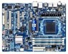
GA-870A-UD3 AM3 socket motherboard for AMD Phenom™ II processor/ AMD Athlon™ II processor User's Manual Rev. 3001 12ME-870AU3-3001R - Gigabyte GA-870A-UD3 | Manual - Page 2
Motherboard GA-870A-UD3 Jan. 14, 2011 Motherboard GA-870A-UD3 Jan. 14, 2011 - Gigabyte GA-870A-UD3 | Manual - Page 3
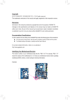
at: http://www.gigabyte.com Identifying Your Motherboard Revision The revision number on your motherboard looks like this: "REV: X.X." For example, "REV: 1.0" means the revision of the motherboard is 1.0. Check your motherboard revision before updating motherboard BIOS, drivers, or when looking - Gigabyte GA-870A-UD3 | Manual - Page 4
-UD3 Motherboard Layout 7 GA-870A-UD3 Motherboard Block Diagram 8 Chapter 1 Hardware Installation 9 1-1 Installation Precautions 9 1-2 Product Specifications 10 1-3 Installing the CPU and CPU Cooler 13 1-3-1 Installing the CPU 13 1-3-2 Installing the CPU Cooler 15 1-4 Installing the Memory - Gigabyte GA-870A-UD3 | Manual - Page 5
5-1 Configuring SATA Hard Drive(s 75 5-1-1 Configuring AMD SB850 SATA Controller 75 5-1-2 Configuring GIGABYTE SATA2/JMicron JMB362 SATA Controller 81 5-1-3 Making a SATA RAID/AHCI Driver Diskette 87 5-1-4 Installing the SATA RAID/AHCI Driver and Operating System 89 5-2 Configuring Audio Input - Gigabyte GA-870A-UD3 | Manual - Page 6
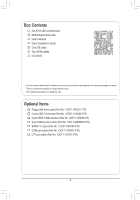
Box Contents GA-870A-UD3 motherboard Motherboard driver disk User's Manual Quick Installation Guide One IDE cable Two SATA cables I/O Shield • The box contents above are for reference only and the actual items shall depend on the product package - Gigabyte GA-870A-UD3 | Manual - Page 7
GA-870A-UD3 Motherboard Layout KB_USB RCA_SPDIF CPU_FAN ATX_12V_2X4 USB_1394_ESATA_2 USB_1394_ESATA_1 R_USB USB30_LAN Renesas PCI3 COMA LPT Socket AM3 PWR_FAN ATX GA-870A-UD3 AMD 870 DDR3_1 DDR3_2 DDR3_3 DDR3_4 IDE FDD GIGABYTE SATA2 BAT CLR_CMOS AMD SB850 SATA3_5 SATA3_4 SATA3_0 - Gigabyte GA-870A-UD3 | Manual - Page 8
x1 1 PCI Express x4 Dual BIOS PCI Bus TSB43AB23 AM3 CPU DDR3 2000(O.C.)/1333/1066 MHz Dual Channel Memory Hyper Transport 3.0 AMD 870 LAN RJ45 2 SATA 3Gb/s Realtek RTL8111D/E x1 GIGABYTE SATA2 x1 ATA-133/100/66/33 IDE Channel PCIe CLK (100 MHz) PCI Express Bus 12 USB 2.0/1.1 AMD SB850 - Gigabyte GA-870A-UD3 | Manual - Page 9
discharge (ESD) wrist strap when handling electronic com- ponents such as a motherboard, CPU or memory. If you do not have an ESD wrist strap, keep your hands dry uncertain about any installation steps or have a problem related to the use of the product, please consult a certified computer technician - Gigabyte GA-870A-UD3 | Manual - Page 10
AM3 processors: AMD Phenom™ II processor/ AMD Athlon™ II processor (Go to GIGABYTE's website for the latest CPU support list.) Hyper Transport Bus 5200 MT/s Chipset Memory Audio North Bridge: AMD 870 South Bridge: AMD SB850 4 x 1.5V DDR3 DIMM sockets - Gigabyte GA-870A-UD3 | Manual - Page 11
-pin ATX main power connector Connectors w 1 x 8-pin ATX 12V power connector w 1 x floppy disk drive connector w 1 x IDE connector w 6 x SATA 6Gb/s connectors w 2 x SATA 3Gb/s connectors w 1 x CPU fan header w 2 x system fan headers w 1 x power fan header - Gigabyte GA-870A-UD3 | Manual - Page 12
memory size displayed will be less than 4 GB. (Note 2) The PCIEX1_1 and PCIEX1_2 slots share bandwidth with the PCIEX4 slot. When the PCIEX4 slot is populated with a x4 card, the PCIEX1_1 and PCIEX1_2 slots become unavailable. (Note 3) Whether the CPU/system fan speed control function is supported - Gigabyte GA-870A-UD3 | Manual - Page 13
before you begin to install the CPU: • Make sure that the motherboard supports the CPU. (Go to GIGABYTE's website for the latest CPU support list.) • Always turn off the computer and unplug the power cord from the power outlet before installing the CPU to prevent hardware damage. • Locate the - Gigabyte GA-870A-UD3 | Manual - Page 14
below to correctly install the CPU into the motherboard CPU socket. • Before installing the CPU, make sure to turn off the computer and unplug the power cord from the power outlet to prevent damage to the CPU. • Do not force the CPU into the CPU socket. The CPU cannot fit in if oriented incorrectly - Gigabyte GA-870A-UD3 | Manual - Page 15
lock into place. (Refer to your CPU cooler installation manual for instructions on installing the cooler.) Step 5: Finally, attach the power connector of the CPU cooler to the CPU fan header (CPU_FAN) on the motherboard. Use extreme care when removing the CPU cooler because the thermal grease/tape - Gigabyte GA-870A-UD3 | Manual - Page 16
. If you are unable to insert the memory, switch the direction. 1-4-1 Dual Channel Memory Configuration This motherboard provides four DDR3 memory sockets and supports Dual Channel Technology. After the memory is installed, the BIOS will automatically detect the specifications and capacity of - Gigabyte GA-870A-UD3 | Manual - Page 17
to install DDR3 DIMMs on this motherboard. Notch DDR3 DIMM A DDR3 memory module has a notch, so it can only fit in one direction. Follow the steps below to correctly install your memory modules in the memory sockets. Step 1: Note the orientation of the memory module. Spread the retaining clips at - Gigabyte GA-870A-UD3 | Manual - Page 18
read the manual that came with your expansion card. • Always turn off the computer and unplug the power cord from the power outlet before installing an expansion card to prevent hardware damage. PCI Express x1 Slot PCI Express x16 Slot (PCIEX16) PCI Express x16 Slot (PCIEX4) PCI Slot Follow - Gigabyte GA-870A-UD3 | Manual - Page 19
out to an external audio system that supports digital coaxial audio. Before using this 5, "Configuring SATA Hard Drive(s)," for instructions on configuring a RAID array. RJ-45 LAN Port The Gigabit from your device and then remove it from the motherboard. • When removing the cable, pull it straight - Gigabyte GA-870A-UD3 | Manual - Page 20
The USB 3.0 port supports the USB 3.0 specification a 5.1/7.1-channel audio configuration. Rear Speaker Out Jack (Black) Use this audio jack to connect rear speakers in a 7.1-channel audio default Mic in jack ( ). Refer to the instructions on setting up a 2/4/5.1/7.1-channel audio configuration in - Gigabyte GA-870A-UD3 | Manual - Page 21
13 5 2 7 12 6 10 9 15 4 13 8 14 4 18 19 17 16 20 11 1) ATX_12V_2X4 2) ATX 3) CPU_FAN 4) SYS_FAN1/2 5) PWR_FAN 6) FDD 7) IDE 8) SATA3_0/1/2/3/4/5 9) GSATA2_6/7 10) BAT 11) F_PANEL 12) F_AUDIO has been securely attached to the connector on the motherboard. - 21 - Hardware Installation - Gigabyte GA-870A-UD3 | Manual - Page 22
ATX (2x4 12V Power Connector and 2x12 Main Power Connector) With the use of the power connector, the power supply can supply enough stable power to all the components on the motherboard . The 12V power connector mainly supplies power to the CPU. If the 12V power connector is not connected, the - Gigabyte GA-870A-UD3 | Manual - Page 23
(the black connector wire is the ground wire). The motherboard supports CPU fan speed control, which requires the use of a CPU fan with fan speed control design. For optimum heat dissipation, it is recom- mended that a system fan be installed inside the chassis. CPU_FAN: Pin No. Definition - Gigabyte GA-870A-UD3 | Manual - Page 24
1.5Gb/s standards. Each SATA connector supports a single SATA device. The AMD SB850 controller supports RAID 0, RAID 1, RAID 5, RAID 10, and JBOD. Refer to Chapter 5, "Configuring SATA Hard Drive(s)," for instructions on configuring a RAID array. SATA3_5 1 7 1 7 SATA3_4 SATA3_0 1 SATA3_3 - Gigabyte GA-870A-UD3 | Manual - Page 25
and are compatible with SATA 1.5Gb/s standard. Each SATA connector supports a single SATA device. The GIGABYTE SATA2 supports RAID 0 and RAID 1. Refer to Chapter 5, "Configuring SATA Hard Drive(s)," for instructions on configuring a RAID array. G.QBOFM GSATA2_6 7 1 7 1 GSATA2_7 Pin No - Gigabyte GA-870A-UD3 | Manual - Page 26
status by issuing a beep code. One single short beep will be heard if no problem is detected at system startup. If a problem is detected, the BIOS may issue beeps in different patterns to indicate the problem. Refer to Chapter 5, "Troubleshooting," for information about beep codes. • HD (Hard Drive - Gigabyte GA-870A-UD3 | Manual - Page 27
pin assignments of the motherboard header. Incorrect connection between the module connector and the motherboard header will make the device front panel audio header supports HD audio by default. If your chassis provides an AC'97 front panel audio module, refer to the instructions on how to activate - Gigabyte GA-870A-UD3 | Manual - Page 28
. Definition 1 Power 2 SPDIFI 3 GND 15) SPDIF_OUT (S/PDIF Out Header) This header supports digital S/PDIF Out and connects a S/PDIF digital audio cable (provided by expansion cards) for digital audio output from your motherboard to certain expansion cards like graphics cards and sound cards. For - Gigabyte GA-870A-UD3 | Manual - Page 29
DY+ 7 GND 8 GND 9 No Pin 10 NC When the system is in S4/S5 mode, only the USB ports routed to the F_USB1 header can support the ON/OFF Charge function. • Do not plug the IEEE 1394 bracket (2x5-pin) cable into the USB header. • Prior to installing the USB bracket - Gigabyte GA-870A-UD3 | Manual - Page 30
18) COMA (Serial Port Header) The COM header can provide one serial port via an optional COM port cable. For purchasing the optional COM port cable, please contact the local dealer. DEBUG PORT Pin No. Definition 1 NDCD- 9 1 2 NSIN 10 2 3 NSOUT 4 NDTR- 5 GND 6 NDSR- 7 NRTS- 8 NCTS- 9 - Gigabyte GA-870A-UD3 | Manual - Page 31
the jumper. Failure to do so may cause damage to the motherboard. • After system restart, go to BIOS Setup to load factory defaults (select Load Optimized Defaults) or manually configure the BIOS settings (refer to Chapter 2, "BIOS Setup," for BIOS configurations). - 31 - Hardware Installation - Gigabyte GA-870A-UD3 | Manual - Page 32
Hardware Installation - 32 - - Gigabyte GA-870A-UD3 | Manual - Page 33
that searches and downloads the latest version of BIOS from the Internet and updates the BIOS. For instructions on using the Q-Flash and @BIOS utilities, refer to Chapter 4, "BIOS Update Utilities." • Because BIOS flashing is potentially risky, if you do not encounter problems using the current - Gigabyte GA-870A-UD3 | Manual - Page 34
Keys B. The POST Screen Motherboard Model BIOS Version Award Modular BIOS v6.00PG Copyright (C) 1984-2010, Award Software, Inc. AMD 870 BIOS for GA-870A-UD3 D1 . . . . : BIOS Setup : XpressRecovery2 : Boot Menu : Qflash 12/14/2010-RX870-SB850-7A66CG0EC-00 Function Keys - Gigabyte GA-870A-UD3 | Manual - Page 35
F10: Save & Exit Setup Change CPU's Clock & Voltage F11: Save CMOS to BIOS F12: Load CMOS from BIOS BIOS Setup Program Function Keys Move the changes and exit the BIOS Setup program Save CMOS to BIOS Load CMOS from BIOS Main Menu Help The on-screen description of - Gigabyte GA-870A-UD3 | Manual - Page 36
CPU, memory, etc. Standard CMOS Features Use this menu to configure the system time and date, hard drive types, floppy disk drive types, and the type of errors that stop the system boot, etc. Advanced BIOS information about autodetected system/CPU temperature, system voltage and fan speed, etc. - Gigabyte GA-870A-UD3 | Manual - Page 37
Control Enables or disables the control of CPU host clock. Auto (default) allows the BIOS to automatically adjust the CPU host frequency. Manual allows the CPU Frequency (MHz) item below to be configurable. Note: If your system fails to boot after overclocking, please wait for 20 seconds to allow - Gigabyte GA-870A-UD3 | Manual - Page 38
PCIe Spread Spectrum. (Default: Disabled) HT Link Frequency Allows you to manually set the frequency for the HT Link between the CPU and chipset. Auto BIOS will automatically adjust the HT Link Frequency. (Default) x1~x10 Sets HT Link Frequency to x1~x10 (200 MHz~2.0 GHz). Set Memory Help - Gigabyte GA-870A-UD3 | Manual - Page 39
increase memory performance and stability. (Default: Enabled) Channel interleave Enables or disables memory channel interleaving. Enabled allows the system to simultaneously access different channels of the memory to increase memory performance and stability. (Default: Enabled) - 39 - BIOS Setup - Gigabyte GA-870A-UD3 | Manual - Page 40
the system voltages. Auto lets the BIOS automatically set the system voltages as required. Manual allows all voltage control items below to be configurable. (Default: Auto) DRAM Voltage Control Allows you to set the memory voltage. Normal Supplies the memory voltage as required. (Default) 1.500V - Gigabyte GA-870A-UD3 | Manual - Page 41
None] [None] [None] [None] [None] [None] Drive A Floppy 3 Mode Support [1.44M, 3.5"] [Disabled] Move Enter: Select F5: Previous Values +/-/PU/PD: Value Features Halt On Base Memory Extended Memory [All, But Keyboard] 640K 1022M Item Help Menu Level Move BIOS Setup - Gigabyte GA-870A-UD3 | Manual - Page 42
wish to enter the parameters manually, refer to the information on ", 720K/3.5", 1.44M/3.5", 2.88M/3.5". Floppy 3 Mode Support Allows you to specify whether the installed floppy disk Memory These fields are read-only and are determined by the BIOS POST. Base Memory Also called conventional memory - Gigabyte GA-870A-UD3 | Manual - Page 43
Setup Utility-Copyright (C) 1984-2010 Award Software Advanced BIOS Features AMD C1E Support (Note) Virtualization AMD K8 Cool&Quiet control CPU Unlock (Note) CPU core Control x CPU core 0 x CPU core 1 x CPU core 2/3/4/5 (Note) } Hard Disk Boot Priority First Boot - Gigabyte GA-870A-UD3 | Manual - Page 44
XP PCI graphics card or the PCI Express graphics card. PCI Slot Sets the PCI graphics card as the first display. (Default) PEG Sets the PCI Express graphics card on the PCIEX16 slot as the first display. PEG1 Sets the PCI Express graphics card on the PCIEX4 slot as the first display. BIOS - Gigabyte GA-870A-UD3 | Manual - Page 45
to install operating systems that support Native mode. RAID Enables RAID for the SATA controller. AHCI Configures the SATA controllers to AHCI mode. Advanced Host Controller Interface (AHCI) is an interface specification that allows the storage driver to enable advanced Serial - Gigabyte GA-870A-UD3 | Manual - Page 46
or AHCI. Configures the oper- ating mode of the integrated SATA3_4/SATA3_5 connectors. IDE Disables RAID for the SATA controller and configures the SATA controller to PATA mode. (Default) As SATA Type The mode depends on the OnChip SATA Type settings. OnChip SATA RAID5 Support (AMD SB850 - Gigabyte GA-870A-UD3 | Manual - Page 47
AHCI mode. Advanced Host Controller Interface (AHCI) is an interface specification that allows the storage driver to enable advanced Serial ATA features such as Native Command Queuing and hot plug. RAID Enables RAID General Help F7: Optimized Defaults This motherboard BIOS Setup - Gigabyte GA-870A-UD3 | Manual - Page 48
When a Cable Problem Occurs... If a cable problem occurs on a specified pair of wires, the Status field will show Short and then length shown will be the approximate This item is configurable only when Parallel Port Mode is set to ECP or ECP+EPP mode. Options are: 3 (default), 1. BIOS Setup - 48 - - Gigabyte GA-870A-UD3 | Manual - Page 49
HPET Support (hh:mm:ss) ErP Support [S3(STR)] [Instant- 0 [Disabled] Item Help Menu Level Move Help (Suspend to RAM) sleep state PCI or PCIe device. Note: To use this function, you need an ATX power supply providing at least 1A on the +5VSB lead. (Default: Enabled) (Note) Supported - Gigabyte GA-870A-UD3 | Manual - Page 50
by a PS/2 keyboard wake-up event. Note: you need an ATX power supply providing at least 1A on the +5VSB lead. Disabled is turned on upon the return of the AC power. Memory The system returns to its last known awake state upon Supported on Windows 7/Vista operating system only. BIOS Setup - 50 - - Gigabyte GA-870A-UD3 | Manual - Page 51
CPU Smart FAN Mode System Smart FAN Control [Auto] [Enabled] Item Help Help F7: Optimized Defaults Hardware Thermal Control Enables or disables the CPU overheating protection function. When enabled, the CPU core voltage and ratio will be reduced when the CPU to the motherboard CI header. - Gigabyte GA-870A-UD3 | Manual - Page 52
the CPU fan runs at full speed. (Default: Enabled) CPU Smart FAN Mode Specifies how to control CPU fan speed. This item is configurable only when CPU Smart FAN Control is set to Enabled. Auto Lets the BIOS automatically detect the type of CPU fan installed and sets the optimal CPU fan control - Gigabyte GA-870A-UD3 | Manual - Page 53
stable BIOS settings for the motherboard. BIOS F12: Load CMOS from BIOS Press on this item and then press the key to load the optimal BIOS default settings. The BIOS defaults settings help the system to operate in optimum state. Always load the Optimized defaults after updating the BIOS - Gigabyte GA-870A-UD3 | Manual - Page 54
changes. When the Password Check item is set to System, you must enter the supervisor password (or user password) at system startup and when entering BIOS Setup. User Password When the Password Check item is set to System, you must enter the supervisor password (or user password) at system startup - Gigabyte GA-870A-UD3 | Manual - Page 55
Setup PC Health Status Exit Without Saving ESC: Quit F8: Q-Flash Select Item F10: Save & Exit Setup Save Data to CMOS F11: Save CMOS to BIOS F12: Load CMOS from BIOS Press on this item and press the key. This saves the changes to the CMOS and exits the - Gigabyte GA-870A-UD3 | Manual - Page 56
BIOS Setup - 56 - - Gigabyte GA-870A-UD3 | Manual - Page 57
install new GIGABYTE utilities. Click Yes to automatically install the utilities. Or click No if you want to manually select the utilities to install on the Application Software page later. • For USB 2.0 driver support under the Windows XP operating system, please install the Windows XP Service Pack - Gigabyte GA-870A-UD3 | Manual - Page 58
applications that GIGABYTE develops and some free software. You can click the Install button on the right of an item to install it. 3-3 Technical Manuals This page provides GIGABYTE's application guides, content descriptions for this driver disk, and the motherboard manuals. Drivers Installation - Gigabyte GA-870A-UD3 | Manual - Page 59
3-4 Contact For the detailed contact information of the GIGABYTE Taiwan headquarter or worldwide branch offices, click the URL on this page to link to the GIGABYTE website. 3-5 System This page provides the basic system information. - 59 - Drivers Installation - Gigabyte GA-870A-UD3 | Manual - Page 60
Center To update the BIOS, drivers, or applications, click the Download Center button to link to the GIGABYTE website. The latest version of the BIOS, drivers, or applications will be displayed. 3-7 New Utilities This page provides a quick link to GIGABYTE's lately developed utilities for users - Gigabyte GA-870A-UD3 | Manual - Page 61
system and drivers are installed. • XP with SP1 or later, Windows Vista • Xpress Recovery and Xpress Recovery2 are different utilities. For example, a backup file created with Xpress Recovery cannot be restored using Xpress Recovery2. • USB hard drives are not supported. • Hard drives in RAID/AHCI - Gigabyte GA-870A-UD3 | Manual - Page 62
note that if there is no enough unallocated space, Xpress Recovery2 cannot save the backup file. B. Accessing Xpress Recovery2 1. Boot from the motherboard driver disk to access Xpress Recovery2 for the first time. When you see the following message: Press any key to startup Xpress Recovery2, press - Gigabyte GA-870A-UD3 | Manual - Page 63
D. Using the Restore Function in Xpress Recovery2 Select RESTORE to restore the backup to your hard drive in case the system breaks down. The RESTORE option will not be present if no backup is created before. E. Removing the Backup Step 1: If you wish to remove the backup file, select REMOVE. Step - Gigabyte GA-870A-UD3 | Manual - Page 64
. However, if the BIOS update file is saved to a hard drive in RAID/AHCI mode or a hard drive attached to an independent IDE/SATA controller, use the key during the POST to access Q-Flash. Award Modular BIOS v6.00PG Copyright (C) 1984-2010, Award Software, Inc. AMD 870 BIOS for GA-870A-UD3 D1 - Gigabyte GA-870A-UD3 | Manual - Page 65
key to select Update BIOS from Drive and press . • The Save Main BIOS to Drive option allows you to save the current BIOS file. • Q-Flash only supports USB flash drive or hard drives using FAT32/16/12 file system. • If the BIOS update file is saved to a hard drive in RAID/AHCI mode or a hard - Gigabyte GA-870A-UD3 | Manual - Page 66
. Step 5: During the POST, press to enter BIOS Setup. Select Load Optimized Defaults and press to load BIOS defaults. System will re-detect all peripheral devices after a BIOS update, so we recommend that you reload BIOS defaults. CMOS Setup Utility-Copyright (C) 1984-2010 Award - Gigabyte GA-870A-UD3 | Manual - Page 67
. If the BIOS update file for your motherboard is not present on the @BIOS server site, please manually download the BIOS update file from GIGABYTE's website and follow the instructions in "Update the BIOS without Using the Internet Update Function" below. 2. Update the BIOS without Using the - Gigabyte GA-870A-UD3 | Manual - Page 68
in EasyTune 6 may differ by motherboard model. Grayed-out area(s) indicates that the item is not configurable or the function is not supported. Incorrectly doing overclock/overvoltage may result in damage to the hardware components such as CPU, chipset, and memory and reduce the useful life of - Gigabyte GA-870A-UD3 | Manual - Page 69
Easy Energy Saver Interface A. Meter Mode In Meter Mode, GIGABYTE Easy Energy Saver shows how much power they have saved in Help 15 Live Utility Update (Check for the latest utility version) • The above data is for reference only. Actual performance may vary depending on motherboard model. • CPU - Gigabyte GA-870A-UD3 | Manual - Page 70
(Application will continue to run in taskbar) 13 INFO/Help 14 Live Utility Update (Check for the latest utility version) C. Stealth Mode close the application. (Note 1) Maximize system power saving with Dynamic CPU Frequency Function; system performance may be affected. (Note 2) 1: Normal - Gigabyte GA-870A-UD3 | Manual - Page 71
for using Q-Share After installing Q-Share from the motherboard driver disk, go to Start>All Programs>GIGABYTE>Q-Share. exe to launch the Q-Share tool. shared data folder Changes the data folder to be shared (Note) Updates Q-Share online Displays the current Q-Share version Exits Q-Share ( - Gigabyte GA-870A-UD3 | Manual - Page 72
up to 64 backups (the actual limit depends on the size of each partition). When this limit is reached, the oldest backup will be ovewritten. Instructions for copying files/folders from a backup: To browse through your backups made at different time, select a backup time using the time scroll bar on - Gigabyte GA-870A-UD3 | Manual - Page 73
Standby Suspend Disable Description Enters Power on Suspend mode Enters Suspend to RAM mode Disables this function The Bluetooth dongle included in the motherboard package(Note 2) allows you to wake up the system from Suspend to RAM mode without the need to press the power button first. (Note - Gigabyte GA-870A-UD3 | Manual - Page 74
Unique Features - 74 - - Gigabyte GA-870A-UD3 | Manual - Page 75
identical model and capacity). If you do not want to create RAID, you may prepare only one hard drive. • An empty formatted floppy disk. • Windows Vista/XP setup disk. • Motherboard driver disk. 5-1-1 Configuring AMD SB850 SATA Controller A. Installing SATA hard drive(s) in your computer Attach one - Gigabyte GA-870A-UD3 | Manual - Page 76
(Figure 1). To enable support for RAID 5, set OnChip SATA RAID5 Support to Enabled. CMOS Setup Help F7: Optimized Defaults Figure 1 Step 2: Save changes and exit BIOS Setup. The BIOS Setup menus described in this section may differ from the exact settings for your motherboard. The actual BIOS - Gigabyte GA-870A-UD3 | Manual - Page 77
C. Configuring RAID set in RAID BIOS Enter the RAID BIOS setup utility to configure a RAID array. Skip this step and proceed with the installation of Windows operating system for a non-RAID configuration. Step 1: After the POST memory test begins and before the operating system boot begins, look - Gigabyte GA-870A-UD3 | Manual - Page 78
Create Arrays Manually To create a new array, press to enter the LD View Menu window (Figure Devices, Inc. LD No LD Name LD 1 Logical Drive 1 [ LD Define Menu ] RAID Mode Drv RAID 0 0 Stripe Block: 64 KB Gigabyte Boundary: ON Fast Init: ON Cache Mode: WriteThru Port:ID 01:00 02:00 [ - Gigabyte GA-870A-UD3 | Manual - Page 79
7 7. Then, the message in Figure 8 will appear. Press + to set the capacity of the RAID array or press other keys to set the array to its maximum capacity. Press Ctrl-Y to Modify Array Capacity or Main Menu and press again if you want to exit the RAID BIOS utility. - 79 - Appendix - Gigabyte GA-870A-UD3 | Manual - Page 80
>to return to Main Menu. Option ROM Utility (c) 2009 Advanced Micro Devices, Inc. LD No LD Name [ View LD Defination Menu ] RAID Mode Drv Capacity(GB) LD 1 GBT RAID 0 2 80 Stripe Block: 64 KB Cache Mode: WriteThru Port:ID 01:00 02:00 [ Drives Assignments ] Drive Model WDC WD800JD - Gigabyte GA-870A-UD3 | Manual - Page 81
the table below for configuring different SATA Controllers for RAID. Controller Connectors GIGABYTE GSATA2_6/7 SATA2 JMicron eSATA ports JMB362 BIOS Settings Set Onboard GSATA/IDE Ctrl to Enabled Set Onboard GSATA/IDE Mode to RAID/IDE Set Onboard ESATA controller to Enabled Set Onboard ESATA - Gigabyte GA-870A-UD3 | Manual - Page 82
configuration. After the POST memory test begins and before the operating system boot begins, look for a message which says "Press to enter RAID Setup Utility" (Figure 2). Press + to enter the RAID setup utility. GIGABYTE Technology Corp. PCI Express to SATAII Host Controller - Gigabyte GA-870A-UD3 | Manual - Page 83
Available 120 GB 120 GB Type/Status Non-RAID Non-RAID Confirm Creation [ RAID Disk Drive List ] [ Help ] Enter RAID Name Enter a string between 1 to 16 characters in length for the created RAID drive to be identified by system BIOS or OS. [fg]-Move Cursor [DEL,BS]-Delete - Gigabyte GA-870A-UD3 | Manual - Page 84
a RAID mode is selected, RAID BIOS automatically assigns the two hard drives installed as the RAID drives. 4. Set Block Size (RAID 0 only): Under the Block item, use the up or down arrow key to select the stripe block size (Figure 6), ranging from 4 KB to 128 KB. Press . Gigabyte Technology - Gigabyte GA-870A-UD3 | Manual - Page 85
the array information will appear in the center of the screen (Figure 9). Gigabyte Technology Corp. RAID Setup Utility v1.07.16G [ Main Menu ] Create RAID Disk Drive Delete RAID Disk Drive Revert HDD to Non-RAID Solve Mirror Conflict Rebuild Mirror Drive Save And Exit Setup Exit Without Saving - Gigabyte GA-870A-UD3 | Manual - Page 86
10 [ENTER]-Action [ESC]-Exit Now, you may proceed to create the SATA RAID/AHCI driver diskette and the installation of the SATA RAID/ AHCI driver and operating system. Delete the RAID Array: To delete the array, select Delete RAID Disk Drive in the main menu and press . The selection bar - Gigabyte GA-870A-UD3 | Manual - Page 87
and the motherboard driver disk (here we as- sume that the drive letter for your optical drive is D:\). 3: At the A:\> prompt, type the following command. Press after the command: • For the AMD SB850, type (Figure 1): (Note 1) A:\>copy d:\bootdrv\SB8xx\x86\*.* • For the GIGABYTE SATA2 - Gigabyte GA-870A-UD3 | Manual - Page 88
Steps: 1: Use an alternative system and insert the motherboard driver disk. 2: From your optical drive folder, double • For the AMD SB850, select 3) ATi AHCI/RAID Driver for XP for Windows XP operating system. • For the GIGABYTE SATA2/JMicron JMB362, select 1) GIGABYTE GSATA driver for 32bit system - Gigabyte GA-870A-UD3 | Manual - Page 89
you to specify additional device. Windows Setup Press F6 if you need to install a third party SCSI or RAID driver. Figure 1 Step 2: For the AMD SB850: Insert the floppy disk containing the SATA RAID/AHCI driver and press . Then a controller menu similar to Figure 2 below will appear. Select - Gigabyte GA-870A-UD3 | Manual - Page 90
a SCSI Adapter for use with Windows, using a device support disk provided by an adapter manufacturer. Select the SCSI Adapter you want from the following list, or press ESC to return to the previous screen. RAID/AHCI Driver for GIGABYTE GBB36X Controller (x32) ENTER=Select F3=Exit Figure - Gigabyte GA-870A-UD3 | Manual - Page 91
the AMD SB850: Step 1: Restart your system to boot from the Windows Vista setup disk and perform standard OS installation steps. When a screen similar to that below appears (RAID hard drive will not be detected at this stage), select Load Driver (Figure 4). Step 2: Figure 4 Insert the motherboard - Gigabyte GA-870A-UD3 | Manual - Page 92
Step 3: When a screen as shown in Figure 6 appears, select AMD AHCI Compatible RAID Controller and click Next. Figure 6 Step 4: After the driver is loaded, the RAID drive will appear. Select the RAID drive and then click Next to continue the OS installation (Figure 7). Appendix Figure 7 - 92 - - Gigabyte GA-870A-UD3 | Manual - Page 93
the floppy disk/USB flash drive that contains the SATA RAID/ AHCI driver (Method B), then specify the location of the driver (Figure 9). Note: For users using a SATA optical drive, be sure to copy the driver files from the motherboard driver disk to a USB flash drive before installing Windows Vista - Gigabyte GA-870A-UD3 | Manual - Page 94
Step 3: When a screen as shown in Figure 10 appears, select GIGABYTE GBB36X Controller and click Next. Figure 10 Step 4: After the driver is loaded, select the RAID/AHCI drive(s) where you want to install the operating system and then click Next to continue the OS installation (Figure 11). - Gigabyte GA-870A-UD3 | Manual - Page 95
assume a new drive is added to replace a failed drive to rebuild a RAID 1 array. For the AMD SB850: While in the operating system, make sure the chipset drivers have been installed from the motherboard driver disk. Then launch the AMD RAIDXpert from All Programs in the Start Menu. Step 1: Enter the - Gigabyte GA-870A-UD3 | Manual - Page 96
to the degraded array. Press again. [ Main Menu ] Create RAID Disk Drive Delete RAID Disk Drive Revert HDD to Non-RAID Solve Mirror Conflict Rebuild Mirror Drive Save And Exit Setup Exit Without Saving Gigabyte Technology Corp. RAID Setup Utility v1.07.16G [ Hard Disk Drive List ] Model - Gigabyte GA-870A-UD3 | Manual - Page 97
in the operating system Make sure the GIGABYTE SATA2/JMicron JMB362 SATA controller driver has been installed from the motherboard driver disk. Launch the GIGABYTE RAID CONFIGURER from All Programs in the Start menu. Step 1: In the GIGABYTE RAID CONFIGURER screen, right-click on the array - Gigabyte GA-870A-UD3 | Manual - Page 98
jack and manually configure the jack for microphone functionality. • Audio signals will be present on both of the front and back panel audio connections simultaneously. If you want to mute the back panel audio (only supported when using an HD front panel audio module), refer to instructions on the - Gigabyte GA-870A-UD3 | Manual - Page 99
Device advanced settings on the top right corner on the Speaker Configuration tab to open the Device advanced settings dialog box. Select the Mute the rear output device, when a front headphone plugged in check box. Click OK to complete. - 99 - Appendix - Gigabyte GA-870A-UD3 | Manual - Page 100
S/PDIF In 1. Installing the S/PDIF In Cable: Step 1: First, attach the connector at the end of the cable to the SPDIF_IN header on your motherboard. Step 2: Secure the metal bracket to the chassis back panel with a screw. 2. Configuring S/PDIF In: On the Digital Input screen, click the Default - Gigabyte GA-870A-UD3 | Manual - Page 101
B. S/PDIF Out The S/PDIF Out jacks can transmit audio signals to an external decoder for decoding to get the best audio quality. 1. Connecting a S/PDIF Out Cable: S/PDIF Coaxial Cable S/PDIF Optical Cable Connect a S/PDIF coaxial cable or a S/PDIF optical cable (either one) to an external decoder - Gigabyte GA-870A-UD3 | Manual - Page 102
be transformed into multi-channel audio, creating a virtual surround sound environment . (Note) Install the Dolby GUI Software driver from the motherboard driver disk. Click the Start icon Programs, Dolby Control Center to access the utility. (The following illustration demonstrates a 7.1-speaker - Gigabyte GA-870A-UD3 | Manual - Page 103
5-2-4 Configuring Microphone Recording Step 1: After installing the audio driver, the HD Audio Manager icon will appear in the notification area. Double-click the icon to access the HD Audio Manager. Step 2: Connect your microphone - Gigabyte GA-870A-UD3 | Manual - Page 104
Step 4: To raise the recording and playback volume for the microphone, click the Microphone Boost icon on the right of the Recording Volume slider and set the Microphone Boost level. Step 5: After completing the settings above, click Start, point to All Programs, point to Accessories, and then click - Gigabyte GA-870A-UD3 | Manual - Page 105
. Be sure to save the recorded audio file upon completion. B. Playing the Recorded Sound You can play your recording in a digital media player program that supports your audio file format. - 105 - Appendix - Gigabyte GA-870A-UD3 | Manual - Page 106
GIGABYTE's website to install. For more details, go to the Support & Downloads\FAQ page on our website and search for "onboard HD audio driver." Q: What do the beeps emitted during the POST mean? A: The following Award BIOS beep code descriptions may help you identify possible computer problems - Gigabyte GA-870A-UD3 | Manual - Page 107
the CPU cooler power cable to the motherboard. Yes The problem is verified and solved. Check if the memory is installed properly on the memory slot. No Correctly insert the memory into the memory socket. Yes The problem is verified and solved. Insert the graphics card. Connect the ATX - Gigabyte GA-870A-UD3 | Manual - Page 108
and solved. END If the procedure above is unable to solve your problem, contact the place of purchase or local dealer for help. Or go to the Support & Downloads\Technical Support page to submit your question. Our customer service staff will reply you as soon as possible. Appendix - 108 - - Gigabyte GA-870A-UD3 | Manual - Page 109
- 109 - Appendix - Gigabyte GA-870A-UD3 | Manual - Page 110
Appendix - 110 - - Gigabyte GA-870A-UD3 | Manual - Page 111
231, Taiwan TEL: +886-2-8912-4000 FAX: +886-2-8912-4003 Tech. and Non-Tech. Support (Sales/Marketing) : http://ggts.gigabyte.com.tw WEB address (English): http://www.gigabyte.com WEB address (Chinese): http://www.gigabyte.tw • G.B.T. INC. - U.S.A. TEL: +1-626-854-9338 FAX: +1-626-854-9339 Tech - Gigabyte GA-870A-UD3 | Manual - Page 112
, select your language in the language list on the top right corner of the website. • GIGABYTE Global Service System To submit a technical or non-technical (Sales/Marketing) question, please link to: http://ggts.gigabyte.com.tw Then select your language to enter the system. Appendix - 112 -
-
 1
1 -
 2
2 -
 3
3 -
 4
4 -
 5
5 -
 6
6 -
 7
7 -
8
-
9
-
10
-
11
-
12
-
13
-
14
-
15
-
16
-
17
-
18
-
19
-
20
-
21
-
22
-
23
-
24
-
25
-
26
-
27
-
28
-
29
-
30
-
31
-
32
-
33
-
34
-
35
-
36
-
37
-
38
-
39
-
40
-
41
-
42
-
43
-
44
-
45
-
46
-
47
-
48
-
49
-
50
-
51
-
52
-
53
-
54
-
55
-
56
-
57
-
58
-
59
-
60
-
61
-
62
-
63
-
64
-
65
-
66
-
67
-
68
-
69
-
70
-
71
-
72
-
73
-
74
-
75
-
76
-
77
-
78
-
79
-
80
-
81
-
82
-
83
-
84
-
85
-
86
-
87
-
88
-
89
-
90
-
91
-
92
-
93
-
94
-
95
-
96
-
97
-
98
-
99
-
100
-
101
-
102
-
103
-
104
-
105
-
106
-
107
-
108
-
109
-
110
-
111
-
112
 |
 |

GA-870A-UD3
AM3 socket motherboard for
AMD Phenom
™
II processor/ AMD Athlon
™
II processor
User's Manual
Rev. 3001
12ME-870AU3-3001R