Gigabyte GA-890FXA-UD7 Manual
Gigabyte GA-890FXA-UD7 Manual
 |
UPC - 818313010322
View all Gigabyte GA-890FXA-UD7 manuals
Add to My Manuals
Save this manual to your list of manuals |
Gigabyte GA-890FXA-UD7 manual content summary:
- Gigabyte GA-890FXA-UD7 | Manual - Page 1
GA-890FXA-UD7 AM3 socket motherboard for AMD Phenom™ II processor/ AMD Athlon™ II processor User's Manual Rev. 2001 12ME-890FXA7-2001R - Gigabyte GA-890FXA-UD7 | Manual - Page 2
Motherboard GA-890FXA-UD7 Mar. 29, 2010 Motherboard GA-890FXA-UD7 Mar. 29, 2010 - Gigabyte GA-890FXA-UD7 | Manual - Page 3
the product. For detailed product information, carefully read the User's Manual. For instructions on how to use GIGABYTE's unique features, read or download the information on/from the Support&Downloads\Motherboard\Technology Guide page on our website. For product-related information, check on our - Gigabyte GA-890FXA-UD7 | Manual - Page 4
Contents...6 Optional Items...6 GA-890FXA-UD7 Motherboard Layout 7 GA-890FXA-UD7 Motherboard Block Diagram 8 Chapter 1 Hardware Installation 9 1-1 Installation Precautions 9 1-2 Product Specifications 10 1-3 Installing the CPU and CPU Cooler 13 1-3-1 Installing the CPU 13 1-3-2 Installing the - Gigabyte GA-890FXA-UD7 | Manual - Page 5
Drivers 63 3-2 Application Software 64 3-3 Technical Manuals 64 3-4 Contact...65 3-5 System...65 3-6 Download Center 66 3-7 New Utilities...66 Chapter 4 Unique Features 67 4-1 Xpress Recovery2 67 4-2 BIOS Update Utilities 70 4-2-1 Updating the BIOS with the Q-Flash Utility 70 4-2-2 Updating - Gigabyte GA-890FXA-UD7 | Manual - Page 6
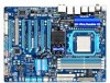
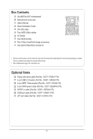
Box Contents GA-890FXA-UD7 motherboard Motherboard driver disk User's Manual Quick Installation Guide One IDE cable Four SATA package you obtain. The box contents are subject to change without notice. • The motherboard image is for reference only. Optional Items Floppy disk drive cable (Part No. - Gigabyte GA-890FXA-UD7 | Manual - Page 7
GA-890FXA-UD7 Motherboard Layout KB_MS_USB ATX_12V RCA_SPDIF USB_1394_ESATA_2 USB_1394_ESATA_1 CPU_FAN Socket AM3 USB_LAN2 USB30_LAN1 JMicron JMB362 AUDIO NEC D720200F1 F_AUDIO NB_FAN Realtek RTL8111D AMD 890FX Realtek RTL8111D CODEC GA-890FXA-UD7 SPDIF_I SPDIF_O CD_IN iTE IT8720 PCI - Gigabyte GA-890FXA-UD7 | Manual - Page 8
GA-890FXA-UD7 Motherboard Block Diagram 4 PCI Express x8 2 PCI Express x16 1 PCI Express x4 or PCIe CLK (100 MHz) PCI Express x8 x16 Bus Switch x4 x1 x1 2 USB 3.0/2.0 NEC D720200F1 JMicron JMB362 2 SATA 3Gb/s CPU CLK+/- (200 MHz) AM3 CPU DDR3 1866 (O.C.)/1333/1066 MHz (Note 1) Dual - Gigabyte GA-890FXA-UD7 | Manual - Page 9
manual and follow these procedures: • Prior to installation, do not remove or break motherboard com- ponents such as a motherboard, CPU or memory. If you do not have an system components as well as physical harm to the user. • If you are uncertain about any installation steps or have a problem - Gigabyte GA-890FXA-UD7 | Manual - Page 10
for AM3 processors: AMD Phenom™ II processor/ AMD Athlon™ II processor (Go to GIGABYTE's website for the latest CPU support list.) Hyper Transport Bus 5200 MT/s Chipset North Bridge: AMD 890FX South Bridge: AMD SB850 Memory 4 x 1.5V DDR3 DIMM sockets supporting up to 16 GB of system - Gigabyte GA-890FXA-UD7 | Manual - Page 11
floppy disk drive connector w 1 x IDE connector w 6 x SATA 6Gb/s connectors w 2 x SATA 3Gb/s connectors w 1 x CPU fan header w 2 x system fan headers w 1 x North Bridge fan header w 1 x power fan header w 1 x front panel header w 1 x front panel - Gigabyte GA-890FXA-UD7 | Manual - Page 12
Security (OEM version) Operating System w Support for Microsoft® Windows® 7/Vista/XP Form Factor w XL-ATX Form Factor; 32.5cm x 24.4cm (Note 1) Due to Windows 32-bit operating system limitation, when more than 4 GB of physical memory is installed, the actual memory size displayed will be - Gigabyte GA-890FXA-UD7 | Manual - Page 13
before you begin to install the CPU: • Make sure that the motherboard supports the CPU. (Go to GIGABYTE's website for the latest CPU support list.) • Always turn off the computer and unplug the power cord from the power outlet before installing the CPU to prevent hardware damage. • Locate the - Gigabyte GA-890FXA-UD7 | Manual - Page 14
below to correctly install the CPU into the motherboard CPU socket. • Before installing the CPU, make sure to turn off the computer and unplug the power cord from the power outlet to prevent damage to the CPU. • Do not force the CPU into the CPU socket. The CPU cannot fit in if oriented incorrectly - Gigabyte GA-890FXA-UD7 | Manual - Page 15
lock into place. (Refer to your CPU cooler installation manual for instructions on installing the cooler.) Step 5: Finally, attach the power connector of the CPU cooler to the CPU fan header (CPU_FAN) on the motherboard. Use extreme care when removing the CPU cooler because the thermal grease/tape - Gigabyte GA-890FXA-UD7 | Manual - Page 16
the Hybrid Silent-Pipe module: If you want to connect the front audio module from your chassis to the F_AUDIO connector on the motherboard, be sure to connect it before installing the Hybrid Silent-Pipe module to avoid interference. Tools needed: 1. A Philip's screwdriver 2. Thermal grease Hybrid - Gigabyte GA-890FXA-UD7 | Manual - Page 17
before you begin to install the memory: • Make sure that the motherboard supports the memory. It is recommended that memory of the same capacity, brand, speed, and chips be used. (Go to GIGABYTE's website for the latest supported memory speeds and memory modules) • Always turn off the computer - Gigabyte GA-890FXA-UD7 | Manual - Page 18
to install DDR3 DIMMs on this motherboard. Notch DDR3 DIMM A DDR3 memory module has a notch, so it can only fit in one direction. Follow the steps below to correctly install your memory modules in the memory sockets. Step 1: Note the orientation of the memory module. Spread the retaining clips at - Gigabyte GA-890FXA-UD7 | Manual - Page 19
supports the expansion card. Carefully read the manual that came with your expansion card. • Always turn off the computer and unplug the power cord from the power outlet before installing an expansion card to prevent hardware damage. PCI Express x16 Slot (PCIEX16_1/PCIEX16_2) PCI Express x16 - Gigabyte GA-890FXA-UD7 | Manual - Page 20
supports Windows XP, Windows Vista, and Windows 7 operating systems - The 3-Way/4-Way CrossFireX technology currently supports Windows Vista and Windows 7 operating systems only - A CrossFireX-supported motherboard with two/three/four PCI Express x16 cards. Refer to the manual that came with your - Gigabyte GA-890FXA-UD7 | Manual - Page 21
system by expanding the internal SATA port(s) to the chassis back panel. • Turn off your system install the SATA bracket: Step 1: Locate one free PCI slot and secure the SATA bracket to the chassis from the bracket to the SATA port on your motherboard. Step 3: Connect the power cable from the bracket - Gigabyte GA-890FXA-UD7 | Manual - Page 22
an external audio system that supports digital optical audio. Before using this feature, ensure that your audio system provides an optical connector, first remove the cable from your device and then remove it from the motherboard. • When removing the cable, pull it straight out from the connector. - Gigabyte GA-890FXA-UD7 | Manual - Page 23
USB 3.0/2.0 Port The USB 3.0 port supports the USB 3.0 specification and is compatible to the USB 2.0/1.1 specification MUST be connected to the default Mic in jack ( ). Refer to the instructions on setting up a 2/4/5.1/7.1-channel audio configuration in Chapter 5, "Configuring 2/4/5.1/7.1-Channel - Gigabyte GA-890FXA-UD7 | Manual - Page 24
devices. • After installing the device and before turning on the computer, make sure the device cable has been securely attached to the connector on the motherboard. Hardware Installation - 24 - - Gigabyte GA-890FXA-UD7 | Manual - Page 25
to all the components on the motherboard. Before connecting the power connector, first connector mainly supplies power to the CPU. If the 12V power connector is not provide the required power, the result can lead to an unstable or unbootable system. 8 4 5 1 ATX_12V ATX_12V: Pin No. 1 2 3 4 5 - Gigabyte GA-890FXA-UD7 | Manual - Page 26
motherboard supports CPU fan speed control, which requires the use of a CPU fan with fan speed control design. For optimum heat dissipation, it is recommended that a system in the correct orientation. Most fans are designed with color-coded power connector wires. A red power connector wire indicates - Gigabyte GA-890FXA-UD7 | Manual - Page 27
contact the local dealer. 34 33 2 1 8) IDE (IDE Connector) The IDE connector supports up to two IDE devices such as hard drives and optical drives. Before attaching the IDE for the IDE devices, read the instructions from the device manufacturers.) 40 39 2 1 - 27 - Hardware Installation - Gigabyte GA-890FXA-UD7 | Manual - Page 28
RXN 6 RXP 7 GND DEBUG PORT 10) GSATA2_6/7 (SATA 3Gb/s Connectors, Controlled by GIGABYTE SATA2) The SATA connectors conform to SATA 3Gb/s standard and are compatible with SATA 1.5Gb/s standards. Each SATA connector supports a single SATA device. The GIGABYTE SATA2 supports RAID 0, RAID 1, and - Gigabyte GA-890FXA-UD7 | Manual - Page 29
One single short beep will be heard if no problem is detected at system startup. If a problem is detected, the BIOS may issue beeps in different patterns to indicate the problem. Refer to Chapter 5, "Troubleshooting," for information about beep codes. • HD (Hard Drive Activity LED, Blue) Connects to - Gigabyte GA-890FXA-UD7 | Manual - Page 30
pin assignments of the motherboard header. Incorrect connection between the module connector and the motherboard header will make the device front panel audio header supports HD audio by default. If your chassis provides an AC'97 front panel audio module, refer to the instructions on how to activate - Gigabyte GA-890FXA-UD7 | Manual - Page 31
) This header supports digital S/PDIF Out and connects a S/PDIF digital audio cable (provided by expansion cards) for digital audio output from your motherboard to certain expansion audio cable, carefully read the manual for your expansion card. Pin No. Definition 1 SPDIFO 2 GND 1 - - Gigabyte GA-890FXA-UD7 | Manual - Page 32
) 9 10 1 2 3 USB DX- 4 USB DY- 5 USB DX+ 6 USB DY+ 7 GND 8 GND 9 No Pin 10 NC When the system is in S4/S5 mode, only the USB ports routed to the F_USB1 header can support the ON/OFF Charge function. • Do not plug the IEEE 1394 bracket (2x5-pin) cable into the USB - Gigabyte GA-890FXA-UD7 | Manual - Page 33
the jumper. Failure to do so may cause damage to the motherboard. • After system restart, go to BIOS Setup to load factory defaults (select Load Optimized Defaults) or manually configure the BIOS settings (refer to Chapter 2, "BIOS Setup," for BIOS configurations). - 33 - Hardware Installation - Gigabyte GA-890FXA-UD7 | Manual - Page 34
2 3 NSOUT 4 NDTR- 5 GND 6 NDSR- 7 NRTS- 8 NCTS- 9 NRI- 10 No Pin 21) BAT (Battery) The battery provides power to keep the values (such as BIOS configurations, date, and time information) in the CMOS when the computer is turned off. Replace the battery when the battery voltage drops to a low - Gigabyte GA-890FXA-UD7 | Manual - Page 35
24) PW_SW/ RST_SW/ CMOS_SW (Quick Buttons) This motherboard has 3 quick buttons: power button, clearing CMOS button system restart, go to BIOS Setup to load factory defaults (select Load Optimized Defaults) or manually configure the BIOS settings (refer to Chapter 2, "BIOS Setup," for BIOS - Gigabyte GA-890FXA-UD7 | Manual - Page 36
Hardware Installation - 36 - - Gigabyte GA-890FXA-UD7 | Manual - Page 37
it is recommended that you not flash the BIOS. To flash the BIOS, do it with caution. Inadequate BIOS flashing may result in system malfunction. • BIOS will emit a beep code during the POST. Refer to Chapter 5, "Troubleshooting," for the beep codes description. • It is recommended that you not alter - Gigabyte GA-890FXA-UD7 | Manual - Page 38
v6.00PG, An Energy Star Ally Copyright (C) 1984-2010, Award Software, Inc. Motherboard Model BIOS Version GA-890FXA-UD7 DC . . . . : BIOS Setup : XpressRecovery2 : Boot Menu : Qflash 03/24/2010-RD890-SB850-7A66DG03C-00 Function Keys Function Keys: : POST SCREEN Press - Gigabyte GA-890FXA-UD7 | Manual - Page 39
Save & Exit Setup Change CPU's Clock & Voltage F11: Save CMOS to BIOS F12: Load CMOS from BIOS BIOS Setup Program Function Keys . • When the system is not stable as usual, select the Load Optimized Defaults item to set your system to its defaults. • The BIOS Setup menus described in - Gigabyte GA-890FXA-UD7 | Manual - Page 40
the clock, frequency and voltages of your CPU, memory, etc. Standard CMOS Features Use this menu to configure the system time and date, hard drive types, floppy disk drive types, and the type of errors that stop the system boot, etc. Advanced BIOS Features Use this menu to configure the device - Gigabyte GA-890FXA-UD7 | Manual - Page 41
General Help F7: Optimized Defaults • Whether the system will work stably with the overclock/overvoltage settings you made is dependent on your overall system configurations. Incorrectly doing overclock/overvoltage may result in damage to CPU, chipset, or memory and reduce the useful life of these - Gigabyte GA-890FXA-UD7 | Manual - Page 42
Control Enables or disables the control of CPU host clock. Auto (default) allows the BIOS to automatically adjust the CPU host frequency. Manual allows the CPU Frequency (MHz) item below to be configurable. Note: If your system fails to boot after overclocking, please wait for 20 seconds to allow - Gigabyte GA-890FXA-UD7 | Manual - Page 43
Setup Utility-Copyright (C) 1984-2010 Award Software DRAM Configuration CPU Host Clock Control x CPU Frequency(MHz) Set Memory Clock x Memory Clock DCTs Mode DDR3 Timing Items x CAS# latency Fail-Safe Defaults - 43 - ESC: Exit F1: General Help F7: Optimized Defaults BIOS Setup - Gigabyte GA-890FXA-UD7 | Manual - Page 44
Tweaker(M.I.T.) main menu. DCTs Mode Allows you to set memory control mode. Ganged Sets memory control mode to single dual-channel. Unganged Sets memory control mode to two single-channel. (Default) DDR3 Timing Items Manual allows all DDR3 Timing items below to be configurable. Options - Gigabyte GA-890FXA-UD7 | Manual - Page 45
the system restarts. (Default: Skip DQS) CKE Power Down Mode Determines whether to set the memory to power down mode when the CKE pin is closed. (Default: Disabled) Memclock tri-stating Determines whether to enable memory clock tri-stating in CPU C3 or Alt VID mode. (Default: Disabled) - 45 - BIOS - Gigabyte GA-890FXA-UD7 | Manual - Page 46
whether to manually set the system voltages. Auto lets the BIOS automatically set the system voltages as required. Manual allows all voltage control items below to be configurable. (Default: Auto) CPU PLL Voltage Control Allows you to set the CPU PLL voltage. Normal Supplies the CPU PLL voltage - Gigabyte GA-890FXA-UD7 | Manual - Page 47
Floppy 3 Mode Support [1.44M, 3.5"] Memory [All, But Keyboard] 640K 1022M Item Help Menu Level Move Enter: Select F5: Previous Values +/-/PU/PD: Value F10: Save F6: Fail-Safe Defaults ESC: Exit F1: General Help F7: Optimized Defaults Date (mm:dd:yy) Sets the system BIOS Setup - Gigabyte GA-890FXA-UD7 | Manual - Page 48
2.88M/3.5". Floppy 3 Mode Support Allows you to specify whether system boot will not stop for a keyboard or a floppy disk drive error but it will stop for all other errors. Memory These fields are read-only and are determined by the BIOS POST. Base Memory Also called conventional memory - Gigabyte GA-890FXA-UD7 | Manual - Page 49
Award Software Advanced BIOS Features AMD C1E Support Virtualization AMD K8 Cool&Quiet control CPU Unlock (Note) CPU core Control x CPU core 2 (Note) x CPU core 3 (Note) } Hard Disk Boot Priority First Boot Device Second Boot Device Third Boot Device Password - Gigabyte GA-890FXA-UD7 | Manual - Page 50
list. Press to exit this menu when finished. First/Second/Third Boot Device Specifies the boot GIGABYTE Logo at system startup. Disabled displays normal POST message. (Default: Enabled) Backup BIOS Image to HDD Allows the system to copy the BIOS image file to the hard drive. If the system BIOS - Gigabyte GA-890FXA-UD7 | Manual - Page 51
SATA Type (AMD SB850, SATA3_0~SATA3_3 connectors) Configures the operating mode of the integrated SATA3_0~SATA3_3 connectors. Native IDE Allows the SATA controller to operate in Native IDE mode. (Default) Enable Native IDE mode if you wish to install operating systems that support Native - Gigabyte GA-890FXA-UD7 | Manual - Page 52
LAN1 Boot ROM } SMART LAN1 Onboard LAN2 Function Onboard LAN2 Boot ROM BIOS automatically configure this setting depending on the device being installed. (Default) X16 PCIEX16_1 operates at x16 become unavailable. Onboard GSATA controller (GIGABYTE SATA2 Chip, IDE and GSATA2_6 - Gigabyte GA-890FXA-UD7 | Manual - Page 53
LAN1/LAN2 Boot ROM Allows you to decide whether to activate the boot ROM integrated F7: Optimized Defaults This motherboard incorporates cable diagnostic feature no LAN cable is attached to the motherboard, the Status fields of all four ... If no cable problem is detected on the LAN cable connected to - Gigabyte GA-890FXA-UD7 | Manual - Page 54
it will operate at a normal speed of 10/100/1000 Mbps in Windows mode or when the LAN Boot ROM is activated. When a Cable Problem Occurs... If a cable problem occurs on a specified pair of wires, the Status field will show set to ECP or ECP+EPP mode. Options are: 3 (default), 1. BIOS Setup - 54 - - Gigabyte GA-890FXA-UD7 | Manual - Page 55
-up signal from the installed USB device. (Default: Enabled) Modem Ring Resume Allows the system to be awakened from an ACPI sleep state by a wake-up signal from a modem that supports wake-up function. (Default: Disabled) (Note) Supported on Windows 7/Vista operating system only. - 55 - BIOS Setup - Gigabyte GA-890FXA-UD7 | Manual - Page 56
a wake-up signal from a PCI or PCIe device. Note: To use this function, you need an ATX power supply providing at least 1A on the +5VSB lead. (Default: Enabled) HPET Support (Note) Enables or disables High Precision Event Timer (HPET) for Windows 7/Vista operating system. (Default: Enabled) Power On - Gigabyte GA-890FXA-UD7 | Manual - Page 57
-Copyright (C) 1984-2010 Award Software PC Health Status CPU Smart FAN Mode System Smart FAN Control [Auto] [Enabled] Item Help boot. (Default: Disabled) Case Opened Displays the detection status of the chassis intrusion detection device attached to the motherboard CI header. If the system - Gigabyte GA-890FXA-UD7 | Manual - Page 58
system voltages. Current System/CPU Temperature Displays current system/CPU temperature. Current CPU/SYSTEM/NB FAN Speed (RPM) Displays current CPU/system/North Bridge fan speed. CPU Warning Temperature Sets the warning threshold for CPU temperature. When CPU temperature exceeds the threshold, BIOS - Gigabyte GA-890FXA-UD7 | Manual - Page 59
this item and then press the key to load the safest BIOS default settings. In case system instability occurs, you may try to load Fail-Safe defaults, which are the safest and most stable BIOS settings for the motherboard. 2-10 Load Optimized Defaults CMOS Setup Utility-Copyright (C) 1984-2010 - Gigabyte GA-890FXA-UD7 | Manual - Page 60
you must enter the supervisor password (or user password) at system startup to continue system boot. In BIOS Setup, you must enter the supervisor password if you wish to make changes to BIOS settings. The user password only allows you to view the BIOS settings but not to make changes. To clear the - Gigabyte GA-890FXA-UD7 | Manual - Page 61
Setup PC Health Status Exit Without Saving ESC: Quit F8: Q-Flash Select Item F10: Save & Exit Setup Save Data to CMOS F11: Save CMOS to BIOS F12: Load CMOS from BIOS Press on this item and press the key. This saves the changes to the CMOS and exits the - Gigabyte GA-890FXA-UD7 | Manual - Page 62
BIOS Setup - 62 - - Gigabyte GA-890FXA-UD7 | Manual - Page 63
drivers are installed, follow the on-screen instructions to restart your system. You can install other applications included in the motherboard driver disk. • For USB 2.0 driver support under the Windows XP operating system, please install the Windows XP Service Pack 1 or later. After installing the - Gigabyte GA-890FXA-UD7 | Manual - Page 64
applications that GIGABYTE develops and some free software. You can click the Install button on the right of an item to install it. 3-3 Technical Manuals This page provides GIGABYTE's application guides, content descriptions for this driver disk, and the motherboard manuals. Drivers Installation - Gigabyte GA-890FXA-UD7 | Manual - Page 65
3-4 Contact For the detailed contact information of the GIGABYTE Taiwan headquarter or worldwide branch offices, click the URL on this page to link to the GIGABYTE website. 3-5 System This page provides the basic system information. - 65 - Drivers Installation - Gigabyte GA-890FXA-UD7 | Manual - Page 66
drivers, or applications, click the Download Center button to link to the GIGABYTE website. The latest version of the BIOS, drivers, or applications will be displayed. 3-7 New Utilities This page provides a quick link to GIGABYTE's lately developed utilities for users to install. You can click the - Gigabyte GA-890FXA-UD7 | Manual - Page 67
be restored using Xpress Recovery2. • USB hard drives are not supported. • Hard drives in RAID/AHCI mode are not supported. Installation and Configuration: Turn on your system to boot from the Windows Vista setup disk. A. Installing Windows Vista and Partitioning the Hard Drive Step 1: Click Drive - Gigabyte GA-890FXA-UD7 | Manual - Page 68
data) and begin the installation of the operating system. Step 4: After the operating system is installed, right-click the Computer icon on Recovery2 cannot save the backup file. B. Accessing Xpress Recovery2 1. Boot from the motherboard driver disk to access Xpress Recovery2 for the first time. - Gigabyte GA-890FXA-UD7 | Manual - Page 69
D. Using the Restore Function in Xpress Recovery2 Select RESTORE to restore the backup to your hard drive in case the system breaks down. The RESTORE option will not be present if no backup is created before. E. Removing the Backup Step 1: If you wish to remove the - Gigabyte GA-890FXA-UD7 | Manual - Page 70
Award Software, Inc. GA-890FXA-UD7 DC . . . . : BIOS Setup : XpressRecovery2 : Boot Menu : Qflash 03/24/2010-RD890-SB850-7A66DG03C-00 Because BIOS flashing is potentially risky, please do it with caution. Inadequate BIOS flashing may result in system malfunction. Unique Features - Gigabyte GA-890FXA-UD7 | Manual - Page 71
Move ESC:Reset F10:Power Off Total size : 0 Free size : 0 3. Select the BIOS update file and press . Make sure the BIOS update file matches your motherboard model. Step 2: The process of the system reading the BIOS file from the floppy disk is displayed on the screen. When the message - Gigabyte GA-890FXA-UD7 | Manual - Page 72
> to exit Q-Flash and reboot the system. As the system boots, you should see the new BIOS version is present on the POST screen. Step 5: During the POST, press to enter BIOS Setup. Select Load Optimized Defaults and press to load BIOS defaults. System will re-detect all peripheral - Gigabyte GA-890FXA-UD7 | Manual - Page 73
model. Follow the on-screen instructions to complete. If the BIOS update file for your motherboard is not present on the @BIOS server site, please manually download the BIOS update file from GIGABYTE's website and follow the instructions in "Update the BIOS without Using the Internet Update - Gigabyte GA-890FXA-UD7 | Manual - Page 74
6 GIGABYTE's EasyTune 6 is a simple and easy-to-use interface that allows users to fine-tune their system settings or do overclock/overvoltage in Windows environment. The user-friendly EasyTune 6 interface also includes tabbed pages for CPU and memory information, letting users read their system - Gigabyte GA-890FXA-UD7 | Manual - Page 75
The Easy Energy Saver Interface A. Meter Mode In Meter Mode, GIGABYTE Easy Energy Saver shows how much power they have saved in a above data is for reference only. Actual performance may vary depending on motherboard model. • CPU Power and Power Scores are for reference only. Actual results may vary - Gigabyte GA-890FXA-UD7 | Manual - Page 76
application only if you want to make any changes or completely close the application. (Note 1) Maximize system power saving with Dynamic CPU Frequency Function; system performance may be affected. (Note 2) 1: Normal Power Saving (default); 2: Advanced Power Saving; 3: Extreme Power Saving. (Note - Gigabyte GA-890FXA-UD7 | Manual - Page 77
on the same network, making full use of Internet resources. Directions for using Q-Share After installing Q-Share from the motherboard driver disk, go to Start>All Programs>GIGABYTE>Q-Share. exe to launch the Q-Share tool. Find the Q-Share icon to configure the data sharing settings. in the - Gigabyte GA-890FXA-UD7 | Manual - Page 78
drives (partitioned on NTFS file system) in Windows Vista. Instructions: In the main menu, click to copy and click the Copy button. The files/folders listed on the screen are read-only so you cannot edit their the backup will be performed on the next boot. We recommend that you preserve at least - Gigabyte GA-890FXA-UD7 | Manual - Page 79
Standby Suspend Disable Description Enters Power on Suspend mode Enters Suspend to RAM mode Disables this function The Bluetooth dongle included in the motherboard package(Note 2) allows you to wake up the system from Suspend to RAM mode without the need to press the power button first. (Note - Gigabyte GA-890FXA-UD7 | Manual - Page 80
net- work switch or router device supports the IEEE 802.3ad LACP standard. Please refer to your network switch or router device manual for further details. Select Realtek Ethernet Diagnostic Utility and click Install. Step 1: Insert the motherboard driver disk and select Application Software - Gigabyte GA-890FXA-UD7 | Manual - Page 81
BIOS Setup. C. Configure a RAID array in RAID BIOS. (Note 1) D. Make a floppy disk containing the SATA RAID/AHCI driver for Windows XP. (Note 2) E. Install the SATA RAID/AHCI driver (Note 2) and operating system • Windows Vista/XP setup disk. • Motherboard driver disk. 5-1-1 Configuring AMD SB850 - Gigabyte GA-890FXA-UD7 | Manual - Page 82
system BIOS Setup. Step 1: Turn on your computer and press to enter BIOS Setup 1). To enable support for RAID 5, set OnChip SATA RAID5 Support to Enabled. BIOS Setup. The BIOS Setup menus described in this section may differ from the exact settings for your motherboard. The actual BIOS - Gigabyte GA-890FXA-UD7 | Manual - Page 83
RAID set in RAID BIOS Enter the RAID BIOS setup utility to configure a RAID array. Skip this step and proceed with the installation of Windows operating system for a non-RAID configuration. Step 1: After the POST memory test begins and before the operating system boot begins, look for a message - Gigabyte GA-890FXA-UD7 | Manual - Page 84
Create Arrays Manually To create a new array, press to enter the LD View Menu window (Figure 4). To create an array, press to 1 [ LD Define Menu ] RAID Mode Drv RAID 0 0 Stripe Block: 64 KB Gigabyte Boundary: ON Fast Init: ON Cache Mode: WriteThru Port:ID 01:00 02:00 [ Drives - Gigabyte GA-890FXA-UD7 | Manual - Page 85
where you will see the newlycreated array. 9. Press to return to Main Menu and press again if you want to exit the RAID BIOS utility. - 85 - Appendix - Gigabyte GA-890FXA-UD7 | Manual - Page 86
View Drive Assignments The View Drive Assignments option in the Main Menu displays whether the attached hard drives are assigned to a disk array or are unassigned. Under the Assignment column, drives are labeled with their assigned disk array or shown as Free if unassigned. Option ROM Utility (c) - Gigabyte GA-890FXA-UD7 | Manual - Page 87
motherboard. See the table below for the SATA controllers and their corresponding SATA ports. Then connect the power connector from your power supply to the hard drive. B. Configuring SATA controller mode in BIOS Setup Make sure to configure the SATA controller mode correctly in system BIOS Setup - Gigabyte GA-890FXA-UD7 | Manual - Page 88
a RAID array in RAID BIOS Enter the RAID BIOS setup utility to configure a RAID array. Skip this step and proceed to the installation of Windows operating system for a non-RAID configuration. After the POST memory test begins and before the operating system boot begins, look for a message - Gigabyte GA-890FXA-UD7 | Manual - Page 89
Disk Drive item. Then the Create New RAID screen appears (Figure 4). Gigabyte Technology Corp. RAID Setup Utility v1.07.16G [ Create New RAID List ] [ Help ] Enter RAID Name Enter a string between 1 to 16 characters in length for the created RAID drive to be identified by system BIOS - Gigabyte GA-890FXA-UD7 | Manual - Page 90
Disks: After a RAID mode is selected, RAID BIOS automatically assigns the two hard drives installed as the Size: GRAID 0-Stripe Select Disk 128 KB 240 GB Gigabyte Technology Corp. RAID Setup Utility v1.07.16G [ Hard Disk Drive List ] Model Name } HDD0: ST3120026AS } HDD1: ST3120026AS - Gigabyte GA-890FXA-UD7 | Manual - Page 91
Main Menu block to move the selection bar to the RAID Disk Drive List block. Select the array and press . A small window displaying the array information will appear in the center of the screen (Figure 9). Gigabyte Technology Corp. RAID Setup Utility v1.07.16G [ Main Menu ] Create RAID Disk - Gigabyte GA-890FXA-UD7 | Manual - Page 92
RAID BIOS utility, Gigabyte Technology Corp. RAID Setup Utility v1.07.16G [ Hard Disk Drive List Window [hi]-Select ITEM Figure 10 [ENTER]-Action [ESC]-Exit Now, you may proceed to create the SATA RAID/AHCI driver diskette and the installation of the SATA RAID/ AHCI driver and operating system - Gigabyte GA-890FXA-UD7 | Manual - Page 93
to copy the driver in MS-DOS and Windows mode. In MS-DOS mode: Prepare a startup disk that has CD-ROM support and a blank formatted floppy disk. Steps: 1: Boot from the startup disk. 2: Remove the startup disk and insert the prepared floppy disk and the motherboard driver disk (here we as- sume that - Gigabyte GA-890FXA-UD7 | Manual - Page 94
the ATi SB850, select 3) ATi AHCI/RAID Driver for XP for Windows XP operating system. • For the GIGABYTE SATA2/JMicron JMB362, select 1) GIGABYTE GSATA driver for 32bit system for Windows XP 32-bit operating system. Your system will then automatically copy the driver files to the floppy disk. Press - Gigabyte GA-890FXA-UD7 | Manual - Page 95
SATA RAID/AHCI driver diskette and correct BIOS settings, you are ready to install Windows Vista/ XP onto your hard drive(s). The followings are examples of Windows XP and Vista installation. A. Installing Windows XP Step 1: Restart your system to boot from the Windows XP setup disk and press - Gigabyte GA-890FXA-UD7 | Manual - Page 96
to configure a SCSI Adapter for use with Windows, using a device support disk provided by an adapter manufacturer. Select the SCSI Adapter you want from the following list, or press ESC to return to the previous screen. RAID/AHCI Driver for GIGABYTE GBB36X Controller (x32) ENTER=Select F3 - Gigabyte GA-890FXA-UD7 | Manual - Page 97
the AMD SB850: Step 1: Restart your system to boot from the Windows Vista setup disk and perform standard OS installation steps. When a screen similar to that below appears (RAID hard drive will not be detected at this stage), select Load Driver (Figure 4). Step 2: Figure 4 Insert the motherboard - Gigabyte GA-890FXA-UD7 | Manual - Page 98
Step 3: When a screen as shown in Figure 6 appears, select AMD AHCI Compatible RAID Controller and click Next. Figure 6 Step 4: After the driver is loaded, the RAID drive will appear. Select the RAID drive and then click Next to continue the OS installation (Figure 7). Appendix Figure 7 - 98 - - Gigabyte GA-890FXA-UD7 | Manual - Page 99
1: Restart your system to boot from the Windows Vista setup disk and perform standard OS installation steps. When a screen similar to that below appears (RAID/AHCI hard drive(s) will not be detected at this stage), select Load Driver (Figure 8). Figure 8 Step 2: Insert the motherboard driver disk - Gigabyte GA-890FXA-UD7 | Manual - Page 100
Step 3: When a screen as shown in Figure 10 appears, select GIGABYTE GBB36X Controller and click Next. Figure 10 Step 4: After the driver is loaded, select the RAID/AHCI drive(s) where you want to install the operating system and then click Next to continue the OS installation (Figure 11). - Gigabyte GA-890FXA-UD7 | Manual - Page 101
drive is added to replace a failed drive to rebuild a RAID 1 array. For the AMD SB850: While in the operating system, make sure the chipset drivers have been installed from the motherboard driver disk. Then launch the AMD RAIDXpert from All Programs in the Start Menu. Step 1: Enter the login ID and - Gigabyte GA-890FXA-UD7 | Manual - Page 102
one. Use either the RAID setup utility or the GIGABYTE RAID CONFIGURER utility in the operating system to perform the rebuild. • Rebuilding with the RAID Disk Drive List ] Model Name RDD0: GRAID RAID Level 1-Mirror Capacity 120 GB Status Degraded Members(HDDx) 0? [fgTAB]-Switch Window [hi - Gigabyte GA-890FXA-UD7 | Manual - Page 103
• Rebuilding in the operating system Make sure the GIGABYTE SATA2/JMicron JMB362 SATA controller driver has been installed from the motherboard driver disk. Launch the GIGABYTE RAID CONFIGURER from All Programs in the Start menu. Step 1: In the GIGABYTE RAID CONFIGURER screen, right-click on the - Gigabyte GA-890FXA-UD7 | Manual - Page 104
jack and manually configure the jack for microphone functionality. • Audio signals will be present on both of the front and back panel audio connections simultaneously. If you want to mute the back panel audio (only supported when using an HD front panel audio module), refer to instructions on the - Gigabyte GA-890FXA-UD7 | Manual - Page 105
the type of device you connect. Then click OK. Step 3: On the Speakers screen, click the Speaker Configuration tab. In the Speaker Configuration list, select Stereo, Quadraphonic, 5.1 Speaker, or 7.1 Speaker according to the type of speaker configuration you wish to set up. Then the speaker setup is - Gigabyte GA-890FXA-UD7 | Manual - Page 106
S/PDIF In 1. Installing the S/PDIF In Cable: Step 1: First, attach the connector at the end of the cable to the SPDIF_I header on your motherboard. Step 2: Secure the metal bracket to the chassis back panel with a screw. 2. Configuring S/PDIF In: On the Digital Input screen, click the Default - Gigabyte GA-890FXA-UD7 | Manual - Page 107
B. S/PDIF Out The S/PDIF Out jacks can transmit audio signals to an external decoder for decoding to get the best audio quality. 1. Connecting a S/PDIF Out Cable: S/PDIF Coaxial Cable S/PDIF Optical Cable Connect a S/PDIF coaxial cable or a S/PDIF optical cable (either one) to an external decoder - Gigabyte GA-890FXA-UD7 | Manual - Page 108
environment . (Note) Install the Dolby GUI Software driver from the motherboard driver disk. Click the Start icon Programs, Dolby Control Center to example.) . Point to All 1. : Click Dolby Pro Logic IIx. The system will expand 2-channel audio for a 7.1-channel surround sound playback. 2. : - Gigabyte GA-890FXA-UD7 | Manual - Page 109
5-2-4 Configuring Microphone Recording Step 1: After installing the audio driver, the HD Audio Manager icon will appear in the notification area. Double-click the icon to access the HD Audio Manager. Step 2: Connect your microphone to the Mic in jack (pink) on the back panel or the Mic in jack (pink - Gigabyte GA-890FXA-UD7 | Manual - Page 110
Step 4: To raise the recording and playback volume for the microphone, click the Microphone Boost icon on the right of the Recording Volume slider and set the Microphone Boost level. Step 5: After completing the settings above, click Start, point to All Programs, point to Accessories, and then click - Gigabyte GA-890FXA-UD7 | Manual - Page 111
. Be sure to save the recorded audio file upon completion. B. Playing the Recorded Sound You can play your recording in a digital media player program that supports your audio file format. - 111 - Appendix - Gigabyte GA-890FXA-UD7 | Manual - Page 112
descriptions may help you identify possible computer problems. (For reference only.) 1 short: System boots successfully 1 long, 3 short: Keyboard error 2 short: CMOS setting error 1 long, 9 short: BIOS ROM error 1 long, 1 short: Memory or motherboard error Continuous long beeps: Graphics card - Gigabyte GA-890FXA-UD7 | Manual - Page 113
. Secure the CPU cooler No on the CPU. Connect the CPU cooler power cable to the motherboard. Yes The problem is verified and solved. Check if the memory is installed properly on the memory slot. No Correctly insert the memory into the memory socket. Yes The problem is verified and - Gigabyte GA-890FXA-UD7 | Manual - Page 114
"). Select "Save & Exit Setup" to save changes and exit BIOS Setup. The problem is verified and solved. Turn off the computer and connect the IDE/SATA devices. Check if the system can boot successfully. Yes Reinstall the operating system. Reinstall other devices one by one (install one device at - Gigabyte GA-890FXA-UD7 | Manual - Page 115
RAM - Program basic chipset registers Detect memory - Auto-detection of DRAM size, type and ECC Expand compressed BIOS code to DRAM Call chipset hook to copy BIOS back to E000 & F000 shadow RAM Expand the Xgroup codes flash R/W codes into the run time area in F000 for ESCD & DMI support Use walking - Gigabyte GA-890FXA-UD7 | Manual - Page 116
smaller one in case the cacheable ranges between each CPU are not identical Initialize USB Keyboard & Mouse Test all memory (clear all extended memory to 0) Clear password according to H/W jumper (optional) Display number of processors (multi-processor platform) 1. Display PnP logo 2. Early ISA PnP - Gigabyte GA-890FXA-UD7 | Manual - Page 117
stack back to CMOS Initialize ISA PnP boot devices 1. USB final Initialization 2. Switch screen back to text mode NET PC: Build SYSID structure 1. Assign IRQs to PCI devices 2. Set up ACPI table at top of the memory 1. Invoke all ISA adapter ROMs 2. Invoke all PCI ROMs (except VGA) 1. Enable/Disable - Gigabyte GA-890FXA-UD7 | Manual - Page 118
up speed 4. Chipset final initialization 5. Power management final initialization 6. Clear screen & display summary table 7. Boot BIOS support (popup menu) Update keyboard LED & typematic rate 1. Build MP table 2. Initialize power-saving (optional) 3. Set CMOS century to 20h or 19h 4. Load CMOS time - Gigabyte GA-890FXA-UD7 | Manual - Page 119
GIGABYTE. Our Commitment to Preserving the Environment In addition to high-efficiency performance, all GIGABYTE motherboards office, your household waste disposal service or where you purchased the Customer Care number listed in your product's user's manual and we will be glad to help you - Gigabyte GA-890FXA-UD7 | Manual - Page 120
Finally, we suggest that you practice other environmentally friendly actions by understanding and using the energy-saving features of this product (where applicable), recycling the inner and outer packaging (including shipping containers) this product was delivered in, and by disposing of or - Gigabyte GA-890FXA-UD7 | Manual - Page 121
- 121 - Appendix - Gigabyte GA-890FXA-UD7 | Manual - Page 122
Appendix - 122 - - Gigabyte GA-890FXA-UD7 | Manual - Page 123
- 123 - Appendix - Gigabyte GA-890FXA-UD7 | Manual - Page 124
Appendix - 124 - - Gigabyte GA-890FXA-UD7 | Manual - Page 125
- 125 - Appendix - Gigabyte GA-890FXA-UD7 | Manual - Page 126
Appendix - 126 - - Gigabyte GA-890FXA-UD7 | Manual - Page 127
231, Taiwan TEL: +886-2-8912-4000 FAX: +886-2-8912-4003 Tech. and Non-Tech. Support (Sales/Marketing) : http://ggts.gigabyte.com.tw WEB address (English): http://www.gigabyte.com.tw WEB address (Chinese): http://www.gigabyte.tw • G.B.T. INC. - U.S.A. TEL: +1-626-854-9338 FAX: +1-626-854-9339 Tech - Gigabyte GA-890FXA-UD7 | Manual - Page 128
.ro • Serbia WEB address : http://www.gigabyte.co.rs • Kazakhstan WEB address : http://www.gigabyte.kz You may go to the GIGABYTE website, select your language in the language list on the top right corner of the website. • GIGABYTE Global Service System To submit a technical or non-technical (Sales
-
 1
1 -
 2
2 -
 3
3 -
 4
4 -
 5
5 -
 6
6 -
 7
7 -
8
-
9
-
10
-
11
-
12
-
13
-
14
-
15
-
16
-
17
-
18
-
19
-
20
-
21
-
22
-
23
-
24
-
25
-
26
-
27
-
28
-
29
-
30
-
31
-
32
-
33
-
34
-
35
-
36
-
37
-
38
-
39
-
40
-
41
-
42
-
43
-
44
-
45
-
46
-
47
-
48
-
49
-
50
-
51
-
52
-
53
-
54
-
55
-
56
-
57
-
58
-
59
-
60
-
61
-
62
-
63
-
64
-
65
-
66
-
67
-
68
-
69
-
70
-
71
-
72
-
73
-
74
-
75
-
76
-
77
-
78
-
79
-
80
-
81
-
82
-
83
-
84
-
85
-
86
-
87
-
88
-
89
-
90
-
91
-
92
-
93
-
94
-
95
-
96
-
97
-
98
-
99
-
100
-
101
-
102
-
103
-
104
-
105
-
106
-
107
-
108
-
109
-
110
-
111
-
112
-
113
-
114
-
115
-
116
-
117
-
118
-
119
-
120
-
121
-
122
-
123
-
124
-
125
-
126
-
127
-
128
 |
 |

GA-890FXA-UD7
AM3 socket motherboard for
AMD Phenom
™
II processor/ AMD Athlon
™
II processor
User's Manual
Rev. 2001
12ME-890FXA7-2001R