Gigabyte GA-8AENXP-DW Manual
Gigabyte GA-8AENXP-DW Manual
 |
View all Gigabyte GA-8AENXP-DW manuals
Add to My Manuals
Save this manual to your list of manuals |
Gigabyte GA-8AENXP-DW manual content summary:
- Gigabyte GA-8AENXP-DW | Manual - Page 1
GA-8AENXP-DW Intel® Pentium® 4 LGA775 Processor Motherboard User's Manual Rev. 1001 12ME-8AENXPDW-1001 - Gigabyte GA-8AENXP-DW | Manual - Page 2
Jan. 15, 2005 Motherboard GA-8AENXP-DW Jan. 15, 2005 - Gigabyte GA-8AENXP-DW | Manual - Page 3
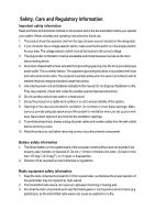
. The equipment operates safely when it is used in accordance with its marked electrical ratings and product usage instructions. 5. Use only the power cord and batteries indicated in this manual. Do not dispose of batteries in a fire. They may explode. Check with codes for possible special disposal - Gigabyte GA-8AENXP-DW | Manual - Page 4
, if not installed and used in accordance with the instructions, may cause harmful interference to radio communications. However, there that to which the receiver is connected. x Consult a dealer or experienced TV/radio technician for help. Properly shielded and grounded cables and connectors must be - Gigabyte GA-8AENXP-DW | Manual - Page 5
European Community Directive Conformance Statement: R&TTE Directive This wireless LAN card has been approved in accordance with Council Decision 99/5/EC on radio equipment and terminal telecommunication equipment (R&TTE Directive 1999/5/EC) as per * EN 60950 Safety of Information Technology - Gigabyte GA-8AENXP-DW | Manual - Page 6
. „ For detailed product information and specifications, please carefully read the "Product User Manual". „ For detailed information related to Gigabyte's unique features, please go to the "Technology Guide" section on Gigabyte's website to read or download the information you need. For more product - Gigabyte GA-8AENXP-DW | Manual - Page 7
Care and Regulatory Information 3 GA-8AENXP-DW Motherboard Layout 9 Block Diagram ...10 Chapter 1 Hardware Installation 13 1-1 Considerations Prior to Installation 13 1-2 Feature Summary 14 1-3 Installation of the CPU and Heatsink 16 1-3-1 Installation of the CPU 16 1-3-2 Installation of the - Gigabyte GA-8AENXP-DW | Manual - Page 8
Installation 55 3-1 Install Chipset Drivers 55 3-2 SoftwareApplications 56 3-3 Driver CD Information 56 3-4 Hardware Information 57 3-5 Contact Us ... 75 4-1-5 Configuring the Onboard Wireless LAN 87 4-1-6 2- / 4- / 6- / 8- Channel Audio Function Introduction 89 4-2 Troubleshooting 94 - 8 - - Gigabyte GA-8AENXP-DW | Manual - Page 9
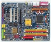
GA-8AENXP-DW Motherboard Layout KB MS SPDIF_O SPDIF_I VRM_CONN LGA775 IT8712F ATX IR GA-8AENXP-DW PWR_FAN LPT LAN2 LAN1 USB USB WDSI WSMA AUDIO1 Marvell 8053 AUDIO2 ATX_12V CPU_FAN AZALIA_FP Marvell 8053 NB_FAN Intel 925XE FDD IDE1 DDRII1 DDRII2 DDRII3 - Gigabyte GA-8AENXP-DW | Manual - Page 10
533/400MHz(Note) Intel 925XE DIMM Dual Channel Memory MCH MCHCLK (266/200/133MHz) 66MHz 33MHz 14.318MHz 48MHz Dual BIOS 4 Serial ATA Intel ICH6R Note) To use a DDRII 711 memory module on the motherboard, you must install an 1066MHz FSB processor and overclock in BIOS. To use a DDRII - Gigabyte GA-8AENXP-DW | Manual - Page 11
- 11 - - Gigabyte GA-8AENXP-DW | Manual - Page 12
- 12 - - Gigabyte GA-8AENXP-DW | Manual - Page 13
instructions below: 1. Please turn off the computer and unplug its power cord. 2. When handling the motherboard , avoid touching any metal leads or connectors. 3. It is best to wear an electrostatic discharge (ESD) cuff when handling electronic components (CPU motherboard problem manual - Gigabyte GA-8AENXP-DW | Manual - Page 14
system startup. (Note 2) To use a DDRII 711 memory module on the motherboard, you must install an 1066MHz FSB processor and overclock in BIOS. To use a DDRII 600 memory module on the motherboard, you must install an 800MHz FSB processor and overclock in BIOS. GA-8AENXP-DW Motherboard - 14 - - Gigabyte GA-8AENXP-DW | Manual - Page 15
Dual BIOS/Q-Flash/Multilanguage BIOS Supports U-Plus DPS Supports @BIOS Supports EasyTune 5 (Note) Over Voltage via BIOS (CPU/ FSB/DDR II/ PCI-E) Over Clock via BIOS (CPU/ DDR II/ PCI-E) ATX form factor; 30.5cm x 24.4cm (Note) EasyTune 5 functions may vary depending on different motherboards - Gigabyte GA-8AENXP-DW | Manual - Page 16
motherboard supports the CPU. 2. Please take note of the one indented corner of the CPU. If you install the CPU in the wrong direction, the CPU hardware specifications including the CPU, graphics card, memory, hard the CPU during installation.) GA-8AENXP-DW Motherboard - 16 - Fig. 4 Once the CPU is - Gigabyte GA-8AENXP-DW | Manual - Page 17
the CPU and make sure the push pins aim to the pin hole on the motherboard. Pressing down the push pins diagonally. Fig. 4 Please make sure the Male and Female push pin are joined closely. (for detailed installation instructions, please refer to the heatsink installation section of the user manual - Gigabyte GA-8AENXP-DW | Manual - Page 18
direction. The motherboard supports DDR II memory modules, whereby BIOS will automatically detect memory capacity and specifications. Memory modules are designed so that they can be inserted only in one direction. The memory capacity used can differ with each slot. GA-8AENXP-DW Motherboard - 18 - Gigabyte GA-8AENXP-DW | Manual - Page 19
the installation steps when you wish to remove the DIMM module. Dual Channel DDR II GA-8AENXP-DW supports the Dual Channel Technology. After operating the Dual Channel Technology, the bandwidth of Memory Bus will double. GA-8AENXP-DW includes 4 DIMM sockets, and each Channel has two DIMM sockets - Gigabyte GA-8AENXP-DW | Manual - Page 20
outlined below: 1. Read the related expansion card's instruction document before install the expansion card into the computer setup BIOS utility of expansion card from BIOS. 8. Install related driver from the operating system. Installing a PCI Express x 16 expansion GA-8AENXP-DW Motherboard - 20 - - Gigabyte GA-8AENXP-DW | Manual - Page 21
LED's are mounted on the U-Plus D.P.S. for intelligent indication of system loading. The U-Plus DPS can work in a Dual Power System: Parallel Mode-U-Plus DPS and motherboard CPU power can work simultaneously, providing a total of 8-phase power circuit. How to install U-Plus DPS? 1. The U-Plus DPS - Gigabyte GA-8AENXP-DW | Manual - Page 22
is capable of providing digital audio to external speakers or compressed provided Internet connection is Gigabit Ethernet (PCI Express Gigabit), supports USB controller. If your OS does not support USB controller, please contact OS vendor for possible patch or driver GA-8AENXP-DW Motherboard - 22 - - Gigabyte GA-8AENXP-DW | Manual - Page 23
/transmitting data. WSMA (Wireless LAN Antenna Port) Connect the dipolar antenna for the onboard wireless LAN. You can use audio software to configure 2-/4-/6-/8-channel audio functioning. 1-9 Connectors Introduction 13 19 2 5 7 6 8 15 22 9 240 16 21 13 12 10 18 17 11 8 14 1) ATX_12V - Gigabyte GA-8AENXP-DW | Manual - Page 24
Align the power connector with its proper location on the motherboard and connect tightly. The ATX_12V power connector mainly supplies power to the CPU. If the ATX_12V power connector is not connected, the -12V GND PS_ON(soft On/Off) GND GND GND -5V VCC VCC VCC GND GA-8AENXP-DW Motherboard - 24 - - Gigabyte GA-8AENXP-DW | Manual - Page 25
the power to the cooler to prevent system overheating and failure. Caution! Please remember to connect the power to the CPU fan to prevent CPU overheating and failure. 1 CPU_FAN 1 PWR_FAN 1 Pin No. 1 2 3 4 Definition GND +12V Sense Speed Control (Only for CPU_FAN) SYS_FAN 6) NB_FAN (Chip Fan - Gigabyte GA-8AENXP-DW | Manual - Page 26
while the other end of the cable connects to the FDD drive. The types of FDD drives supported are: 360KB, 720KB, 1.2MB, 1.44MB and 2.88MB. Please connect the red power connector to the instructions located on the IDE device). 40 39 2 1 IDE1 2 40 IDE2 1 39 GA-8AENXP-DW Motherboard - 26 - - Gigabyte GA-8AENXP-DW | Manual - Page 27
by SiI3114) Serial ATA can provide 150MB/s transfer rate. Please refer to the BIOS setting for the Serial ATA and install the proper driver in order to work properly. 1 7 SATA_SB (Controlled by ICH6R) 1 7 Pin No. 1 2 3 4 5 6 7 Definition GND TXP TXN GND RXN RXP GND SATA_SII (Controlled by - Gigabyte GA-8AENXP-DW | Manual - Page 28
. Please contact your nearest dealer for optional COMA cable. Pin No. Definition 1 NDCDA- 2 NSINA 2 10 3 NSOUTA 1 9 4 NDTRA- 5 GND 6 NDSRA- 7 NRTSA- 8 NCTSA- 9 NRIA- 10 No Pin GA-8AENXP-DW Motherboard - 28 - - Gigabyte GA-8AENXP-DW | Manual - Page 29
English 14) F_PANEL (Front Panel Jumper) Please connect the power LED, PC peaker, reset switch and power switch etc of your chassis frontpanel to the F_PANEL connector according to the pin assignment below. Speaker Connector Power Switch Message LED/ Power/ Sleep LED SPEAK- 20 19 SPEAK+ PWPW+ - Gigabyte GA-8AENXP-DW | Manual - Page 30
for this connector. To enable AC'97 Audio, from BIOS settings, set Front Panel Type under Integrated Peripherals to AC97. 16) CD_IN (CD In Connector) Connect CD-ROM or DVD-ROM audio out to the connector. Pin No. Definition 1 CD-L 2 GND 3 GND 1 4 CD-R GA-8AENXP-DW Motherboard - 30 - - Gigabyte GA-8AENXP-DW | Manual - Page 31
English 17) F_ USB1 / F_USB2 (Front USB Connector) Be careful with the polarity of the front USB connector. Check the pin assignment carefully while you connect the front USB cable, incorrect connection between the cable and connector will make the device unable to work or even damage it. For - Gigabyte GA-8AENXP-DW | Manual - Page 32
this jumper. To clear CMOS, temporarily short 1-2 pin. Default doesn't include the "Shunter" to prevent from improper use this jumper. Open: Normal 1 Short: Clear CMOS 1 GA-8AENXP-DW Motherboard - 32 - - Gigabyte GA-8AENXP-DW | Manual - Page 33
is incorrectly replaced. Replace only with the same or equivalent type recommended by the manufacturer. Dispose of used batteries according to the manufacturer's instructions. If you want to erase CMOS... 1. Turn OFF the computer and unplug the power cord. 2. Remove the battery, wait for 30 second - Gigabyte GA-8AENXP-DW | Manual - Page 34
English GA-8AENXP-DW Motherboard - 34 - - Gigabyte GA-8AENXP-DW | Manual - Page 35
of the motherboard. When the power is turned off, the battery on the motherboard supplies the you wish to upgrade to a new BIOS, either GIGABYTE's Q-Flash or @BIOS utility can be used. Q-Flash table Load the Optimized Defaults Dual BIOS/Q-Flash utility System Information - Gigabyte GA-8AENXP-DW | Manual - Page 36
Supervisor Password Set User Password Save & Exit Setup Exit Without Saving F8: Dual BIOS/Q-Flash F10: Save & Exit Setup Time, Date, Hard Disk This setup page is control CPU clock and frequency ratio. „ Select Language This setup page is to select multi languages. GA-8AENXP-DW Motherboard - 36 - - Gigabyte GA-8AENXP-DW | Manual - Page 37
English „ Load Fail-Safe Defaults Fail-Safe Defaults indicates the value of the system parameters which the system would be in safe configuration. „ Load Optimized Defaults Optimized Defaults indicates the value of the system parameters which the system would be in best performance configuration. „ - Gigabyte GA-8AENXP-DW | Manual - Page 38
] [None] Change the day, month, year Drive A Drive B Floppy 3 Mode Support Halt On [1.44M, 3.5"] [None] [Disabled] [All, But Keyboard] step and allow for faster system start up. • Manual User can manually input the correct settings. Access Mode Use this to GA-8AENXP-DW Motherboard - 38 - - Gigabyte GA-8AENXP-DW | Manual - Page 39
3.5 inch double-sided drive; 2.88M byte capacity. Floppy 3 Mode Support (for Japan Area) Disabled Drive A Normal Floppy Drive. (Default motherboard. Extended Memory The BIOS determines how much extended memory is present during the POST. This is the amount of memory located above 1 MB in the CPU - Gigabyte GA-8AENXP-DW | Manual - Page 40
CPU Enhanced Halt (C1E) (Note) CPU Thermal Monitor 2(TM2) (Note) [Press Enter] [Floppy] [Hard Disk] [CDROM] [SCSI Hard Disk Boot Priority Select boot sequence for onboard(or add-on cards) SCSI, RAID, etc. Use < > or < > to select a device, supports this function. GA-8AENXP-DW Motherboard - 40 - - Gigabyte GA-8AENXP-DW | Manual - Page 41
select onboard RAID or PCI SCSI boot ROM order if the boot ROM of your device cannot be auto initiated. SCSI Set boot ROM order to SCSI devices.. working for operating system with multi processors mode supported. (Default value) Disables CPU Hyper Threading. Limit CPUID Max. to 3 Enabled - Gigabyte GA-8AENXP-DW | Manual - Page 42
[Disabled] [Disabled] [Auto] [HD Audio] [Enabled] [Enabled] [Enabled] [RAID] [Enabled] [Enabled] [Enabled] Item RAID / AHCI Mode RAID Select onboard Serial ATA function as RAID. (Default value) AHCI Support motherboard; 2 for SATA and the other for PATA IDE. GA-8AENXP-DW Motherboard - 42 - - Gigabyte GA-8AENXP-DW | Manual - Page 43
SATA mode to Enhanced, the motherboard allows up to 6 HDDs to support. (Default value) USB Mouse Support Enabled Enable USB mouse support. Disabled Disable USB mouse support. (Default value) Azalia Codec Auto Disabled Auto detect Azalia audio function. (Default value) Disable Azalia audio - Gigabyte GA-8AENXP-DW | Manual - Page 44
Set onboard H/W SATA function as RAID. (Default value) BASE Set onboard H/W SATA function as BASE(ATA). Onboard Promise SATA Enabled Disabled Enable onboard you to select IR mode. Half IR Function Duplex Half. (Default value) Full IR Function Duplex Full. GA-8AENXP-DW Motherboard - 44 - - Gigabyte GA-8AENXP-DW | Manual - Page 45
English Onboard Parallel Port Disabled Disable onboard LPT port. 378/IRQ7 278/IRQ5 Enable onboard LPT port and address is 378/IRQ7. (Default value) Enable onboard LPT port and address is 278/IRQ5. 3BC/IRQ7 Enable onboard LPT port and address is 3BC/IRQ7. Parallel Port Mode SPP Using - Gigabyte GA-8AENXP-DW | Manual - Page 46
) : (0~59) Power On By Mouse Disabled Disabled this function. (Default value) Double Click Double click on PS/2 mouse left button to power on the system. GA-8AENXP-DW Motherboard - 46 - - Gigabyte GA-8AENXP-DW | Manual - Page 47
English Power On By Keyboard Password Enter from 1 to 5 characters to set the Keyboard Power On Password. Disabled Keyboard 98 Disabled this function. (Default value) If your keyboard have "POWER Key" button, you can press the key to power on the system. KB Power ON Password When "Power On - Gigabyte GA-8AENXP-DW | Manual - Page 48
CPU temperature at 80oC / 176oF. 90oC / 194oF Monitor CPU temperature at 90oC / 194oF. Disabled Disable this function. (Default value) CPU/POWER/SYSTEM FAN Fail Warning Disabled Fan warning function disable. (Default value) Enabled Fan warning function enable. GA-8AENXP-DW Motherboard - Gigabyte GA-8AENXP-DW | Manual - Page 49
between 20 and 65 degrees Celsius, the CPU fan speed will change depending on the actual CPU temperature. c. When the CPU temperature is lower than 20 degrees Celsius, CPU fan will stop spinning. CPU Smart FAN Mode This option is available only when CPU Smart FAN Control is enabled. Auto BIOS - Gigabyte GA-8AENXP-DW | Manual - Page 50
by CPU Turbo loading. Set C.I.A.2 to Turbo. Automatically increase CPU frequency(15,17%) by CPU Full Thrust loading. Set C.I.A.2 to Full Thrust. Automatically increase CPU frequency(17%,19%) by CPU loading. Warning: Stability is highly dependent on system components. GA-8AENXP-DW Motherboard - Gigabyte GA-8AENXP-DW | Manual - Page 51
. (Default value) Memory Frequency (Mhz) The values depend on CPU Host Frequency(Mhz) and Memory Frequency For setting. DIMM OverVoltage Control to +0.3V. (Note) To use a DDRII 711 memory module on the motherboard, you must install a 1066MHz FSB processor and set Memory Frequency For to 2.66. - Gigabyte GA-8AENXP-DW | Manual - Page 52
Setup ` MB Intelligent Tweaker(M.I.T.) Exit Without Saving Esc: Quit F8: Dual BIOS/Q-Flash F10: Save & Exit Setup Load Fail-Safe Defaults Fail-Safe defaults contain the most appropriate values of the system parameters that allow minimum system performance. GA-8AENXP-DW Motherboard - 52 - - Gigabyte GA-8AENXP-DW | Manual - Page 53
Select Language Load Fail-Safe Defaults Load Optimized Defaults Set Supervisor Password Set User Password Save & Exit Setup Exit Without Saving F8: Dual BIOS/Q-Flash F10: Save & Exit Setup Change/Set/Disable Password Selecting this field loads the factory defaults for BIOS and Chipset Features - Gigabyte GA-8AENXP-DW | Manual - Page 54
` PC Health Status Save & Exit Setup ` MB Intelligent Tweaker(M.I.T.) Exit Without Saving F8: Dual BIOS/Q-Flash F10: Save & Exit Setup Abandon all Data Type "Y" will quit the Setup Utility without saving to RTC CMOS. Type "N" will return to Setup Utility. GA-8AENXP-DW Motherboard - 54 - - Gigabyte GA-8AENXP-DW | Manual - Page 55
Installation Pictures below are shown in Windows XP. Insert the driver CD-title that came with your motherboard into your CD-ROM drive, the driver CD-title will auto start and show the installation guide. If not, please double click the CD-ROM device icon in "My computer", and execute the Run - Gigabyte GA-8AENXP-DW | Manual - Page 56
Applications This page displays all the tools that Gigabyte developed and some free software, you can choose anyone you want and press "install" to install them. 3-3 Driver CD Information This page lists the contents of software and drivers in this CD-title. GA-8AENXP-DW Motherboard - 56 - - Gigabyte GA-8AENXP-DW | Manual - Page 57
English 3-4 Hardware Information This page lists all device you have for this motherboard. 3-5 Contact Us Please see the last page for details. - 57 - Drivers Installation - Gigabyte GA-8AENXP-DW | Manual - Page 58
English GA-8AENXP-DW Motherboard - 58 - - Gigabyte GA-8AENXP-DW | Manual - Page 59
as well as displaying a detailed list of all new drivers with the option for download. C.O.M. (Corporate Online Management) A web-based system management tool that allows system hardware information such as CPU, memory, graphics card, etc. to be monitored and controlled via the Internet - Gigabyte GA-8AENXP-DW | Manual - Page 60
Easy and Advance Mode Display panel of CPU frequency Shows the current functions status Log on to GIGABYTE website Display EasyTuneTM 5 Help file Quit or Minimize EasyTuneTM 5 software (Note) EasyTune 5 functions may vary depending on different motherboards. GA-8AENXP-DW Motherboard - 60 - - Gigabyte GA-8AENXP-DW | Manual - Page 61
OS 4. Must be used with an IDE hard disk supporting HPA 5. The first partition must be set as the set to boot from CD-ROM. Insert the provided driver CD into your CD drive, then save and exit CD: Xpress Recovery V1.0 (C) Copy Right 2003. GIGABYTE Technology CO. , Ltd. 1. Execute Backup Utility 2. - Gigabyte GA-8AENXP-DW | Manual - Page 62
/2002-I845GE-6A69YG01C-00 F9 For Xpress Recovery Xpress Recovery V1.0 (C) Copy Right 2003. GIGABYTE Technology CO. , Ltd. 1. Execute Backup Utility 2. Execute Restore Utility 3. Remove Backup after OS and all required driver and software installations are complete. GA-8AENXP-DW Motherboard - 62 - - Gigabyte GA-8AENXP-DW | Manual - Page 63
Esc to Exit The backup utility will automatically scan your system and back up data as a backup image in your hard drive. Not all systems support access to Xpress Recovery by pressing the F9 key during computer power on. If this is the case, please use the boot from CD-ROM - Gigabyte GA-8AENXP-DW | Manual - Page 64
PC will still be able to run stably as if nothing has happened in your BIOS. B. How to use Dual BIOS and Q-Flash Utility? a. After power on the computer, pressing immediately during POST (Power On Self PgUp: Modify : Move ESC: Reset 512K 512K F10: Power Off GA-8AENXP-DW Motherboard - 64 - - Gigabyte GA-8AENXP-DW | Manual - Page 65
Status 2: If the ROM BIOS on peripherals cards(ex. SCSI Cards, LAN Cards,..) emits signals torequest restart of the system , and the system will pause and wait for the user's instruction. If Auto Recovery :Disable, it will show - Gigabyte GA-8AENXP-DW | Manual - Page 66
Dual BIOS Motherboards. Some of Gigabyte motherboards are equipped with dual BIOS. In the BIOS menu of the motherboards supporting Q-Flash and Dual BIOS, the Q-Flash utility and Dual SETUP / Dual BIOS / Q-Flash / F9 For Xpress Recovery 08/07/2003-i875P-6A79BG03C-00 GA-8AENXP-DW Motherboard - 66 - - Gigabyte GA-8AENXP-DW | Manual - Page 67
Advanced BIOS Features Integrated Peripherals Power Management Setup PnP/PCI Configurations PC Health Status MB Intelligent Tweaker(M.I.T.) ESC: Quit F8: Dual BIOS/Q-Flash Select Language Load Fail-Safe Defaults Load Optimized Defaults Set Supervisor Password Set User Password Save & Exit Setup - Gigabyte GA-8AENXP-DW | Manual - Page 68
, 8KNXPU.Fba, is listed. Please confirm again you have the correct BIOS file for your motherboard. Dual BIOS Utility Boot From Main Bios Main ROM Type/Size SST 49LF004A Backup ROM Type/Size SST confirmation dialog box asking you "Are you sure to update BIOS?" GA-8AENXP-DW Motherboard - 68 - - Gigabyte GA-8AENXP-DW | Manual - Page 69
out the floppy disk when it begins flashing BIOS. 4. Press any keys to return to the Q-Flash menu when the BIOS updating procedure is completed. Dual BIOS Utility Boot From Main Bios Main ROM Type/Size SST 49LF004A Backup ROM Type/Size SST 49LF004A 512K 512K Wide Range Protection Disable Boot - Gigabyte GA-8AENXP-DW | Manual - Page 70
Dual BIOS/Q-Flash F3: Change Language F10: Save & Exit Setup Time, Date, Hard Disk Type... Press Y on your keyboard to save and exit. Part Two: Updating BIOS with Q-FlashTM Utility on Single-BIOS Motherboards. This part guides users of single-BIOS motherboards ... GA-8AENXP-DW Motherboard - 70 - - Gigabyte GA-8AENXP-DW | Manual - Page 71
BIOS using the Q-Flash utility. As described in the "Before you begin" section above, you must prepare a floppy disk having the BIOS file for your motherboard and insert it to your computer. If you have already put the floppy disk into your system and have entered the Q-Flash utility, please follow - Gigabyte GA-8AENXP-DW | Manual - Page 72
-Safe Defaults". See how to Load BIOS Fail-Safe Defaults, please kindly refer to Step 6 to 7 in Part One. Congratulation!! You have updated BIOS successfully!! GA-8AENXP-DW Motherboard - 72 - - Gigabyte GA-8AENXP-DW | Manual - Page 73
Fig 2. Installation complete and run @BIOS Click Sart/ Programs/ GIGABYTE/@BIOS Select @BIOS item than click Install Fig 3. The @ Select @BIOSTM sever d. Select the exact model name on your motherboard e. System will automatically download and update the BIOS. II. instruction. - 73 - Appendix - Gigabyte GA-8AENXP-DW | Manual - Page 74
to save the current BIOS version. IV. Check out supported motherboard and Flash ROM: In the very beginning, there is Gigabyte's web site for downloading and updating it according to method II. IV. Please note that any interruption during updating will cause system unbooted GA-8AENXP-DW Motherboard - Gigabyte GA-8AENXP-DW | Manual - Page 75
performance levels, security levels and implementation costs. The RAID levels which the Intel® ICH6R chipset supports are RAID 0 and RAID 1. The RAID levels which the Promise PDC20779 chip supports are RAID 0 and RAID 1. RAID 0 (Striping) RAID 0 reads and writes sectors of data interleaved between - Gigabyte GA-8AENXP-DW | Manual - Page 76
to Non-RAID 4. Exit RAID Volumes : None Defined. [ DISK/VOLUME INFORMATION ] Physical Disks : Port Driver Model 0 ST3120026AS 1 ST3120026AS Serial # 3JT354CP 3JT329JX Size Type/Status(Vol ID) 111.7GB Non-RAID Disk 111.7GB Non-RAID Disk [ ]-Select GA-8AENXP-DW Motherboard [ESC]-Exit - Gigabyte GA-8AENXP-DW | Manual - Page 77
128KB 223.5 GB Create Volume [ HELP ] Enter a string between 1 and 16 characters in length that can be used to uniquely identify the RAID volume. This name is case sensitive and can not contain special characters. [ ]-Change [TAB]-Next [ESC]-Previous Menu [ENTER]-Select After entering the - Gigabyte GA-8AENXP-DW | Manual - Page 78
Capacity : RAID_Volume0 RAID0(Stripe) Select Disks 128KB 223.5 GB Create Volume [ HELP ] Choose the RAID level best suited to your usage model. The following are typical values: 16KB - Best for to enter Create Volume after setting disk capacity. [ENTER]-Select GA-8AENXP-DW Motherboard - 78 - - Gigabyte GA-8AENXP-DW | Manual - Page 79
Intel Corporation. All Rights Reversed. [ CREATE VOLUME MENU ] Name : RAID Level : Disks : Strip Size : Capacity : RAID_Volume0 RAID0(Stripe) Select Please press Y to complete the set-up of RAID. Intel(R) Application Accelerator RAID Option ROM v4.0.6180 Copyright(C) 2003-04 Intel Corporation. - Gigabyte GA-8AENXP-DW | Manual - Page 80
128KB Size Status 223.5GB Normal Bootable Yes Physical Disks : Port Driver Model 0 ST3120026AS 1 ST3120026AS Serial # 3JT354CP 3JT329JX Size Type/Status(Vol ID) 111.7GB Member Disk(0) 111.7GB Member Disk(0) [ ]-Select [ESC]-Exit [ENTER]-Select Menu GA-8AENXP-DW Motherboard - 80 - - Gigabyte GA-8AENXP-DW | Manual - Page 81
Utility or Press [ESC] to continue booting Press + . The Promise RAID Utility window appears (as Figure below). FastBuild (tm) 2.03 (c) 2003-2005 , press . Promise recommends this option for most users. To manually create an array, press to enter the Define Array window. - Gigabyte GA-8AENXP-DW | Manual - Page 82
(RAID 0), FastTrak assigns two drives to a single Striped array. If you want a one-drive array or you want to specify block size, please go to the Define Array windows. Security: Under the Security setting (RAID 1), FastTrak assigns two drives to a single Mirrored array. GA-8AENXP-DW Motherboard - Gigabyte GA-8AENXP-DW | Manual - Page 83
Main Menu allows users to begin the process of manually defining the drive elements and RAID levels for one or multiple disk arrays attached to Array Menu] Logical Disk No RAID Mode Total Drv Status Logical Disk 1 Stripe 0 Functional Stripe Block: 64KB Gigabyte Rounding: OFF Channel:ID 1: - Gigabyte GA-8AENXP-DW | Manual - Page 84
RAID 0) arrays, you can manually select the stripe block size. Press the Space bar to scroll through choices from 32 to 128KB. The default is 64KB. Gigabyte Rounding: The Gigabyte Rounding feature is designed for Mirrored (RAID array or shown as Spare if unassigned. GA-8AENXP-DW Motherboard - 84 - - Gigabyte GA-8AENXP-DW | Manual - Page 85
03 (c) 2003-2005 Promise Technology, Inc. [ View Array Definition Menu] Logical Disk No RAID Mode Total Drv Capacity (MB) Status Logical Disk 1 Stripe 2 240068 Functional Stripe Block: 64KB Gigabyte Rounding: OFF Channel:ID 1:SATA 2:SATA [ Drives Assignments] ] Drive Model ST3120026AS - Gigabyte GA-8AENXP-DW | Manual - Page 86
time you add a new hard drive to a RAID array, the RAID driver will have to be installed under Windows once for that hard drive. After that, the driver will not have to be installed.) Note: In the menu list, Intel Application Accelerator 4.0 is Intel ICH6R chipset. GA-8AENXP-DW Motherboard - 86 - - Gigabyte GA-8AENXP-DW | Manual - Page 87
designed to make installing and setting up the Onboard Wireless LAN feature easier. Before we begin, if your PC is using other third party wireless drivers, we suggest you disable them now. Now lets get started! Configuring the Onboard Wireless LAN A. Insert your Setup CD into your Desktop PC's CD - Gigabyte GA-8AENXP-DW | Manual - Page 88
of your Wireless LAN feature is complete! For more information about your onboard Wireless LAN and the Wireless Utility, please download the Wireless LAN user manual for the GA-8AENXP-DW motherboard from www.gigabyte.com.tw. GA-8AENXP-DW Motherboard - 88 - - Gigabyte GA-8AENXP-DW | Manual - Page 89
you use the speaker with amplifier to acquire the best sound effect if the stereo output is applied. STEP 1: Connect the stereo speakers or earphone to "Line Out". Line Out STEP 2 : Following installation of the audio driver, you find a Sound Effect icon on the lower right hand taskbar. Click the - Gigabyte GA-8AENXP-DW | Manual - Page 90
of the audio driver, you find a Sound Effect icon on the lower right hand taskbar. Click the icon to select the function. STEP 3: Click "Speaker Configuration" then click on the left selection bar and select "4CH Speaker" to complete 4 channel audio configuration. GA-8AENXP-DW Motherboard - 90 - Gigabyte GA-8AENXP-DW | Manual - Page 91
channels to "Rear Speaker Out", and the Center/Subwoofer channels to "Center/Subwoofer Speaker Out". STEP 2 : Following installation of the audio driver, you find a Sound Effect icon on the lower right hand taskbar. Click the icon to select the function. STEP 3: Click "Speaker Configuration" then - Gigabyte GA-8AENXP-DW | Manual - Page 92
installation of the audio driver, you find a Sound Effect icon on audio configuration. Sound Effect Configuration: At the sound effect menu, users can adjust sound option settings as desired. Front Speaker Out Rear Speaker Out Center/Subwoofer Speaker Out Side Speaker Out GA-8AENXP-DW Motherboard - Gigabyte GA-8AENXP-DW | Manual - Page 93
before to enable Jack-Sensing support for Windows 2000. After you install an audio device, a screen of a list would pop up from the audio software for you to choose jack following the arrow instruction. The correct icon for audio device will be displayed after the reinstallation. - 93 - Appendix - Gigabyte GA-8AENXP-DW | Manual - Page 94
manual and check whether you have connected any cable that is not provided with the motherboard package to the USB Over Current pin in the Front USB Panel. If the cable is your own cable, please remove it from this pin and do not connect any of your own cables to it. GA-8AENXP-DW Motherboard - Gigabyte GA-8AENXP-DW | Manual - Page 95
computer after system boots up. What do these beeps usually stand for? Answer: The beep codes below may help you identify the possible computer problems. However, they are only for reference purposes. The situations might differ from case to case. AMI BIOS Beep Codes *Computer gives 1 short beep - Gigabyte GA-8AENXP-DW | Manual - Page 96
English GA-8AENXP-DW Motherboard - 96 - - Gigabyte GA-8AENXP-DW | Manual - Page 97
- 97 - Appendix English - Gigabyte GA-8AENXP-DW | Manual - Page 98
English GA-8AENXP-DW Motherboard - 98 - - Gigabyte GA-8AENXP-DW | Manual - Page 99
- 99 - Appendix English - Gigabyte GA-8AENXP-DW | Manual - Page 100
English GA-8AENXP-DW Motherboard - 100 - - Gigabyte GA-8AENXP-DW | Manual - Page 101
- 101 - Appendix English - Gigabyte GA-8AENXP-DW | Manual - Page 102
English GA-8AENXP-DW Motherboard - 102 - - Gigabyte GA-8AENXP-DW | Manual - Page 103
Milton Keynes, MK1 1DR, UK, England TEL: +44-1908-362700 FAX: +44-1908-362709 Tech. Support : http://uk.giga-byte.com/TechSupport/ServiceCenter.htm Non-Tech. Support(Sales/Marketing) : http://ggts.gigabyte.com.tw/nontech.asp WEB address : http://uk.giga-byte.com The Netherlands GIGA-BYTE TECHNOLOGY - Gigabyte GA-8AENXP-DW | Manual - Page 104
://www.gigabyte.ru Poland Representative Office Of Giga-Byte Technology Co., Ltd. POLAND Tech. Support : http://tw.giga-byte.com/TechSupport/ServiceCenter.htm Non-Tech. Support(Sales/Marketing) : http://ggts.gigabyte.com.tw/nontech.asp WEB address : http://www.gigabyte.pl GA-8AENXP-DW Motherboard
-
 1
1 -
 2
2 -
 3
3 -
 4
4 -
 5
5 -
 6
6 -
 7
7 -
8
-
9
-
10
-
11
-
12
-
13
-
14
-
15
-
16
-
17
-
18
-
19
-
20
-
21
-
22
-
23
-
24
-
25
-
26
-
27
-
28
-
29
-
30
-
31
-
32
-
33
-
34
-
35
-
36
-
37
-
38
-
39
-
40
-
41
-
42
-
43
-
44
-
45
-
46
-
47
-
48
-
49
-
50
-
51
-
52
-
53
-
54
-
55
-
56
-
57
-
58
-
59
-
60
-
61
-
62
-
63
-
64
-
65
-
66
-
67
-
68
-
69
-
70
-
71
-
72
-
73
-
74
-
75
-
76
-
77
-
78
-
79
-
80
-
81
-
82
-
83
-
84
-
85
-
86
-
87
-
88
-
89
-
90
-
91
-
92
-
93
-
94
-
95
-
96
-
97
-
98
-
99
-
100
-
101
-
102
-
103
-
104
 |
 |

GA-8AENXP-DW
Intel
®
Pentium
®
4 LGA775 Processor Motherboard
User's Manual
Rev. 1001
12ME-8AENXPDW-1001