Gigabyte GA-8I848P775-G Manual
Gigabyte GA-8I848P775-G Manual
 |
View all Gigabyte GA-8I848P775-G manuals
Add to My Manuals
Save this manual to your list of manuals |
Gigabyte GA-8I848P775-G manual content summary:
- Gigabyte GA-8I848P775-G | Manual - Page 1
GA-8I848P775-G Intel® Pentium® 4 LGA775 Processor Motherboard User's Manual Rev. 1003 12ME-8I848PTG-1003 * The WEEE marking on the product indicates this product must not be disposed of with user's other household waste and must - Gigabyte GA-8I848P775-G | Manual - Page 2
Motherboard GA-8I848P775-G Mar. 11, 2005 Motherboard GA-8I848P775-G Mar. 11, 2005 - Gigabyte GA-8I848P775-G | Manual - Page 3
the product. „ For detailed product information and specifications, please carefully read the "Product User Manual". „ For detailed information related to Gigabyte's unique features, please go to "Technology Guide" section on Gigabyte's website to read or download the information you need. For more - Gigabyte GA-8I848P775-G | Manual - Page 4
Table of Contents GA-8I848P775-G Motherboard Layout 6 Block Diagram ...7 Chapter 1 Hardware Installation 9 1-1 Considerations Prior to Installation 9 1-2 Feature Summary 10 1-3 Installation of the CPU and Heatsink 12 1-3-1 Installation of the CPU 12 1-3-2 Installation of the Heatsink 13 1-4 - Gigabyte GA-8I848P775-G | Manual - Page 5
51 3-5 Contact Us ...51 Chapter 4 Appendix 53 4-1 Unique Software Utilities 53 4-1-1 Xpress Recovery2 Introduction 53 4-1-2 Flash BIOS Method Introduction 55 4-1-3 2 / 4 / 6 / 8 Channel Audio Function Introduction 64 4-1-4 Jack-Sensing and UAJ Introduction 70 4-2 Troubleshooting 72 - 5 - - Gigabyte GA-8I848P775-G | Manual - Page 6
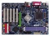
GA-8I848P775-G Motherboard Layout KB_MS USB LGA775 ATX_12V CPU_FAN ATX COMA LPT GA-8I848P775-G DDR1 DDR2 DDR3 COMB LAN USB CLR_CMOS F_AUDIO AUDIO CD_IN Marvell 8001 CODEC SUR_CEN IT8712 CI SPDIF_IO Intel 848P AGP FDD BAT PCI1 ICH5 PCI2 PCI3 BIOS SATA0 SATA1 PCI4 IDE2 IDE1 - Gigabyte GA-8I848P775-G | Manual - Page 7
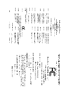
266/333/400MHz ZCLK (66MHz) HCLK+/- (133/200MHz) 66MHz 33 MHz 48 MHz 14.318 MHz BIOS ICH5 LPC BUS IT8712 24 MHz Floppy LPT Port PCICLK (33MHz) MIC LINE-IN LINE-OUT AC97 CODEC 8 USB Ports ATA33/66/100 33 MHz IDE Channels Serial ATA Channels PS/2 KB/Mouse COM Ports - 7 - - Gigabyte GA-8I848P775-G | Manual - Page 8
- 8 - - Gigabyte GA-8I848P775-G | Manual - Page 9
instructions below: 1. Please turn off the computer and unplug its power cord. 2. When handling the motherboard , avoid touching any metal leads or connectors. 3. It is best to wear an electrostatic discharge (ESD) cuff when handling electronic components (CPU motherboard problem manual - Gigabyte GA-8I848P775-G | Manual - Page 10
Onboard LAN Onboard Audio I/O Control Š Supports the latest Intel® Pentium® 4 LGA775 CPU Š Supports 800/533MHz FSB Š L2 cache varies with CPU Š Northbridge: Intel® 848P Chipset Š Southbridge: Intel® ICH5 Š 3 DDR DIMM memory slots (supports up to 2GB memory) Š Supports 2.5V DDR DIMM Š Supports DDR - Gigabyte GA-8I848P775-G | Manual - Page 11
speed detection Š CPU warning temperature Š CPU / System fan failure warning Š CPU smart fan control Š Use of licensed AWARD BIOS Š Supports Q-Flash Š Supports @BIOS Š Supports EasyTune (only supports Hardware Monitor function) Š Over Voltage via BIOS (CPU/DDR/AGP) Š Over Clock via BIOS (CPU/DDR/AGP - Gigabyte GA-8I848P775-G | Manual - Page 12
specifications, please do so according to your hardware specifications including the CPU, graphics card, memory, hard drive, etc. HT functionality requirement content : Enabling the functionality of Hyper-Threading CPU during installation.) GA-8I848P775-G Motherboard - 12 - Fig. 4 Once the CPU - Gigabyte GA-8I848P775-G | Manual - Page 13
the CPU and make sure the push pins aim to the pin hole on the motherboard.Pressing down the push pins diagonally. Fig. 4 Please make sure the Male and Female push pin are joined closely. (for detailed installation instructions, please refer to the heatsink installation section of the user manual - Gigabyte GA-8I848P775-G | Manual - Page 14
and specifications. Memory modules are designed so that they can be inserted only in one direction. The memory capacity used can differ with each slot. Notch DDR DDR1 S D D D S S DDR2 S S D X D X DDR3 S S X D X D D:Double Sided DIMM S:Single Sided DIMM X:Not Use GA-8I848P775-G Motherboard - Gigabyte GA-8I848P775-G | Manual - Page 15
English 1. The DIMM slot has a notch, so the DIMM memory module can only fit in one direction. 2. Insert the DIMM memory module vertically into the DIMM slot. Then push it down. 3. Close the plastic clip at both edges of the DIMM slots to lock the DIMM - Gigabyte GA-8I848P775-G | Manual - Page 16
outlined below: 1. Read the related expansion card's instruction document before install the expansion card into the computer the computer, if necessary, setup BIOS utility of expansion card from BIOS. 8. Install related driver from the operating system. Installing a GA-8I848P775-G Motherboard - 16 - - Gigabyte GA-8I848P775-G | Manual - Page 17
USB keyboard, mouse, scanner, zip, speaker...etc. have a standard USB interface. Also make sure your OS supports USB controller. If your OS does not support USB controller, please contact OS vendor for possible patch or driver upgrade . LAN Port The provided Internet connection is Gigabit Ethernet, - Gigabyte GA-8I848P775-G | Manual - Page 18
5) FDD 6) IDE1/IDE2 7) SATA0 / SATA1 8) F_PANEL 9) F_AUDIO 10) CD_IN 11) SPDIF_IO 12) SUR_CEN 13) F_USB1 / F_USB2 14) CI 15) CLR_CMOS 16) PWR_LED (Optional) 17) BAT GA-8I848P775-G Motherboard - 18 - - Gigabyte GA-8I848P775-G | Manual - Page 19
all components and devices are properly installed. Align the power connector with its proper location on the motherboard and connect tightly. The ATX_12V power connector mainly supplies power to the CPU. If the ATX_12V power connector is not connected, the system will not start. Caution! Please use - Gigabyte GA-8I848P775-G | Manual - Page 20
the CPU fan to prevent CPU overheating and failure. 1 CPU_FAN 1 SYS_FAN Pin No. 1 2 3 4 Definition GND +12V Sense Speed Control ( drives supported are: 360KB, 720KB, 1.2MB, 1.44MB and 2.88MB. Please connect the red power connector wire to the pin1 position. 34 33 GA-8I848P775-G Motherboard 2 - Gigabyte GA-8I848P775-G | Manual - Page 21
the other as Slave (for information on settings, please refer to the instructions located on the IDE device). 39 1 40 2 7) SATA0/SATA1 up to 150MB/s transfer rate. Please refer to the BIOS setting for the Serial ATA and install the proper driver in order to work properly. Pin No. Definition 1 - Gigabyte GA-8I848P775-G | Manual - Page 22
1: Power Pin 2- Pin 3: NC Pin 4: Data(-) Open: Normal Close: Reset Hardware System Open: Normal Close: Power On/Off Pin 1: LED anode(+) Pin 2: LED cathode(-) NC GA-8I848P775-G Motherboard - 22 - - Gigabyte GA-8I848P775-G | Manual - Page 23
the MB header. To find out if the chassis you are buying support front audio connector, please contact your dealer.Please note, you can have the alternative of using front audio connector or of using rear audio connector to play sound. 1 2 9 10 Pin No. 1 2 3 4 5 6 7 8 9 10 Definition MIC GND - Gigabyte GA-8I848P775-G | Manual - Page 24
SPDIF_IO (SPDIF In/Out) The SPDIF output is capable of providing digital audio to external speakers or compressed AC3 data to an external Dolby Digital Decoder. 7 8 Pin No. 1 2 3 4 5 6 7 8 Definition SUR OUTL SUR OUTR GND No Pin CENTER_OUT BASS_OUT AUX_L AUX_R GA-8I848P775-G Motherboard - 24 - - Gigabyte GA-8I848P775-G | Manual - Page 25
1 Power 2 10 2 Power 3 USB DX- 4 USB Dy- 1 9 5 USB DX+ 6 USB Dy+ 7 GND 8 GND 9 No Pin 10 NC 14) CI (Chassis Intrusion, Case Open) This 2-pin connector allows your system to detect if the chassis cover is removed. You can check the "Case Opened" status in BIOS Setup. Pin No - Gigabyte GA-8I848P775-G | Manual - Page 26
power indicator to indicate whether the system is on/off. It will blink when the system enters suspend mode. Pin No. Definition 1 MPD+ 1 2 MPD- 3 MPD- GA-8I848P775-G Motherboard - 26 - - Gigabyte GA-8I848P775-G | Manual - Page 27
is incorrectly replaced. Replace only with the same or equivalent type recommended by the manufacturer. Dispose of used batteries according to the manufacturer's instructions. If you want to erase CMOS... 1.Turn OFF the computer and unplug the power cord. 2.Remove the battery, wait for 30 second - Gigabyte GA-8I848P775-G | Manual - Page 28
English GA-8I848P775-G Motherboard - 28 - - Gigabyte GA-8I848P775-G | Manual - Page 29
quickly and easily update or backup BIOS without entering the operating system. @BIOS is a Windows-based utility that does not require users to boot to DOS before upgrading BIOS but directly download and update BIOS from the Internet. CONTROL KEYS Enter> - Gigabyte GA-8I848P775-G | Manual - Page 30
F1" to search the advanced option hidden. „ Standard CMOS Features This setup page includes all the items in standard compatible BIOS. „ Advanced BIOS voltage, fan, speed. „ Frequency/Voltage Control This setup page is control CPU clock and frequency ratio. „ Load GA-8I848P775-G Motherboard - 30 - - Gigabyte GA-8I848P775-G | Manual - Page 31
Extended Memory Total Memory KLJI: Move Enter: Select F5: Previous Values 640K 127M 128M +/-/PU/PD: Value F6: Fail-Safe Defaults F10: Save 1999 to 2098 ESC: Exit F1: General Help F7: Optimized Defaults Date The date format is , , , . Week The week, from - Gigabyte GA-8I848P775-G | Manual - Page 32
You can use one of three methods: Auto Allows BIOS to automatically detect IDE devices during POST(default) None step and allow for faster system start up. Manual User can manually input the correct settings Access Mode Use this to drive; 2.88M byte capacity. GA-8I848P775-G Motherboard - 32 - - Gigabyte GA-8I848P775-G | Manual - Page 33
English Floppy 3 Mode Support (for Japan Area) memory installed on the motherboard. Extended Memory The BIOS determines how much extended memory is present during the POST. This is the amount of memory located above 1 MB in the CPU's memory address map. Total Memory This item displays the memory - Gigabyte GA-8I848P775-G | Manual - Page 34
-Copyright (C) 1984-2005 Award Software Advanced BIOS Features X Hard Disk Boot Priority First Boot Device Second Boot Device Third Boot Device Password Check # CPU Hyper-Threading Limit CPUID Max. to 3 [Press , please just press ENTER to make [SETUP] empty. GA-8I848P775-G Motherboard - 34 - - Gigabyte GA-8I848P775-G | Manual - Page 35
for operating system with multi processors mode supported. (Default value) Disabled Disables CPU Hyper Threading. Limit CPUID Max. to 3 Enabled Limit CPUID Maximum value to 3 when use older OS like NT4. Disabled Disables CPUID Limit for windows XP. (Default value) 2-3 Integrated Peripherals - Gigabyte GA-8I848P775-G | Manual - Page 36
USB 2.0 Controller. (Default value) Disable USB 2.0 Controller. USB Keyboard Support Enabled Enable USB Keyboard Support. Disabled Disable USB Keyboard Support. (Default value) USB Mouse Support Enabled Disabled Enable USB Mouse Support. Disable USB Mouse Support. (Default value) AC97 Audio - Gigabyte GA-8I848P775-G | Manual - Page 37
English Onboard Serial Port 2 Auto BIOS will automatically setup the port 2 address. 3F8/IRQ4 Enable onboard Serial port 2 and address is 3F8/IRQ4. 2F8/IRQ3 Enable onboard mode. ECP Mode Use DMA 3 Set ECP Mode Use DMA to 3. (Default value) 1 Set ECP Mode Use DMA to 1. - 37 - BIOS Setup - Gigabyte GA-8I848P775-G | Manual - Page 38
Enter: Select F5: Previous Values +/-/PU/PD: Value F10: Save F6: Fail-Safe Defaults ESC: Exit F1: General Help F7: Optimized Defaults ACPI Suspend Type S1(POS) S3(STR) Set ACPI suspend type to function. Enabled Enable PME Event Wake up. (Default value) GA-8I848P775-G Motherboard - 38 - - Gigabyte GA-8I848P775-G | Manual - Page 39
on the LAN can awake the system from any suspend state. Disabled Disable Modem Ring on/wake on Lan function. Enabled Enable Modem Ring on/wake on Lan. (Default to the system, the system always in "On" state. Memory When AC-power back to the system, the system will return to the Last state before - Gigabyte GA-8I848P775-G | Manual - Page 40
Move Enter: Select F5: Previous Values +/-/PU/PD: Value F10: Save F6: Fail-Safe Defaults ESC: Exit F1: General Help F7: Optimized Defaults PCI 1/PCI 5 IRQ Assignment Auto Auto assign IRQ to PCI 1/PCI 5. 12,14,15 Set IRQ 3,4,5,7,9,10,11,12,14,15 to PCI 4. GA-8I848P775-G Motherboard - 40 - - Gigabyte GA-8I848P775-G | Manual - Page 41
CPU Temperature Current CPU FAN Speed Current SYSTEM FAN Speed CPU Warning Temperature CPU FAN Fail Warning SYSTEM FAN Fail Warning CPU Smart FAN Control CPU : Save ESC: Exit F6: Fail-Safe Defaults F7: Optimized Defaults F1: General Help Reset Case Open Status Disabled Enabled Don't reset case - Gigabyte GA-8I848P775-G | Manual - Page 42
option can be used for CPU fans with 3-pin or 4-pin power cables. However, some 4-pin CPU fan power cables are not designed following Intel 4-Wire fans PWM control specifications. With such CPU fans, selecting PWM will not effectively reduce the fan speed. GA-8I848P775-G Motherboard - 42 - - Gigabyte GA-8I848P775-G | Manual - Page 43
Award Software Frequency/Voltage Control CPU Clock Ratio CPU Host Clock Control x CPU Host Frequency (Mhz) x AGP/PCI/SRC Fixed Memory Frequency For Memory Frequency (Mhz) AGP/PCI/SRC Frequency (Mhz) DIMM OverVoltage Control AGP OverVoltage Control CPU OverVoltage Control [15X] [Disabled] 200 66 - Gigabyte GA-8I848P775-G | Manual - Page 44
Control Normal Set CPU Voltage Control to Normal. (Default value) +5.0% +7.5% Set CPU Voltage Control to +5.0%. Set CPU Voltage Control to +7.5%. +10.0% Set CPU Voltage Control to +10.0%. Incorrect using it may cause your system broken. For power End-User use only! GA-8I848P775-G Motherboard - Gigabyte GA-8I848P775-G | Manual - Page 45
Setup Utility-Copyright (C) 1984-2005 Award Software ` Standard CMOS Features ` Advanced BIOS Features ` Integrated Peripherals ` Power Management Setup ` PnP/PCI Configurations ` PC Health Status ` Frequency/Voltage Control ESC: Quit F8: Q-Flash Load Fail-Safe Defaults Load Optimized Defaults Set - Gigabyte GA-8I848P775-G | Manual - Page 46
in Advance BIOS Features Menu, you will be prompted for the password every time the system is rebooted or any time you try to enter Setup Menu. If you select "Setup" at "Password Check" in Advance BIOS Features Menu, you will be prompted only when you try to enter Setup. GA-8I848P775-G Motherboard - Gigabyte GA-8I848P775-G | Manual - Page 47
Setup Utility-Copyright (C) 1984-2005 Award Software ` Standard CMOS Features ` Advanced BIOS Features ` Integrated Peripherals ` Power Management Setup ` PnP/PCI Configurations ` PC Health Status ` Frequency/Voltage Control ESC: Quit F8: Q-Flash Load Fail-Safe Defaults Load Optimized Defaults Set - Gigabyte GA-8I848P775-G | Manual - Page 48
English GA-8I848P775-G Motherboard - 48 - - Gigabyte GA-8I848P775-G | Manual - Page 49
will continue to install other drivers. System will reboot automatically after install the drivers, afterward you can install others application. For USB2.0 driver support under Windows XP operating system, please use Windows Service Pack. After install Windows Service Pack, it will show a question - Gigabyte GA-8I848P775-G | Manual - Page 50
English 3-2 Software Application This page displays all the tools that Gigabyte developed and some free software. You can click an item to install it. 3-3 Software Information This page lists the contents of software and drivers in this CD-title. GA-8I848P775-G Motherboard - 50 - - Gigabyte GA-8I848P775-G | Manual - Page 51
English 3-4 Hardware Information This page lists all device you have for this motherboard. 3-5 Contact Us Please see the last page for details. - 51 - Drivers Installation - Gigabyte GA-8I848P775-G | Manual - Page 52
English GA-8I848P775-G Motherboard - 52 - - Gigabyte GA-8I848P775-G | Manual - Page 53
-supported VGA cards How to use the Xpress Recovery2 Initial access by booting from CD-ROM and subsequent access by pressing the F9 key: Steps: After entering BIOS Setup, go to Advanced BIOS Feature and set to boot from CD-ROM. Save the settings and exit the BIOS Setup. Insert the provided driver - Gigabyte GA-8I848P775-G | Manual - Page 54
supports only PATA hard disks and not SATA hard disks on the following motherboards (As this is a BIOS-related issue, it can be solved by BIOS update) GA-K8U GA-K8U-9 GA-K8NXP-SLI GA-K8N Ultra-SLI GA-K8N Pro-SLI GA-8I848P775-G Motherboard GA-K8NXP-9 GA-K8N Ultra-9 GA-K8NF-9 (PCB Ver. 1.0) GA - Gigabyte GA-8I848P775-G | Manual - Page 55
BIOS menu. The BIOS upgrading guides below are separated into two parts. If your motherboard has dual-BIOS, please refer to Part One. If your motherboard has single-BIOS, please refer to Part Two. Part One: Updating BIOS with Q-FlashTM Utility on Dual BIOS Motherboards. Some of Gigabyte motherboards - Gigabyte GA-8I848P775-G | Manual - Page 56
Enter key on your keyboard to enable execution of the task. Action bar: Contains the names of four actions needed to operate the Q-Flash/Dual BIOS utility. Pressing the buttons mentioned on your keyboards to perform these actions. GA-8I848P775-G Motherboard - 56 - - Gigabyte GA-8I848P775-G | Manual - Page 57
flash and press Enter. In this example, we only download one BIOS file to the floppy disk so only one BIOS file, 8KNXPU.Fba, is listed. Please confirm again you have the correct BIOS file for your motherboard. Dual BIOS Utility Boot From Main Bios Main ROM Type/Size SST 49LF003A Backup ROM Type - Gigabyte GA-8I848P775-G | Manual - Page 58
OK Memory Frequency 266 MHz in Single Channel Primary Master : FUJITSU MPE3170AT ED-03-08 Primary Slave : None Secondary Master : CREATIVEDVD-RM DVD1242E BC101 Secondary Slave : None Press DEL to enter SETUP / Dual BIOS / Q-Flash / F9 For Xpress Recovery 09/23/2003-i875P-6A79BG03C-00 GA-8I848P775 - Gigabyte GA-8I848P775-G | Manual - Page 59
Disk Type... Press Y on your keyboard to save and exit. Part Two: Updating BIOS with Q-FlashTM Utility on Single-BIOS Motherboards. This part guides users of single-BIOS motherboards how to update BIOS using the Q-FlashTM utility. CMOS Setup Utility-Copyright (C) 1984-2004 Award Software Standard - Gigabyte GA-8I848P775-G | Manual - Page 60
SyCs:tRemeset F10:Power Off Do not turn off power or reset your system at this stage!! After BIOS file is read, you'll see a confirmation dialog box asking you "Are you sure to update BIOS?" Please do not take out the floppy disk when it begins flashing BIOS. GA-8I848P775-G Motherboard - 60 - - Gigabyte GA-8I848P775-G | Manual - Page 61
file becomes F4 after updating Award Modular BIOS v6.00PG, An Energy Star Ally Copyright (C) 1984-2003, Award Software, Inc. Intel 845GE AGPSet BIOS for 8GE800 F4 Check System Health OK Main Processor : Intel Pentium(R) 4 1.7GHz (100x17.0) Memory Testing : 122880K OK - Gigabyte GA-8I848P775-G | Manual - Page 62
b. Click "Update New BIOS" c. Please select "All Files" in dialog box while opening the old file. d. Please search for BIOS unzip file, downloading from internet or any other methods (such as: 8I848P775-G.E7). e. Complete update process following the instruction. GA-8I848P775-G Motherboard - 62 - - Gigabyte GA-8I848P775-G | Manual - Page 63
II, be sure that motherboard's model name in BIOS unzip file are the same as your motherboard's. Otherwise, your system won't boot. III. In method I, if the BIOS file you need cannot be found in @BIOSTM server, please go onto Gigabyte's web site for downloading and updating it according to method - Gigabyte GA-8I848P775-G | Manual - Page 64
driver, you find a icon a Sound Effect icon on the lower right hand taskbar. Click the icon to select the function. Line Out STEP 3: Click "Speaker Configuration" then click on the left selection bar and select "2CH Speaker" to complete 2 channel audio configuration. GA-8I848P775-G Motherboard - Gigabyte GA-8I848P775-G | Manual - Page 65
Output Mode STEP 1 : Connect the front channels to "Line Out", the rear channels to "Line In". STEP 2 : Following installation of the audio driver, you find a icon a Sound Effect icon on the lower right hand taskbar. Click the icon to select the function. Line Out Line In STEP 3 : Click " - Gigabyte GA-8I848P775-G | Manual - Page 66
Center/Subwoofer channels to "MIC In". MIC In Line Out STEP 2 : Following installation of the audio driver, you find a icon a Sound Effect icon on the lower right hand taskbar. Click the icon bar and select "6CH Speaker" to complete 6 channel audio configuration. GA-8I848P775-G Motherboard - 66 - - Gigabyte GA-8I848P775-G | Manual - Page 67
. STEP 2 : Connect the Surround-Kit to the SUR_CEN connector located on the motherboard. STEP 3 : There are two methods of 8 channel audio configuration: Method 1: Connect the front channels to the "LINE OUT" port located on the audio panel and the rear channels to the Surround-Kit "REAR R/L" port - Gigabyte GA-8I848P775-G | Manual - Page 68
(This method requires UAJ function) STEP 4 : Following installation of the audio driver, you find a icon a Sound Effect icon on the lower right audio configuration. Sound Effect Configuration: At the sound effect menu, users can adjust sound option settings as desired. GA-8I848P775-G Motherboard - Gigabyte GA-8I848P775-G | Manual - Page 69
SPDIF Output Device (Optional Device) A "SPDIF output" connector is available on the motherboard. Cable with rear bracket is provided and could link to the "SPDIF output" connector (As picture.) For the further linkage to decoder, rear bracket provides - Gigabyte GA-8I848P775-G | Manual - Page 70
Line Out jack, and microphone to MIC In jack. Auto-detecting: Please connect the devices to the right jacks as above. A window will appear as right picture if you setup the devices properly. Please note that 3D audio function will only appear when 3D audio inputs. GA-8I848P775-G Motherboard - 70 - - Gigabyte GA-8I848P775-G | Manual - Page 71
: If the device picture shows different from what you set, please press "Manual Selection" to set. UAJ Introduction UAJ (Universal Audio Jack) has a very smart feature: It will switch signal automatically when user plugs his audio device to the wrong jack (Line-in/ Line-out). That means users - Gigabyte GA-8I848P775-G | Manual - Page 72
English 4-2 Troubleshooting Below is a collection of general asked questions. To check general asked questions based on a specific motherboard model, please log on to http://www.gigabyte.com.tw Question 1: I cannot see some options that were included in previous BIOS after updating BIOS. Why? - Gigabyte GA-8I848P775-G | Manual - Page 73
- 73 - Appendix English - Gigabyte GA-8I848P775-G | Manual - Page 74
English GA-8I848P775-G Motherboard - 74 - - Gigabyte GA-8I848P775-G | Manual - Page 75
- 75 - Appendix English - Gigabyte GA-8I848P775-G | Manual - Page 76
English GA-8I848P775-G Motherboard - 76 - - Gigabyte GA-8I848P775-G | Manual - Page 77
- 77 - Appendix English - Gigabyte GA-8I848P775-G | Manual - Page 78
English GA-8I848P775-G Motherboard - 78 - - Gigabyte GA-8I848P775-G | Manual - Page 79
.giga-byte.com U.S.A. G.B.T. INC. TEL: +1-626-854-9338 FAX: +1-626-854-9339 Tech. Support : http://tw.giga-byte.com/TechSupport/ServiceCenter.htm Non-Tech. Support(Sales/Marketing) : http://ggts.gigabyte.com.tw/nontech.asp WEB address : http://www.giga-byte.com Germany G.B.T. TECHNOLOGY TRADING GMBH - Gigabyte GA-8I848P775-G | Manual - Page 80
cz Romania Representative Office Of GIGA-BYTE Technology Co., Ltd. in Romania Tech. Support : http://tw.giga-byte.com/TechSupport/ServiceCenter.htm Non-Tech. Support(Sales/Marketing) : http://ggts.gigabyte.com.tw/nontech.asp WEB address: http://www.gigabyte.com.ro GA-8I848P775-G Motherboard - 80 -
-
 1
1 -
 2
2 -
 3
3 -
 4
4 -
 5
5 -
 6
6 -
 7
7 -
8
-
9
-
10
-
11
-
12
-
13
-
14
-
15
-
16
-
17
-
18
-
19
-
20
-
21
-
22
-
23
-
24
-
25
-
26
-
27
-
28
-
29
-
30
-
31
-
32
-
33
-
34
-
35
-
36
-
37
-
38
-
39
-
40
-
41
-
42
-
43
-
44
-
45
-
46
-
47
-
48
-
49
-
50
-
51
-
52
-
53
-
54
-
55
-
56
-
57
-
58
-
59
-
60
-
61
-
62
-
63
-
64
-
65
-
66
-
67
-
68
-
69
-
70
-
71
-
72
-
73
-
74
-
75
-
76
-
77
-
78
-
79
-
80
 |
 |

GA-8I848P775-G
Intel
®
Pentium
®
4 LGA775 Processor Motherboard
User's Manual
Rev. 1003
12ME-8I848PTG-1003
*
The WEEE marking on the product indicates this product must not be disposed of with user's other household waste
and must be handed over to a designated collection point for the recycling of waste electrical and electronic equipment!!
*
The WEEE marking applies only in European Union's member states.