Gigabyte GA-8I865G775-G Manual
Gigabyte GA-8I865G775-G Manual
 |
View all Gigabyte GA-8I865G775-G manuals
Add to My Manuals
Save this manual to your list of manuals |
Gigabyte GA-8I865G775-G manual content summary:
- Gigabyte GA-8I865G775-G | Manual - Page 1
GA-8I865G775-G / GA-8I865G775-G-RH Intel® Pentium® 4 LGA775 Processor Motherboard User's Manual Rev. 2002 12ME-8I865GTG-2002R * The WEEE marking on the product indicates this product must not be disposed of with user's other household waste and must - Gigabyte GA-8I865G775-G | Manual - Page 2
Motherboard GA-8I865G775-G Apr. 18, 2006 Motherboard GA-8I865G775-G Apr. 18, 2006 - Gigabyte GA-8I865G775-G | Manual - Page 3
Motherboard GA-8I865G775-G-RH Jun. 2, 2006 Motherboard GA-8I865G775-G-RH Jun. 2, 2006 - Gigabyte GA-8I865G775-G | Manual - Page 4
product information and specifications, please carefully read the "User's Manual." „ For detailed information related to Gigabyte's unique features, please go to the "Technology Guide" section on Gigabyte's website to read or download the information you need. For more product details, please visit - Gigabyte GA-8I865G775-G | Manual - Page 5
Table of Contents ItemChecklist ...7 OptionalAccessories ...7 GA-8I865G775-G(-RH) Motherboard Layout 8 Block Diagram ...9 Chapter 1 Hardware Installation 11 1-1 Considerations Prior to Installation 11 1-2 Feature Summary 12 1-3 Installation of the CPU and Heatsink 14 1-3-1 Installation of the - Gigabyte GA-8I865G775-G | Manual - Page 6
Information 55 3-5 Contact Us ...55 Chapter 4 Appendix 57 4-1 Unique Software Utilities 57 4-1-1 EasyTune 5 Introduction 57 4-1-2 Xpress Recovery2 Introduction 58 4-1-3 Flash BIOS Method Introduction 60 4-1-4 2 / 4 / 6 Channel Audio Function Introduction 69 4-2 Troubleshooting 75 - 6 - - Gigabyte GA-8I865G775-G | Manual - Page 7
Item Checklist IDE Cable x 1 FDD Cable x 1 Serial ATA Cable x 1 I/O Shield * The items listed above are for reference only, and are subject to change without notice. Optional Accessories Š 2 Ports USB2.0 Cable (Part Number: 12CR1-1UB030-51/-51R) Š COM Port Cable (Part Number: 12CF1-1CM001-31/-31R) - - Gigabyte GA-8I865G775-G | Manual - Page 8
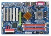
GA-8I865G775-G(-RH) Motherboard Layout KB_MS LGA775 ATX_12V CPU_FAN COMA LPT GA-8I865G775 -G(-RH) DDR1 VGA ATX R_USB USB_LAN AUDIO F_AUDIO Intel 865G DDR4 DDR3 DDR2 AGP Marvell 8001 CODEC CD_IN SUR_CEN IT8712 AUX_IN CI COMB SPDIF_O PCI1 ICH5 PCI2 IDE1 IDE2 BAT CLR_CMOS FDD - Gigabyte GA-8I865G775-G | Manual - Page 9
Block Diagram AGP 8X/4X VGA LGA775 Processor Host Interface Intel 865G GMCH DDR 400/333/266MHz DIMM Dual Channel Memory PCI Bus Intel ICH5 Marvell 8001 RJ45 5 PCI PCICLK (33MHz) MIC Line-Out Line-In CODEC 8 USB Ports BIOS 2 Serial ATA ATA33/66/100 IDE Channels IT8712 Floppy LPT Port COM - Gigabyte GA-8I865G775-G | Manual - Page 10
- 10 - - Gigabyte GA-8I865G775-G | Manual - Page 11
instructions below: 1. Please turn off the computer and unplug its power cord. 2. When handling the motherboard , avoid touching any metal leads or connectors. 3. It is best to wear an electrostatic discharge (ESD) cuff when handling electronic components (CPU motherboard problem manual - Gigabyte GA-8I865G775-G | Manual - Page 12
CPU Š Supports LGA775 Intel® Processor Pentium® 4(Note 1) Š L2 cache varies with CPU Front Side Bus Š Supports 800/533MHz FSB Chipset Š Northbridge:Intel® 865G Š Southbridge: Intel® ICH5 LAN Š 2 USB 2.0/1.1 connectors for additional 4 ports by cables GA-8I865G775-G(-RH) Motherboard - 12 - - Gigabyte GA-8I865G775-G | Manual - Page 13
speed detection Š CPU warning temperature Š CPU System fan failure warning Š CPU smart fan control BIOS Š 1 4Mbit flash ROM Š Use of licensed AWARD BIOS Additional Features Š Supports @BIOS Š Supports Download Center Š Supports Q-Flash Š Supports EasyTune (only supports Hardware Monitor - Gigabyte GA-8I865G775-G | Manual - Page 14
: Enabling the functionality of Hyper-Threading Technology for your computer system requires all of the following platform components: - CPU: An Intel® Pentium 4 Processor with HT Technology - Chipset: An Intel® Chipset that supports HT Technology - BIOS: A BIOS that supports HT Technology and has - Gigabyte GA-8I865G775-G | Manual - Page 15
instruction is only for Intel boxed fan) Fig. 3 Place the heatsink atop the CPU and make sure the push pins aim to the pin hole on the motherboard. installation instructions, please refer to the heatsink installation section of the user manual) Fig. 5 Please check the back of motherboard after - Gigabyte GA-8I865G775-G | Manual - Page 16
are unable to insert the module, please switch the direction. The motherboard supports DDR memory modules, whereby BIOS will automatically detect memory capacity and specifications. Memory modules are designed the DIMM module. DDR memory module Fig. 1 Fig. 2 GA-8I865G775-G(-RH) Motherboard - 16 - - Gigabyte GA-8I865G775-G | Manual - Page 17
instruction into expansion slot in motherboard. 4. Be sure BIOS. 8. Install related driver from the operating system. Installing a AGP expansion card: Please carefully pull out the small whitedrawable bar at the end of the AGP slot when you try to install/uninstall the VGA card. Please align the VGA - Gigabyte GA-8I865G775-G | Manual - Page 18
. VGA Port Monitor can be connected to VGA port supports USB controller. If your OS does not supportUSB controller, please contact OS vendor for possible patch or driver upgrade. For more information please contact your OS or device(s) vendors. LAN Port The LAN GA-8I865G775-G(-RH) Motherboard - 18 - - Gigabyte GA-8I865G775-G | Manual - Page 19
English 1-7 Connectors Introduction 1 3 2 10 19 18 5 11 13 6 7 12 8 14 16 17 4 15 9 1) ATX_12V 2) ATX (Power Connector) 3) CPU_FAN 4) SYS_FAN 5) IDE1 / IDE2 6) FDD 7) SATA0 / SATA1 8) F_PANEL 9) PWR_LED 10) F_AUDIO 11) CD_IN 12) AUX_IN 13) SUR_CEN 14) SPDIF_O 15) F_USB1 / F_USB2 16) - Gigabyte GA-8I865G775-G | Manual - Page 20
Align the power connector with its proper location on the motherboard and connect tightly. The ATX_12V power connector mainly supplies power to the CPU. If the ATX_12V power connector is not connected, the 15 GND 16 GND 17 GND 18 -5V 19 +5V 20 +5V GA-8I865G775-G(-RH) Motherboard - 20 - - Gigabyte GA-8I865G775-G | Manual - Page 21
wire (GND). Remember to connect the CPU/system fan cable to the CPU_FAN/SYS_FAN connector to prevent CPU damage or system hanging caused by overheating. other as Slave (for information on settings, please refer to the instructions located on the IDE device). Before attaching the IDE cable, please - Gigabyte GA-8I865G775-G | Manual - Page 22
to the FDD drive. The types of FDD drives supported are: 360KB, 720KB, 1.2MB, 1.44MB and 2.88MB BIOS setting for the Serial ATA and install the proper driver in order to work properly. Pin No. Definition 1 GND 7 1 2 TXP 3 TXN 4 GND 5 RXN 6 RXP 7 GND GA-8I865G775-G(-RH) Motherboard - Gigabyte GA-8I865G775-G | Manual - Page 23
English 8) F_PANEL (Front Panel Connector) Please connect the power LED, PC speaker, reset switch and power switch etc. of your chassis front panel to the F_PANEL connector according to the pin assignments below. Message LED/ Power/ Sleep LED Speaker Connector Power Switch MSG+ MSG- PW+ PWSPEAK+ - Gigabyte GA-8I865G775-G | Manual - Page 24
assigments on the MB header. To find out if the chassis you are buying support front audio connector, please contact your dealer.Please note, you can have the (R) 6 Rear Audio (R)/ Return R 7 NC 8 No Pin 9 FrontAudio (L) 10 Rear Audio (L)/ Return L GA-8I865G775-G(-RH) Motherboard - 24 - - Gigabyte GA-8I865G775-G | Manual - Page 25
English 11) CD_IN (CD IN Connector) Connect CD-ROM or DVD-ROM audio out to the connector. Pin No. Definition 1 1 CD-L 2 GND 3 GND 4 CD-R 12) AUX_IN (AUX In Connector) Connect other device (such as PCI TV Tunner audio out) to the connector. Pin No. Definition 1 1 AUX-L 2 GND 3 GND - Gigabyte GA-8I865G775-G | Manual - Page 26
make the device unable to work or even damage it. For optional SPDIFO cable, please contact your local dealer. Pin No. Definition 1 Power 1 2 SPDIFO 3 GND GA-8I865G775-G(-RH) Motherboard - 26 - - Gigabyte GA-8I865G775-G | Manual - Page 27
English 15) F_USB1 / F_USB2 (Front USB Connectors) Be careful with the polarity of the front USB connector. Check the pin assignment carefully while you connect the front USB cable, incorrect connection between the cable and connector will make the device unable to work or even damage it. For - Gigabyte GA-8I865G775-G | Manual - Page 28
allows your system to detect if the chassis cover is removed. You can check the "Case Opened" status in BIOS Setup. Pin No. Definition 1 1 Signal 2 GND 18) CLR_CMOS (Clear CMOS) You may clear the use of this header. Open: Normal Short: Clear CMOS GA-8I865G775-G(-RH) Motherboard - 28 - - Gigabyte GA-8I865G775-G | Manual - Page 29
is incorrectly replaced. Replace only with the same or equivalent type recommended by the manufacturer. Dispose of used batteries according to the manufacturer's instructions. If you want to erase CMOS... 1. Turn OFF the computer and unplug the power cord. 2. Take out the battery gently and put it - Gigabyte GA-8I865G775-G | Manual - Page 30
English GA-8I865G775-G(-RH) Motherboard - 30 - - Gigabyte GA-8I865G775-G | Manual - Page 31
BIOS, either GIGABYTE's Q-Flash or @BIOS utility can be used. Q-Flash allows the user to quickly and easily update or backup BIOS without entering the operating system. @BIOS is a Windows-based utility that does not require users to boot to DOS before upgrading BIOS but directly download and update - Gigabyte GA-8I865G775-G | Manual - Page 32
in the BIOS when somehow the system works not stable as usual. This action makes the system reset to the default for stability. The BIOS Setup menus described in this chapter are for reference only and may differ from the exact settings for your motherboard. GA-8I865G775-G(-RH) Motherboard - 32 - Gigabyte GA-8I865G775-G | Manual - Page 33
setup page includes all the items in standard compatible BIOS. „ Advanced BIOS Features This setup page includes all the items of voltage, fan, speed. „ MB Intelligent Tweaker(M.I.T.) This setup page is control CPU clock and frequency ratio. „ Load Fail-Safe Defaults Fail-Safe Defaults indicates - Gigabyte GA-8I865G775-G | Manual - Page 34
` IDE Channel 3 Master Drive A Drive B Floppy 3 Mode Support Halt On [None] [None] [None] [None] [None] , from Sun to Sat, determined by the BIOS and is display only Month The month, Jan system start up. • Manual User can manually input the correct settings GA-8I865G775-G(-RH) Motherboard - 34 - - Gigabyte GA-8I865G775-G | Manual - Page 35
inch double-sided drive; 2.88M byte capacity. Floppy 3 Mode Support (for Japan Area) Disabled Normal Floppy Drive. (Default value) motherboard. Extended Memory The BIOS determines how much extended memory is present during the POST. This is the amount of memory located above 1 MB in the CPU - Gigabyte GA-8I865G775-G | Manual - Page 36
be denied if the correct password is not entered at the prompt. (Default value) (Note) This item will show up when you install a processor which supports this function. GA-8I865G775-G(-RH) Motherboard - 36 - - Gigabyte GA-8I865G775-G | Manual - Page 37
supported. (Default value) Disables CPU Hyper Threading. Limit CPUID Max. to 3 Enabled Limit CPUID Maximum value to 3 when use older OS like NT4. Disabled Disables CPUID Limit for windows Note) This item will show up when you install a processor which supports this function. - 37 - BIOS Setup - Gigabyte GA-8I865G775-G | Manual - Page 38
. (Default value) Manual Set SATA mode manually from "SATA Port0 configure supported by Windows XP or later. (Default value) SATA Port1 Set SATA controller to native mode(Serial ATA mode - SATA Port 1). This mode is only supported by Windows XP or later. GA-8I865G775-G(-RH) Motherboard - Gigabyte GA-8I865G775-G | Manual - Page 39
Boot ROM This function decide whether to invoke the boot ROM of the onboard LAN chip. Enabled Disabled Enable this function. Disable this function. (Default value) Onboard Serial Port 1 Auto BIOS will automatically setup the Serial port 1 address. 3F8/IRQ4 2F8/IRQ3 Enable onboard Serial port - Gigabyte GA-8I865G775-G | Manual - Page 40
Parallel port as ECP and EPP mode. ECP Mode Use DMA 3 Set ECP Mode Use DMA to 3. (Default value) 1 Set ECP Mode Use DMA to 1. GA-8I865G775-G(-RH) Motherboard - 40 - - Gigabyte GA-8I865G775-G | Manual - Page 41
An incoming call via modem can awake the system from any suspend state or an input signal comes from the other client server on the LAN can awake the system from any suspend state. Disabled Disable Modem Ring On / Wake On - Gigabyte GA-8I865G775-G | Manual - Page 42
system, the system will be in "Off" state. (Default value) Full-On When AC-power back to the system, the system always in "On" state. GA-8I865G775-G(-RH) Motherboard - 42 - - Gigabyte GA-8I865G775-G | Manual - Page 43
IRQ Assignment Auto Auto assign IRQ to PCI4. (Default value) 3,4,5,7,9,10,11,12,14,15 Set IRQ 3,4,5,7,9,10,11,12,14,15 to PCI4. - 43 - BIOS Setup - Gigabyte GA-8I865G775-G | Manual - Page 44
CPU temperature at 80oC / 176oF. 90oC / 194oF Disabled Monitor CPU temperature at 90oC / 194oF. Disable this function. (Default value) CPU/SYSTEM FAN Fail Warning Disabled Fan warning function disable. (Default value) Enabled Fan warning function enable. GA-8I865G775-G(-RH) Motherboard - Gigabyte GA-8I865G775-G | Manual - Page 45
cable. Note: In fact, the Voltage option can be used for CPU fans with 3-pin or 4-pin power cables. However, some 4-pin CPU fan power cables are not designed following Intel 4-Wire fans PWM control specifications. With such CPU fans, selecting PWM will not effectively reduce the fan speed. - 45 - Gigabyte GA-8I865G775-G | Manual - Page 46
User use only! AGP/PCI/SRC Fixed This item will be available when "CPU Host Clock Control" is set to Enabled. Serial ATA device is very sensitive asychrohous with CPU. (Note) This item will show up when you install a processor which supports this function. GA-8I865G775-G(-RH) Motherboard - 46 - - Gigabyte GA-8I865G775-G | Manual - Page 47
Default value) Set FSB OverVoltage Control to +0.1V. Set FSB OverVoltage Control to +0.2V. Set FSB OverVoltage Control to +0.3V. CPU Voltage Control Supports adjustable CPU Vcore from 0.8375V to 1.6000V. (Default value: Normal) Normal CPU Vcore Display your CPU Vcore Voltage. - 47 - BIOS Setup - Gigabyte GA-8I865G775-G | Manual - Page 48
Standard CMOS Features Load Fail-Safe Defaults ` Advanced BIOS Features Load Optimized Defaults ` Integrated Peripherals Set Supervisor Password this field loads the factory defaults for BIOS and Chipset Features which the system automatically detects. GA-8I865G775-G(-RH) Motherboard - 48 - - Gigabyte GA-8I865G775-G | Manual - Page 49
the system will boot and you can enter Setup freely. The BIOS Setup program allows you to specify two separate passwords: SUPERVISOR PASSWORD and only basic items. If you select "System" at "Password Check" in Advance BIOS Features Menu, you will be prompted for the password every time the system is - Gigabyte GA-8I865G775-G | Manual - Page 50
-2006 Award Software ` Standard CMOS Features Load Fail-Safe Defaults ` Advanced BIOS Features Load Optimized Defaults ` Integrated Peripherals Set Supervisor Password ` Power Management without saving to RTC CMOS. Type "N" will return to Setup Utility. GA-8I865G775-G(-RH) Motherboard - 50 - - Gigabyte GA-8I865G775-G | Manual - Page 51
- 51 - BIOS Setup English - Gigabyte GA-8I865G775-G | Manual - Page 52
English GA-8I865G775-G(-RH) Motherboard - 52 - - Gigabyte GA-8I865G775-G | Manual - Page 53
XP. (1) Please make sure to install the latest service pack for Windows after OS installation and before installing motherboard drivers. (2) Insert the driver CD that came with your motherboard into your CD-ROM drive, the driver CD will auto start and installation screen will appear. If not, please - Gigabyte GA-8I865G775-G | Manual - Page 54
English 3-2 Software Applications This page displays all the tools that Gigabyte developed and some free software. You can click an item to install it. 3-3 Driver CD Information This page lists the contents of software and drivers in this CD-title. GA-8I865G775-G(-RH) Motherboard - 54 - - Gigabyte GA-8I865G775-G | Manual - Page 55
English 3-4 Hardware Information This page lists all device you have for this motherboard. 3-5 Contact Us You can also see the last page of this manual for contacts information details. - 55 - Drivers Installation - Gigabyte GA-8I865G775-G | Manual - Page 56
English GA-8I865G775-G(-RH) Motherboard - 56 - - Gigabyte GA-8I865G775-G | Manual - Page 57
support these Unique Software Utilities, please check your MB features.) 4-1-1 EasyTune 5 Introduction EasyTune 5 presents the most convenient Windows Display panel of CPU frequency 8. Function display LEDs Shows the current functions status 9. GIGABYTE Logo Log on to GIGABYTE website 10. Help - Gigabyte GA-8I865G775-G | Manual - Page 58
requirements: 1. Intel x86 platforms 2. At least 64M bytes of system memory 3. VESA-supported VGA cards How GA-8I865G775-G D7 . . . . :BIOS Setup/Q-Flash, : Xpress Recovery2, For Boot Menu 02/22/2006-i865G-6A79AG0VC drivers as well as software. GA-8I865G775-G(-RH) Motherboard - 58 - - Gigabyte GA-8I865G775-G | Manual - Page 59
Windows 2000, be sure to execute the EnableBigLba.exe program from the driver CD before data backup. 2. It is normal that data backup takes longer time than data restoration. 3. Xpress Recovery2 is compliant with the GPL regulations. 4. On a few motherboards based on Nvidia chipsets, BIOS update - Gigabyte GA-8I865G775-G | Manual - Page 60
Before You Begin: Before you start updating BIOS with the Q-FlashTM utility, please follow the steps below first. 1. Download the latest BIOS for your motherboard from Gigabyte's website. 2. Extract the BIOS file downloaded and save the BIOS file (the one with model name.Fxx. For example, 8KNXPU.Fba - Gigabyte GA-8I865G775-G | Manual - Page 61
to Floppy Enter : Run :Move ESC:Reset F10:Power Off Dual BIOS utility bar Q-FlashTM utility title bar Action bar Task menu for Dual BIOS utility: Contains the names of eight tasks and two item showing information about the BIOS ROM type. Blocking a task and pressing Enter key on your keyboard - Gigabyte GA-8I865G775-G | Manual - Page 62
Main BIOS to Floppy Save Backup BIOS to Floppy Enter : Run :Move ESC:Reset F10:Power Off Do not turn off power or reset your system at this stage!! After BIOS file is read, you'll see a confirmation dialog box asking you "Are you sure to update BIOS?" GA-8I865G775-G(-RH) Motherboard - 62 - Gigabyte GA-8I865G775-G | Manual - Page 63
system reboots, you may find the BIOS version on your boot screen becomes the one you flashed. The BIOS file becomes Fab after updating. Award Modular BIOS v6.00PG, An Energy Star Ally Copyright (C) 1984-2003, Award Software, Inc. Intel i875P AGPset BIOS for 8KNXP Ultra Fba Check System Health - Gigabyte GA-8I865G775-G | Manual - Page 64
save and exit. Part Two: Updating BIOS with Q-FlashTM Utility on Single-BIOS Motherboards. This part guides users of single-BIOS motherboards how to update BIOS using the Q-FlashTM utility. CMOS Language F10: Save & Exit Setup Time, Date, Hard Disk Type... GA-8I865G775-G(-RH) Motherboard - 64 - - Gigabyte GA-8I865G775-G | Manual - Page 65
Update BIOS from Floppy Save BIOS to Floppy :Move ESC:Reset F10:Power Off Action bar Task menu for Q-Flash utility: Contains the names download one BIOS file to the floppy disk so only one BIOS file, 8GE800.F4, is listed. Please confirm again you have the correct BIOS file for your motherboard - Gigabyte GA-8I865G775-G | Manual - Page 66
18/2003-I845GE-6A69YG01C-00 6. Press Del to enter BIOS menu after system reboots and "Load BIOS Fail-Safe Defaults". See how to Load BIOS Fail-Safe Defaults, please kindly refer to Step 6 to 7 in Part One. Congratulation!! You have updated BIOS successfully!! GA-8I865G775-G(-RH) Motherboard - 66 - - Gigabyte GA-8I865G775-G | Manual - Page 67
/ GIGABYTE/@BIOS Fig 4. Select the desired @BIOS server 1. Methods and steps: I. Update BIOS through Internet a. Click "Internet Update" icon b. Click "Update New BIOS" icon c. Select @BIOSTM sever d. Select the exact model name on your motherboard e. System will automatically download and update - Gigabyte GA-8I865G775-G | Manual - Page 68
server, please go onto Gigabyte's web site for downloading and updating it according to method II. IV. Please note that any interruption during updating will cause system unbooted. V. Do not use @BIOS and C.O.M. (Corporate Online Management) at the same time. GA-8I865G775-G(-RH) Motherboard - 68 - - Gigabyte GA-8I865G775-G | Manual - Page 69
sound effect if the stereo output is applied. STEP 1: Connect the stereo speakers or earphone to "Line Out." Line Out STEP 2: After installing the audio driver, you'll find a Sound Effect icon on the lower right hand taskbar. Click the icon to select the function. STEP 3: On the AC97 Audio - Gigabyte GA-8I865G775-G | Manual - Page 70
channels to "Line Out," the rear channels to "Line In." STEP 2: After installing the audio driver, you'll find a Sound Effect icon on the lower right hand taskbar. Click the icon to select settings (ex: Living Room) for 4-channel output. GA-8I865G775-G(-RH) Motherboard - 70 - Line Out Line In - Gigabyte GA-8I865G775-G | Manual - Page 71
"Line Out",the rear channels to "Line In", and the Center/Subwoofer channels to "MIC In". MIC In Line Out STEP 2: After installing the audio driver, you'll find a Sound Effect icon on the lower right hand taskbar. Click the icon to select the function. Line In STEP 3: On the AC97 - Gigabyte GA-8I865G775-G | Manual - Page 72
need 6 channel output, Line In and MIC at the same time. "SURROUND-KIT" is included in the GIGABYTE unique "Audio Combo Kit" as picture. STEP 1: Secure the metal bracket of the"Surround Kit" to the the Center/Subwoofer channels to SURROUND-KIT's SUB CENTER. GA-8I865G775-G(-RH) Motherboard - 72 - - Gigabyte GA-8I865G775-G | Manual - Page 73
English STEP 4: After installing the audio driver, you'll find a Sound Effect icon on the lower right hand taskbar. Click the icon to select the function. STEP 5: On the AC97 Audio Configuration - Gigabyte GA-8I865G775-G | Manual - Page 74
Device (Optional Device) A "SPDIF output" connector is available on the motherboard. Cable with rear bracket could link to the "SPDIF output" connector OUT device cable to the SPDIFO connector on the motherboard. STEP 3: Connect SPDIF to the SPDIF decoder. GA-8I865G775-G(-RH) Motherboard - 74 - - Gigabyte GA-8I865G775-G | Manual - Page 75
Troubleshooting Below is a collection of general asked questions. To check general asked questions based on a specific motherboard model, please log on to http://www.gigabyte.com.tw Question 1: I cannot see some options that were included in previous BIOS after updating BIOS in the manual. If your - Gigabyte GA-8I865G775-G | Manual - Page 76
English GA-8I865G775-G(-RH) Motherboard - 76 - - Gigabyte GA-8I865G775-G | Manual - Page 77
- 77 - Appendix English - Gigabyte GA-8I865G775-G | Manual - Page 78
English GA-8I865G775-G(-RH) Motherboard - 78 - - Gigabyte GA-8I865G775-G | Manual - Page 79
habla hispano) FAX: +1-626-854-9339 Correo: [email protected] Tech. Support: http://rma.gigabyte-usa.com Web address: http://www.gigabyte-latam.com y Japan NIPPON GIGA-BYTE CORPORATION WEB address : http://www.gigabyte.co.jp y Singapore GIGA-BYTE SINGAPORE PTE. LTD. WEB address : http://www - Gigabyte GA-8I865G775-G | Manual - Page 80
. in SERBIA & MONTENEGRO WEB address : http://www.gigabyte.co.yu y GIGABYTE Global Service System To submit a technical or non-technical (Sales/ Marketing) question, please link to : http://ggts.gigabyte.com.tw Then select your language to enter the system. GA-8I865G775-G(-RH) Motherboard - 80 -
-
 1
1 -
 2
2 -
 3
3 -
 4
4 -
 5
5 -
 6
6 -
 7
7 -
8
-
9
-
10
-
11
-
12
-
13
-
14
-
15
-
16
-
17
-
18
-
19
-
20
-
21
-
22
-
23
-
24
-
25
-
26
-
27
-
28
-
29
-
30
-
31
-
32
-
33
-
34
-
35
-
36
-
37
-
38
-
39
-
40
-
41
-
42
-
43
-
44
-
45
-
46
-
47
-
48
-
49
-
50
-
51
-
52
-
53
-
54
-
55
-
56
-
57
-
58
-
59
-
60
-
61
-
62
-
63
-
64
-
65
-
66
-
67
-
68
-
69
-
70
-
71
-
72
-
73
-
74
-
75
-
76
-
77
-
78
-
79
-
80
 |
 |

GA-8I865G775-G /
GA-8I865G775-G-RH
Intel
®
Pentium
®
4
LGA775 Processor Motherboard
User's Manual
Rev. 2002
12ME-8I865GTG-2002R
*
The WEEE marking on the product indicates this product must not be disposed of with user's other household waste
and must be handed over to a designated collection point for the recycling of waste electrical and electronic equipment!!
*
The WEEE marking applies only in European Union's member states.