Gigabyte GA-8I865GVME User Manual
Gigabyte GA-8I865GVME Manual
 |
View all Gigabyte GA-8I865GVME manuals
Add to My Manuals
Save this manual to your list of manuals |
Gigabyte GA-8I865GVME manual content summary:
- Gigabyte GA-8I865GVME | User Manual - Page 1
GA-8I865GVME Intel® Pentium® 4 Processor Motherboard User's Manual Rev. 1003 12ME-865GVME-1003R * The WEEE marking on the product indicates this product must not be disposed of with user's other household waste and - Gigabyte GA-8I865GVME | User Manual - Page 2
Motherboard GA-8I865GVME Jul. 18. 2005 Motherboard GA-8I865GVME Jul. 18, 2005 - Gigabyte GA-8I865GVME | User Manual - Page 3
product. „ For detailed product information and specifications, please carefully read the "Product User Manual". „ For detailed information related to Gigabyte's unique features, please go to the "Technology Guide" section on Gigabyte's website to read or download the information you need. For more - Gigabyte GA-8I865GVME | User Manual - Page 4
Table of Contents GA-8I865GVME Motherboard Layout 6 Block Diagram ...7 Chapter 1 Hardware Installation 9 1-1 Considerations Prior to Introduction 17 Chapter 2 BIOS Setup 27 The Main Menu (For example: BIOS Ver. : E5 28 2-1 Standard CMOS Features 30 2-2 Advanced BIOS Features 32 2-3 - Gigabyte GA-8I865GVME | User Manual - Page 5
Information 47 3-5 Contact Us ...47 Chapter 4 Appendix 49 4-1 Unique Software Utilities 49 4-1-1 EasyTune 5 Introduction 49 4-1-2 Xpress Recovery2 Introduction 50 4-1-3 Flash BIOS Method Introduction 52 4-1-4 2- / 4- / 6- Channel Audio Function Introduction 61 4-2 Troubleshooting 67 - 5 - - Gigabyte GA-8I865GVME | User Manual - Page 6
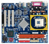
GA-8I865GVME DDR1 DDR2 CLR_CMOS GA-8I865GVME Motherboard Layout VGA COMA KB_MS CPU_FAN ATX LPT ATX_12V Socket 478 R_USB LAN USB AUDIO LPC47M997 F_AUDIO EP82562G CD_IN CODEC FDD SPDIF_IO Intel 865GV BIOS PCI1 IDE2 IDE1 SATA1 Intel ICH5 PCI2 SATA0 PCI3 PWR_LED BATTERY - Gigabyte GA-8I865GVME | User Manual - Page 7
Block Diagram VGA PCI Bus EP82562G Pentium 4 Socket 478 CPU CPUCLK+/-(133/200MHz) Host Interface Intel 865GV GMCH DDR 400/333/266MHz DIMM Dual Channel Memory HCLK (133/200MHz) GMCHCLK (66MHz) 66MHz 33MHz 14.318MHz 48MHz BIOS Intel 2 Serial ATA ICH5 ATA33/66/100 IDE Channels 3 PCI PCICLK - Gigabyte GA-8I865GVME | User Manual - Page 8
- 8 - - Gigabyte GA-8I865GVME | User Manual - Page 9
instructions below: 1. Please turn off the computer and unplug its power cord. 2. When handling the motherboard motherboard. Installation Notices 1. Prior to installation, please do not remove the stickers on the motherboard the motherboard or or have a problem related to the the user manual. 3. Damage - Gigabyte GA-8I865GVME | User Manual - Page 10
detection Š Use of licensed AWARD BIOS Š Supports Q-Flash Š Supports @BIOS Š Supports EasyTune 5 (Note) Š Over clock via BIOS (CPU/ AGP/ DDR/ PCI) Š Micro ATX form factor; 24.4cm x 21.0cm (Note) EasyTune 5 functions may vary depending on different motherboards. GA-8I865GVME Motherboard - 10 - - Gigabyte GA-8I865GVME | User Manual - Page 11
following conditions: 1. Please make sure that the motherboard supports the CPU. 2. Please take note of the one the proper specifications, please do so according to your hardware specifications including An Intel® Chipset that supports HT Technology - BIOS: A BIOS that supports HT Technology and has - Gigabyte GA-8I865GVME | User Manual - Page 12
Please refer to the heat sink manual for detailed installation instructions). Fig.2 Please connect the heat sink power connector to the CPU_FAN connector located on the motherboard so that the heat sink can or using extreme care when removing the heat sink. GA-8I865GVME Motherboard - 12 - - Gigabyte GA-8I865GVME | User Manual - Page 13
only one direction. If you are unable to insert the module, please switch the direction. The motherboard supports DDR memory modules, whereby BIOS will automatically detect memory capacity and specifications. Memory modules are designed so that they can be inserted only in one direction. The memory - Gigabyte GA-8I865GVME | User Manual - Page 14
memory of the same storage capacity in order to use dual channel memory and for BIOS to detect all the DDR memory modules. The following table is for Dual Channel Technology combination: (DS: Double Side, SS: Single Side) 2 memory modules DDR 1 DS/SS DDR 2 DS/SS GA-8I865GVME Motherboard - 14 - - Gigabyte GA-8I865GVME | User Manual - Page 15
the related expansion card's instruction document before install the expansion Press the expansion card firmly into expansion slot in motherboard. 4. Be sure the metal contacts on the BIOS utility of expansion card from BIOS. 8. Install related driver from the operating system. Installing a AGP VGA - Gigabyte GA-8I865GVME | User Manual - Page 16
supports USB controller. If your OS does not support USB controller, please contact OS ven dor for possible patch or driver upgrade. For more information please contact your OS or device(s) vendors. LAN audio software to configure 2-/4-/6-channel audio functioning. GA-8I865GVME Motherboard - 16 - - Gigabyte GA-8I865GVME | User Manual - Page 17
English 1-7 Connectors Introduction 1 3 2 6 11 7 15 12 9 10 13 5 4 14 8 1) ATX_12V 2) ATX (Power Connector) 3) CPU_FAN 4) SYS_FAN 5) FDD 6) IDE1 / IDE2 7) SATA0 / SATA1 8) PWR_LED 9) BATTERY 10) F_PANEL 11) F_AUDIO 12) CD_IN 13) SPDIF_IO 14) F_USB1 / F_USB2 15) CLR_CMOS - 17 - - Gigabyte GA-8I865GVME | User Manual - Page 18
properly installed. Align the power connector with its proper location on the motherboard and connect tightly. The ATX_12V power connector mainly supplies power to the CPU. If the ATX_12V power connector is not ) 15 GND 16 GND 17 GND 18 -5V 19 +5V 20 +5V GA-8I865GVME Motherboard - 18 - - Gigabyte GA-8I865GVME | User Manual - Page 19
connector is used to connect the FDD cable while the other end of the cable connects to the FDD drive. The types of FDD drives supported are: 360KB, 720KB, 1.2MB, 1.44MB and 2.88MB. Please connect the red power connector wire to the pin1 position. 2 34 1 33 - 19 - Hardware Installation - Gigabyte GA-8I865GVME | User Manual - Page 20
(for information on settings, please refer to the instructions located on the IDE device). 40 39 2 BIOS setting for the Serial ATA and install the proper driver in order to work properly. Pin No. Definition 1 GND 7 1 2 TXP 3 TXN 4 GND 5 RXN 6 RXP 7 GND GA-8I865GVME Motherboard - Gigabyte GA-8I865GVME | User Manual - Page 21
is incorrectly replaced. Replace only with the same or equivalent type recommended by the manufacturer. Dispose of used batteries according to the manufacturer's instructions. If you want to erase CMOS... 1. Turn off the computer and unplug the power cord. 2. Take out the battery gently and put it - Gigabyte GA-8I865GVME | User Manual - Page 22
Close: Power On/Off Pin 1: VCC(+) Pin 2- Pin 3: NC Pin 4: Data(-) Pin 1: LED anode(+) Pin 2: LED cathode(-) Open: Normal Operation Close: Reset Hardware System NC GA-8I865GVME Motherboard - 22 - - Gigabyte GA-8I865GVME | User Manual - Page 23
To find out if the chassis you are buying support front audio connector, please contact your dealer. Please note, you can have the alternative of using front audio connector or of using rear audio connector to play sound. 9 1 10 2 Pin No. 1 2 3 4 5 6 7 8 9 10 Definition MIC GND MIC_BIAS Power - Gigabyte GA-8I865GVME | User Manual - Page 24
(SPDIF In / Out Connector) The SPDIF output is capable of providing digital audio to external speakers or compressed AC3 data to an external Dolby Digital Decoder. Use 9 2 Power 3 USB DX- 4 USB Dy- 5 USB DX+ 6 USB Dy+ 7 GND 8 GND 9 No Pin 10 NC GA-8I865GVME Motherboard - 24 - - Gigabyte GA-8I865GVME | User Manual - Page 25
English 15) CLR_CMOS (Clear CMOS) You may clear the CMOS data to its default values by this jumper. To clear CMOS, temporarily short 1-2 pin. Default doesn't include the "Shunter" to prevent from improper use this jumper. Open: Normal 1 Short: Clear CMOS 1 - 25 - Hardware Installation - Gigabyte GA-8I865GVME | User Manual - Page 26
English GA-8I865GVME Motherboard - 26 - - Gigabyte GA-8I865GVME | User Manual - Page 27
BIOS, either Gigabyte's Q-Flash or @BIOS utility can be used. Q-Flash allows the user to quickly and easily update or backup BIOS without entering the operating system. @BIOS is a Windows-based utility that does not require users to boot to DOS before upgrading BIOS but directly download and update - Gigabyte GA-8I865GVME | User Manual - Page 28
and may differ from the exact settings for your motherboard. The Main Menu (For example: BIOS Ver. : E5) Once you enter Award BIOS CMOS Setup Utility, the Main Menu (as figure below) will appear on the parameters which the system would be in safe configuration. GA-8I865GVME Motherboard - 28 - - Gigabyte GA-8I865GVME | User Manual - Page 29
system. „ Save & Exit Setup Save CMOS value settings to CMOS and exit setup. „ Exit Without Saving Abandon all CMOS value changes and exit setup. - 29 - BIOS Setup - Gigabyte GA-8I865GVME | User Manual - Page 30
` IDE Channel 3 Master Drive A Drive B Floppy 3 Mode Support Halt On [None] [None] [None] [None] [None] week, from Sun to Sat, determined by the BIOS and is display only Month The month, Jan. system start up. Manual User can manually input the correct settings GA-8I865GVME Motherboard - 30 - - Gigabyte GA-8I865GVME | User Manual - Page 31
byte capacity 1.44M, 3.5" 3.5 inch double-sided drive; 1.44M byte capacity. 2.88M, 3.5" 3.5 inch double-sided drive; 2.88M byte capacity. Floppy 3 Mode Support the motherboard, or 640K for systems with 640K or more memory installed on the motherboard. Extended Memory The BIOS determines how - Gigabyte GA-8I865GVME | User Manual - Page 32
(C) 1984-2005 Award Software Advanced BIOS Features ` Hard Disk Boot Priority First USB-HDD Select your boot device priority by USB-HDD. LAN Select your boot device priority by LAN. Disabled Select your boot device priority by Disabled. Password the prompt. GA-8I865GVME Motherboard - 32 - - Gigabyte GA-8I865GVME | User Manual - Page 33
mode supported. (Default VGA frame buffer. 1MB Set on-chip frame buffer size to 1MB. 4MB Set on-chip frame buffer size to 4MB. 8MB Set on-chip frame buffer size to 8MB. 16MB Set on-chip frame buffer size to 16MB. (Default value) 32MB Set on-chip frame buffer size to 32MB. - 33 - BIOS - Gigabyte GA-8I865GVME | User Manual - Page 34
Support USB Mouse Support AC97 Audio Onboard H/W LAN ) Manual Set SATA mode manually from supported by Windows XP or later. (Default value) SATA Port1 Set SATA controller to native mode(Serial ATA mode - SATA Port 1). This mode is only supported by Windows XP or later. GA-8I865GVME Motherboard - Gigabyte GA-8I865GVME | User Manual - Page 35
Support Enabled Enable USB mouse support. Disabled Disable USB mouse support. (Default value) AC97 Audio Auto Disabled Auto detect AC97 audio function. (Default value) Disable AC97 audio function. Onboard H/W LAN Enabled Enable onboard H/W LAN Port 1 Auto BIOS will automatically setup - Gigabyte GA-8I865GVME | User Manual - Page 36
as Enhanced Parallel Port 1.7 and ECP mode. ECP Mode Use DMA 3 Set ECP Mode Use DMA to 3. (Default value) 1 Set ECP Mode Use DMA to 1. GA-8I865GVME Motherboard - 36 - - Gigabyte GA-8I865GVME | User Manual - Page 37
An incoming call via modem can awake the system from any suspend state or an input signal comes from the other client server on the LAN can awake the system from any suspend state. Disabled Disable Modem Ring On / Wake On - Gigabyte GA-8I865GVME | User Manual - Page 38
) Set IRQ 3,4,5,7,9,10,11,12,14,15 to PCI 2. Auto assign IRQ to PCI 3. (Default value) Set IRQ 3,4,5,7,9,10,11,12,14,15 to PCI 3. GA-8I865GVME Motherboard - 38 - - Gigabyte GA-8I865GVME | User Manual - Page 39
's voltage status automatically. Current CPU/SYSTEM FAN Speed (RPM) Detect CPU/SYSTEM Fan speed status automatically. ESC: Exit F1: General Help F7: Optimized Defaults - 39 - BIOS Setup - Gigabyte GA-8I865GVME | User Manual - Page 40
) for FSB(Front Side Bus) frequency=533Mhz, 2.0 Memory Frequency = Host clock x 2. 2.5 Memory Frequency = Host clock x 2.5. Auto Set Memory frequency by DRAM SPD data. (Default value) GA-8I865GVME Motherboard - 40 - - Gigabyte GA-8I865GVME | User Manual - Page 41
depend on CPU Host Frequency(Mhz) and Memory Frequency For. AGP/PCI/SRC Frequency (Mhz) The values depend on AGP/PCI/SRC Fixed item. - 41 - BIOS Setup - Gigabyte GA-8I865GVME | User Manual - Page 42
Standard CMOS Features Load Fail-Safe Defaults ` Advanced BIOS Features Load Optimized Defaults ` Integrated Peripherals Set Supervisor Password this field loads the factory defaults for BIOS and Chipset Features which the system automatically detects. GA-8I865GVME Motherboard - 42 - - Gigabyte GA-8I865GVME | User Manual - Page 43
the system will boot and you can enter Setup freely. The BIOS Setup program allows you to specify two separate passwords: SUPERVISOR PASSWORD and only basic items. If you select "System" at "Password Check" in Advance BIOS Features Menu, you will be prompted for the password every time the system is - Gigabyte GA-8I865GVME | User Manual - Page 44
-2005 Award Software ` Standard CMOS Features Load Fail-Safe Defaults ` Advanced BIOS Features Load Optimized Defaults ` Integrated Peripherals Set Supervisor Password ` Power Management without saving to RTC CMOS. Type "N" will return to Setup Utility. GA-8I865GVME Motherboard - 44 - - Gigabyte GA-8I865GVME | User Manual - Page 45
will continue to install other drivers. System will reboot automatically after install the drivers, afterward you can install others application. For USB2.0 driver support under Windows XP operating system, please use Windows Service Pack. After install Windows Service Pack, it will show a question - Gigabyte GA-8I865GVME | User Manual - Page 46
English 3-2 Software Application This page displays all the tools that GIGABYTE developed and some free software. You can click an item to install it. 3-3 Software Information This page lists the contents of software and drivers in this CD-title. GA-8I865GVME Motherboard - 46 - - Gigabyte GA-8I865GVME | User Manual - Page 47
English 3-4 Hardware Information This page lists all device you have for this motherboard. 3-5 Contact Us Please see the last page for details. - 47 - Drivers Installation - Gigabyte GA-8I865GVME | User Manual - Page 48
English GA-8I865GVME Motherboard - 48 - - Gigabyte GA-8I865GVME | User Manual - Page 49
Mode" & "Advance Mode" 7. Display screen 8. Function display LEDs 9. GIGABYTE Logo 10. Help button 11. Exit or Minimize button Description Enters the of CPU frequency Shows the current functions status Log on to GIGABYTE website Display EasyTuneTM 5 Help file Quit or Minimize EasyTuneTM 5 - Gigabyte GA-8I865GVME | User Manual - Page 50
Supporting Microsoft operating systems including Windows XP 64M bytes of system memory 3. VESA-supported VGA BIOS v6.00PG, An Energy Star Ally Copyright (C) 1984-2005, Award Software, Inc. Intel 945 BIOS for 8I945GME E7 . . . . :BIOS drivers as well as software. GA-8I865GVME Motherboard - 50 - - Gigabyte GA-8I865GVME | User Manual - Page 51
. 5. Xpress Recovery2 supports only PATA hard disks and not SATA hard disks on the following motherboards (As this is a BIOS-related issue, it can be solved by BIOS update) GA-K8U GA-K8U-9 GA-K8NXP-SLI GA-K8N Ultra-SLI GA-K8N Pro-SLI GA-K8NXP-9 GA-K8N Ultra-9 GA-K8NF-9 (PCB Ver. 1.0) GA-K8NE (PCB - Gigabyte GA-8I865GVME | User Manual - Page 52
Part One. If your motherboard has single-BIOS, please refer to Part Two. Part One: Updating BIOS with Q-FlashTM Utility on Dual BIOS Motherboards. Some of Gigabyte motherboards are equipped with dual BIOS. In the BIOS menu of the motherboards supporting Q-Flash and Dual BIOS, the Q-Flash utility and - Gigabyte GA-8I865GVME | User Manual - Page 53
Backup Load Default Settings Save Settings to CMOS Q-Flash Utility Load Main BIOS from Floppy Load Backup BIOS from Floppy Save Main BIOS to Floppy Save Backup BIOS to Floppy Enter : Run :Move ESC:Reset F10:Power Off Dual BIOS utility bar Q-FlashTM utility title bar Action bar Task menu for - Gigabyte GA-8I865GVME | User Manual - Page 54
Save Main BIOS to Floppy Save Backup BIOS to Floppy Enter : Run :Move ESC:Reset F10:Power Off Do not turn off power or reset your system at this stage!! After BIOS file is read, you'll see a confirmation dialog box asking you "Are you sure to update BIOS?" GA-8I865GVME Motherboard - 54 - Gigabyte GA-8I865GVME | User Manual - Page 55
displayed. Please do not take out the floppy disk when it begins flashing BIOS. 4. Press any keys to return to the Q-Flash menu when the BIOS updating procedure is completed. Dual BIOS Utility Boot From Main Bios Main ROM Type/Size SST 49LF004A Backup ROM Type/Size SST 49LF004A 512K 512K Wide - Gigabyte GA-8I865GVME | User Manual - Page 56
to save and exit. Part Two: Updating BIOS with Q-FlashTM Utility on Single-BIOS Motherboards. This part guides users of single-BIOS motherboards how to update BIOS using the Q-FlashTM utility. CMOS Language F10: Save & Exit Setup Time, Date, Hard Disk Type... GA-8I865GVME Motherboard - 56 - - Gigabyte GA-8I865GVME | User Manual - Page 57
Q-FlashTM utility Enter : Run Keep DMI Data Enable Update BIOS from Floppy Save BIOS to Floppy :Move ESC:Reset F10:Power Off Action download one BIOS file to the floppy disk so only one BIOS file, 8GE800.F4, is listed. Please confirm again you have the correct BIOS file for your motherboard - Gigabyte GA-8I865GVME | User Manual - Page 58
03/18/2003-I845GE-6A69YG01C-00 6. Press Del to enter BIOS menu after system reboots and "Load BIOS Fail-Safe Defaults". See how to Load BIOS Fail-Safe Defaults, please kindly refer to Step 6 to 7 in Part One. Congratulation!! You have updated BIOS successfully!! GA-8I865GVME Motherboard - 58 - - Gigabyte GA-8I865GVME | User Manual - Page 59
Select @BIOSTM sever. d. Select the exact model name on your motherboard. e. System will automatically download and update the BIOS. II. Update BIOS NOT through Internet: a. Do not click "Internet Update" icon. b. Click "Update New BIOS". c. Please select "All Files" in dialog box while opening the - Gigabyte GA-8I865GVME | User Manual - Page 60
@BIOSTM server, please go onto Gigabyte's website for downloading and updating it according to method II. IV. Please note that any interruption during updating will cause system unbooted. V. Do not use @BIOS and C.O.M. (Corporate Online Management) at the same time. GA-8I865GVME Motherboard - 60 - - Gigabyte GA-8I865GVME | User Manual - Page 61
Windows XP) Stereo Speakers Connection and Settings: We recommend that you use the speaker with amplifier to acquire the best sound effect if the stereo output is applied. STEP 1: Connect the stereo speakers or earphone to "Line Out". Line Out STEP 2: Following installation of the audio driver, you - Gigabyte GA-8I865GVME | User Manual - Page 62
Following installation of the audio driver, you'll find a Sound Effect icon on the audio configuration. Note: When the "Environment" setting is "None", the sound would be performed as stereo mode (2 channels output). Please select the other settings for 4 channels output. GA-8I865GVME Motherboard - Gigabyte GA-8I865GVME | User Manual - Page 63
to "Line Out", the Rear Speakers to "Line In", and the Center/Subwoofer Speakers to "MIC In". STEP 2: Following installation of the audio driver, you'll find a Sound Effect icon on the lower right hand taskbar. Click the icon to select the function. Line In (Rear Speaker Out) Line Out (Front - Gigabyte GA-8I865GVME | User Manual - Page 64
Output Device (Optional Device) A "SPDIF output" connector is available on the motherboard. Cable with rear bracket could link to the "SPDIF output" connector ( and fix it with screw. 2. Connect SPDIF device to the motherboard. 3. Connect SPDIF to the SPDIF decoder. GA-8I865GVME Motherboard - 64 - - Gigabyte GA-8I865GVME | User Manual - Page 65
.1 or later version before to enable Jack-Sensing support for Windows 2000. Jack-Sensing includes 2 parts: AUTO and MANUAL. (Following pictures are in Windows XP): Introduction of audio connectors You may connect CDROM, Walkman or others audio input devices to Line In jack, speakers, earphone - Gigabyte GA-8I865GVME | User Manual - Page 66
English If you set wrong with the connectors, the warning message will come out as right picture. Manual setting: If the device picture shows different from what you set, please press "Manual Selection" to set. GA-8I865GVME Motherboard - 66 - - Gigabyte GA-8I865GVME | User Manual - Page 67
Troubleshooting Below is a collection of general asked questions. To check general asked questions based on a specific motherboard model, please log on to http://www.gigabyte.com.tw Question 1: I cannot see some options that were included in previous BIOS after updating BIOS in the manual. If your - Gigabyte GA-8I865GVME | User Manual - Page 68
English GA-8I865GVME Motherboard - 68 - - Gigabyte GA-8I865GVME | User Manual - Page 69
- 69 - Appendix English - Gigabyte GA-8I865GVME | User Manual - Page 70
English GA-8I865GVME Motherboard - 70 - - Gigabyte GA-8I865GVME | User Manual - Page 71
WEB address : http://www.gigabyte.de Japan NIPPON GIGA-BYTE CORPORATION WEB address : http://www.gigabyte.co.jp Singapore GIGA-BYTE SINGAPORE PTE. LTD. Tech. Support : http://tw.giga-byte.com/TechSupport/ServiceCenter.htm Non-Tech. Support(Sales/Marketing) : http://ggts.gigabyte.com.tw/nontech.asp - Gigabyte GA-8I865GVME | User Manual - Page 72
.gigabyte.cz Romania Representative Office Of GIGA-BYTE Technology Co., Ltd. in Romania Tech. Support : http://tw.giga-byte.com/TechSupport/ServiceCenter.htm Non-Tech. Support(Sales/Marketing) : http://ggts.gigabyte.com.tw/nontech.asp WEB address: http://www.gigabyte.com.ro GA-8I865GVME Motherboard
-
 1
1 -
 2
2 -
 3
3 -
 4
4 -
 5
5 -
 6
6 -
 7
7 -
8
-
9
-
10
-
11
-
12
-
13
-
14
-
15
-
16
-
17
-
18
-
19
-
20
-
21
-
22
-
23
-
24
-
25
-
26
-
27
-
28
-
29
-
30
-
31
-
32
-
33
-
34
-
35
-
36
-
37
-
38
-
39
-
40
-
41
-
42
-
43
-
44
-
45
-
46
-
47
-
48
-
49
-
50
-
51
-
52
-
53
-
54
-
55
-
56
-
57
-
58
-
59
-
60
-
61
-
62
-
63
-
64
-
65
-
66
-
67
-
68
-
69
-
70
-
71
-
72
 |
 |

GA-8I865GVME
Intel
®
Pentium
®
4 Processor Motherboard
User's Manual
Rev. 1003
12ME-865GVME-1003R
*
The WEEE marking on the product indicates this product must not be disposed of with user's other household waste
and must be handed over to a designated collection point for the recycling of waste electrical and electronic equipment!!
*
The WEEE marking applies only in European Union's member states.