Gigabyte GA-8I865PE775-G-RH Manual
Gigabyte GA-8I865PE775-G-RH Manual
 |
View all Gigabyte GA-8I865PE775-G-RH manuals
Add to My Manuals
Save this manual to your list of manuals |
Gigabyte GA-8I865PE775-G-RH manual content summary:
- Gigabyte GA-8I865PE775-G-RH | Manual - Page 1
GA-8I865PE775-G-RH Intel® CoreTM 2 Extreme dual-core / CoreTM 2 Duo Intel® Pentium® D / Intel® Pentium® 4 LGA775 Processor Motherboard User's Manual Rev. 4901 12ME-8I865PETG-4901R * The WEEE marking on the product indicates this product must not be disposed of with user's other household waste and - Gigabyte GA-8I865PE775-G-RH | Manual - Page 2
Motherboard GA-8I865PE775-G-RH Jan. 12, 2007 Motherboard GA-8I865PE775-G-RH Jan. 12, 2007 - Gigabyte GA-8I865PE775-G-RH | Manual - Page 3
the product. „ For detailed product information and specifications, please carefully read the "User's Manual." „ For detailed information related to Gigabyte's unique features, please go to the "Technology Guide" section on Gigabyte's website to read or download the information you need. For more - Gigabyte GA-8I865PE775-G-RH | Manual - Page 4
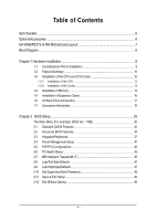
Table of Contents ItemChecklist ...6 OptionalAccessories ...6 GA-8I865PE775-G-RH Motherboard Layout 7 Block Diagram ...8 Chapter 1 Hardware Installation 9 1-1 Considerations Prior to Installation 9 1-2 Feature Summary 10 1-3 Installation of the CPU and CPU Cooler 12 1-3-1 Installation of the - Gigabyte GA-8I865PE775-G-RH | Manual - Page 5
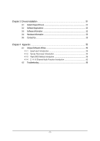
Information 53 3-5 Contact Us ...53 Chapter 4 Appendix 55 4-1 Unique Software Utilities 55 4-1-1 EasyTune 5 Introduction 55 4-1-2 Xpress Recovery2 Introduction 56 4-1-3 Flash BIOS Method Introduction 58 4-1-4 2 / 4 / 6 Channel Audio Function Introduction 62 4-2 Troubleshooting 68 - 5 - - Gigabyte GA-8I865PE775-G-RH | Manual - Page 6
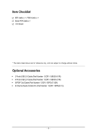
Š 2 Ports USB 2.0 Cable (Part Number: 12CR1-1UB030-51/R) Š 4 Ports USB 2.0 Cable (Part Number: 12CR1-1UB030-21/R) Š S/PDIF Out Cable (Part Number: 12CR1-1SPOUT-02R) Š 6-Channel Audio Combo Kit (Part Number: 12CR1-1SPAUD-12) - 6 - - Gigabyte GA-8I865PE775-G-RH | Manual - Page 7
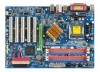
RH Motherboard Layout KB_MS LGA775 ATX_12V CPU_FAN COMA LPT GA-8I865PE775 -G-RH DDR1 DDR2 DDR3 DDR4 ATX COMB USB USB_LAN AUDIO F_AUDIO Intel® 865G/865PE RTL 8110SC CODEC CD_IN IT8718 AGP SUR_CEN AUX_IN CI SPDIF_O BATTERY PCI1 CLR_CMOS Intel® ICH5 PCI2 IDE1 IDE2 FDD PCI3 PCI4 BIOS - Gigabyte GA-8I865PE775-G-RH | Manual - Page 8
Block Diagram AGP 8X/4X LGA775 Processor CPU CLK+/-(200/133 MHz) Host Interface Intel® 865G/865PE DDR 400/333/266 MHz DIMM Dual Channel Memory PCI Bus RTL 8110SC RJ45 Intel® ICH5 5 PCI PCI CLK (33 MHz) MIC Line-Out Line-In CODEC 8 USB Ports BIOS 2 Serial ATA ATA-33/66/100 - Gigabyte GA-8I865PE775-G-RH | Manual - Page 9
instructions below: 1. Please turn off the computer and unplug its power cord. 2. When handling the motherboard , avoid touching any metal leads or connectors. 3. It is best to wear an electrostatic discharge (ESD) cuff when handling electronic components (CPU motherboard problem manual - Gigabyte GA-8I865PE775-G-RH | Manual - Page 10
connector Š 1 front audio connector Š 1 CD In connector Š 1 AUX In connector Š 1 Surround Center connector Š 1 S/PDIF Out connector Š 1 power LED connector Š 2 USB 2.0/1.1 connectors for additional 4 ports by cables Š 1 Chassis Intrusion connector GA-8I865PE775-G-RH Motherboard - 10 - - Gigabyte GA-8I865PE775-G-RH | Manual - Page 11
CPU smart fan control BIOS Š 1 4 Mbit flash ROM Š Use of licensed AWARD BIOS Š PnP 1.0a, DMI 2.0, SM BIOS 2.3, ACPI 1.0b Additional Features Š Supports @BIOS Š Supports Download Center Š Supports Q-Flash Š Supports EasyTune (only supports CPU support information, please go to GIGABYTE's - Gigabyte GA-8I865PE775-G-RH | Manual - Page 12
the socket in a straight and downwards motion. Avoid twisting or bending motions that might cause damage to the CPU during installation.) GA-8I865PE775-G-RH Motherboard - 12 - Fig. 4 Once the CPU is properly inserted, please replace the load plate and push the metal lever back into its original - Gigabyte GA-8I865PE775-G-RH | Manual - Page 13
make sure the Male and Female push pin are joined closely. (for detailed installation instructions, please refer to the CPU cooler installation section of the user manual) Fig. 5 Please check the back of motherboard after installing. If the push pin is inserted as the picture, the installation is - Gigabyte GA-8I865PE775-G-RH | Manual - Page 14
the module, please switch the direction. The motherboard supports DDR memory modules, whereby BIOS will automatically detect memory capacity and specifications. Memory modules are designed so that they can the DIMM module. DDR memory module Fig. 1 Fig. 2 GA-8I865PE775-G-RH Motherboard - 14 - - Gigabyte GA-8I865PE775-G-RH | Manual - Page 15
6.4 GB/s. GA-8I865PE775-G-RH includes 4 DIMM sockets, and each Channel has two DIMM sockets as following: Channel A : DDR 1, DDR 2 Channel B : DDR 3, DDR 4 If you want to operate the Dual Channel Technology, please note the following explanations due to the limitation of Intel chipset specifications - Gigabyte GA-8I865PE775-G-RH | Manual - Page 16
card's instruction document before BIOS utility of expansion card from BIOS. 8. Install related driver VGA card. Please align the VGA card to the onboard AGP slot and press firmly down on the slot. Make sure your VGA card is locked by the small white-drawable bar. GA-8I865PE775-G-RH Motherboard - Gigabyte GA-8I865PE775-G-RH | Manual - Page 17
USB controller. If your OS does not support USB controller, please contact OS vendor for possible patch or driver upgrade. For more information please contact your OS or device(s) vendors. LAN Port The provided Internet connection is Gigabit Ethernet (PCI Express Gigabit), providing data transfer - Gigabyte GA-8I865PE775-G-RH | Manual - Page 18
/ IDE2 6) FDD 7) SATA0 / SATA1 8) F_PANEL 9) PWR_LED 10) F_AUDIO 11) CD_IN 12) AUX_IN 13) SUR_CEN 14) SPDIF_O 15) F_USB1 / F_USB2 16) CI 17) CLR_CMOS 18) BATTERY GA-8I865PE775-G-RH Motherboard - 18 - - Gigabyte GA-8I865PE775-G-RH | Manual - Page 19
all components and devices are properly installed. Align the power connector with its proper location on the motherboard and connect tightly. The ATX_12V power connector mainly supplies power to the CPU. If the ATX_12V power connector is not connected, the system will not start. Caution! Please use - Gigabyte GA-8I865PE775-G-RH | Manual - Page 20
to connect the CPU/system fan cable to the CPU_FAN/SYS_FAN connector to prevent the CPU/system from overheating instructions located on the IDE device). Before attaching the IDE cable, please take note of the foolproof groove in the IDE connector. 40 39 40 39 GA-8I865PE775-G-RH Motherboard - Gigabyte GA-8I865PE775-G-RH | Manual - Page 21
of the cable connects to the FDD drive. The types of FDD drives supported are: 360 KB, 720 KB, 1.2 MB, 1.44 MB and 2. can provide up to 150 MB/s transfer rate. Please refer to the BIOS setting for the Serial ATA and install the proper driver in order to work properly. 7 1 SATA0 7 1 SATA1 Pin - Gigabyte GA-8I865PE775-G-RH | Manual - Page 22
1: Power Pin 2- Pin 3: NC Pin 4: Data(-) Open: Normal Close: Reset Hardware System Open: Normal Close: Power On/Off Pin 1: LED anode(+) Pin 2: LED cathode(-) NC GA-8I865PE775-G-RH Motherboard - 22 - - Gigabyte GA-8I865PE775-G-RH | Manual - Page 23
the MB header. To find out if the chassis you are buying support front audio connector, please contact your dealer.Please note, you can have the alternative of using front audio connector or of using rear audio connector to play sound. Pin No. Definition 1 MIC 2 GND 1 2 3 MIC_BIAS 4 POWER - Gigabyte GA-8I865PE775-G-RH | Manual - Page 24
or DVD-ROM audio out to the connector. Pin No. Definition 1 1 CD-L 2 GND 3 GND 4 CD-R 12) AUX_IN (AUX In Connector) Connect other device (such as PCI TV Tunner audio out) to the connector. Pin No. Definition 1 1 AUX-L 2 GND 3 GND 4 AUX-R GA-8I865PE775-G-RH Motherboard - 24 - - Gigabyte GA-8I865PE775-G-RH | Manual - Page 25
6 Definition SUR OUTL SUR OUTR GND No Pin CENTER_OUT BASS_OUT 14) SPDIF_O (S/PDIF Out Connector) The S/PDIF output is capable of providing digital audio to external speakers or compressed AC3 data to an external Dolby Digital Decoder. Use this feature only when your stereo system has digital input - Gigabyte GA-8I865PE775-G-RH | Manual - Page 26
Intrusion, Case Open) This 2-pin connector allows your system to detect if the chassis cover is removed. You can check the "Case Opened" status in BIOS Setup. Pin No. Definition 1 1 Signal 2 GND GA-8I865PE775-G-RH Motherboard - 26 - - Gigabyte GA-8I865PE775-G-RH | Manual - Page 27
is incorrectly replaced. Replace only with the same or equivalent type recommended by the manufacturer. Dispose of used batteries according to the manufacturer's instructions. If you want to erase CMOS... 1. Turn OFF the computer and unplug the power cord. 2. Take out the battery gently and put it - Gigabyte GA-8I865PE775-G-RH | Manual - Page 28
English GA-8I865PE775-G-RH Motherboard - 28 - - Gigabyte GA-8I865PE775-G-RH | Manual - Page 29
BIOS, either GIGABYTE's Q-Flash or @BIOS utility can be used. Q-Flash allows the user to quickly and easily update or backup BIOS without entering the operating system. @BIOS is a Windows-based utility that does not require users to boot to DOS before upgrading BIOS but directly download and update - Gigabyte GA-8I865PE775-G-RH | Manual - Page 30
BIOS Setup when somehow the system is not stable as usual. This action makes the system reset to the default settings for stability. 3. The BIOS Setup menus described in this chapter are for reference only and may differ from the exact settings for your motherboard. GA-8I865PE775-G-RH Motherboard - Gigabyte GA-8I865PE775-G-RH | Manual - Page 31
setup page includes all the items in standard compatible BIOS. „ Advanced BIOS Features This setup page includes all the items of voltage, fan, speed. „ MB Intelligent Tweaker(M.I.T.) This setup page is control CPU clock and frequency ratio. „ Load Fail-Safe Defaults Fail-Safe Defaults indicates - Gigabyte GA-8I865PE775-G-RH | Manual - Page 32
Floppy 3 Mode Support [1.44M, Manual User can manually BIOS to automatically detect IDE/SATA devices during POST(default) • None Select this if no IDE/SATA devices are used and the system will skip the automatic detection step and allow for faster system start up. GA-8I865PE775-G-RH Motherboard - Gigabyte GA-8I865PE775-G-RH | Manual - Page 33
M byte capacity. Floppy 3 Mode Support (for Japan Area) Disabled Drive A be prompted. Whenever the BIOS detects a non-fatal error the BIOS. Base Memory The POST of the BIOS will motherboard, or 640 K for systems with 640 K or more memory installed on the motherboard. Extended Memory The BIOS - Gigabyte GA-8I865PE775-G-RH | Manual - Page 34
If no LAN cable is attached to the motherboard, the Status fields of all four pairs of wires will show Open and the Length fields show 0.0m, as shown in the figure above. (Note) This item will show up when you install a processor which supports this function. GA-8I865PE775-G-RH Motherboard - 34 - Gigabyte GA-8I865PE775-G-RH | Manual - Page 35
operate at a normal speed of 10/100/1000 Mbps in Windows mode or when the LAN Boot ROM is activated. When a Cable Problem Occurs... If a cable problem occurs on a specified pair of wires, the Status field will show up when you install a processor which supports this function. - 35 - BIOS Setup - Gigabyte GA-8I865PE775-G-RH | Manual - Page 36
function. Virtualization Technology (Note) Enabled Enable Virtualization Technology. (Default value) Disabled Disable this function. (Note) This item will show up when you install a processor which supports this function. GA-8I865PE775-G-RH Motherboard - 36 - - Gigabyte GA-8I865PE775-G-RH | Manual - Page 37
Support USB Mouse Support Legacy USB storage detect AC97 Audio Onboard H/W LAN OnBoard LAN to IDE controller. (Default value) Manual Set SATA mode manually from "SATA Port0 configure as" item mode - SATA Port 0). This mode is only supported by Windows XP or later. (Default value) SATA Port1 - Gigabyte GA-8I865PE775-G-RH | Manual - Page 38
BIOS will scan all USB storage devices. (Default value) Disabled Disable this function. AC97 Audio Auto Disabled Enable onboard AC'97 audio function. (Default value) Disable this function. Onboard H/W LAN Enabled Enable onboard H/W LAN Serial port 1. GA-8I865PE775-G-RH Motherboard - 38 - - Gigabyte GA-8I865PE775-G-RH | Manual - Page 39
English Onboard Serial Port 2 Auto 3F8/IRQ4 2F8/IRQ3 3E8/IRQ4 2E8/IRQ3 BIOS will automatically setup the port 2 address. Enable onboard Serial port 2 and address is 3F8/IRQ4. Enable onboard Serial DMA 3 Set ECP Mode Use DMA to 3. (Default value) 1 Set ECP Mode Use DMA to 1. - 39 - BIOS Setup - Gigabyte GA-8I865PE775-G-RH | Manual - Page 40
any suspend state or an input signal comes from the other client server on the LAN can awake the system from any suspend state. Disabled Disable Modem Ring On / Wake On LAN function. Enabled Enable Modem Ring On / Wake On LAN function. (Default value) GA-8I865PE775-G-RH Motherboard - 40 - - Gigabyte GA-8I865PE775-G-RH | Manual - Page 41
always in "On" state. Memory When AC-power back to the system, the system will return to the Last state before AC-power off. - 41 - BIOS Setup - Gigabyte GA-8I865PE775-G-RH | Manual - Page 42
. PCI4 IRQ Assignment Auto Auto assign IRQ to PCI4. (Default value) 3,4,5,7,9,10,11,12,14,15 Set IRQ 3,4,5,7,9,10,11,12,14,15 to PCI4. GA-8I865PE775-G-RH Motherboard - 42 - - Gigabyte GA-8I865PE775-G-RH | Manual - Page 43
CPU temperature at 80oC / 176oF. 90oC / 194oF Monitor CPU temperature at 90oC / 194oF. Disabled Disable this function. (Default value) CPU/SYSTEM FAN Fail Warning Disabled Enabled Disable the fan fail warning function. (Default value) Enable the fan fail warning function. - 43 - BIOS - Gigabyte GA-8I865PE775-G-RH | Manual - Page 44
option can be used for CPU fans with 3-pin or 4-pin power cables. However, some 4-pin CPU fan power cables are not designed following Intel 4-Wire fans PWM control specifications. With such CPU fans, selecting PWM will not effectively reduce the fan speed. GA-8I865PE775-G-RH Motherboard - 44 - - Gigabyte GA-8I865PE775-G-RH | Manual - Page 45
set "CPU Host Frequency" to 133 MHz. If you use an 800 MHz FSB processor, set "CPU Host Frequency" to 200 MHz. Incorrect using it may cause your system broken. For power End-User use only! (Note) This item will show up when you install a processor which supports this function. - 45 - BIOS Setup - Gigabyte GA-8I865PE775-G-RH | Manual - Page 46
voltage by +0.1V to +0.3V. Incorrect using it may cause your system broken. For power End-User use only! CPU Voltage Control Supports adjustable CPU Vcore from 0.85000V to 2.0000V. (Default value: Normal) Normal CPU Vcore Display your CPU Vcore Voltage. GA-8I865PE775-G-RH Motherboard - 46 - - Gigabyte GA-8I865PE775-G-RH | Manual - Page 47
-Safe Defaults CMOS Setup Utility-Copyright (C) 1984-2007 Award Software ` Standard CMOS Features Load Fail-Safe Defaults ` Advanced BIOS Features Load Optimized Defaults ` Integrated Peripherals Set Supervisor Password ` Power Management Setup Set User Password ` PnP/PCI Configurations - Gigabyte GA-8I865PE775-G-RH | Manual - Page 48
Advance BIOS Features Menu, you will be prompted for the password every time the system is rebooted or any time you try to enter Setup Menu. If you select "Setup" at "Password Check" in Advance BIOS Features Menu, you will be prompted only when you try to enter Setup. GA-8I865PE775-G-RH Motherboard - Gigabyte GA-8I865PE775-G-RH | Manual - Page 49
Exit Setup CMOS Setup Utility-Copyright (C) 1984-2007 Award Software ` Standard CMOS Features Load Fail-Safe Defaults ` Advanced BIOS Features Load Optimized Defaults ` Integrated Peripherals Set Supervisor Password ` Power Management Setup Set User Password ` PnP/PCI Configurations Save - Gigabyte GA-8I865PE775-G-RH | Manual - Page 50
English GA-8I865PE775-G-RH Motherboard - 50 - - Gigabyte GA-8I865PE775-G-RH | Manual - Page 51
XP. (1) Please make sure to install the latest service pack for Windows after OS installation and before installing motherboard drivers. (2) Insert the driver CD that came with your motherboard into your CD-ROM drive, the driver CD will auto start and installation screen will appear. If not, please - Gigabyte GA-8I865PE775-G-RH | Manual - Page 52
English 3-2 Software Applications This page displays all the tools that Gigabyte developed and some free software. You can click an item to install it. 3-3 Software Information This page lists the contents of software and drivers in this CD-title. GA-8I865PE775-G-RH Motherboard - 52 - - Gigabyte GA-8I865PE775-G-RH | Manual - Page 53
English 3-4 Hardware Information This page lists all device you have for this motherboard. 3-5 Contact Us You can also see the last page of this manual for contacts information details. - 53 - Drivers Installation - Gigabyte GA-8I865PE775-G-RH | Manual - Page 54
English GA-8I865PE775-G-RH Motherboard - 54 - - Gigabyte GA-8I865PE775-G-RH | Manual - Page 55
support these Unique Software Utilities, please check your MB features.) 4-1-1 EasyTune 5 Introduction EasyTune 5 presents the most convenient Windows CPU and Memory, 3) Smart-Fan control for managing fan speed control of both CPU of CPU frequency Shows the current functions status Log on to GIGABYTE - Gigabyte GA-8I865PE775-G-RH | Manual - Page 56
data. Supporting Microsoft operating systems including Windows XP of system memory 3. VESA-supported VGA cards How to use the Xpress Intel 865PE AGPSet BIOS for 8I865PE775-G-RH PCB 3.0 &4.X FBB . . . . :BIOS Setup/Q-Flash - Gigabyte GA-8I865PE775-G-RH | Manual - Page 57
Windows 2000, be sure to execute the EnableBigLba.exe program from the driver CD before data backup. 2. It is normal that data backup takes longer time than data restoration. 3. Xpress Recovery2 is compliant with the GPL regulations. 4. On a few motherboards based on Nvidia chipsets, BIOS update - Gigabyte GA-8I865PE775-G-RH | Manual - Page 58
Utility v2.02 Flash Type/Size SST 49LF004A/B 512K Keep DMI Data Enable Update BIOS from Drive Sa0vefilBeI(Os)SfotounDdrive EnteFr l:oRppuyn A HDD 0-0 :Move ESC:Reset :Power Off Total size : 0 F5 : Refresh GA-8I865PE775-G-RH Motherboard Free size : 0 DEL : Delete - 58 - - Gigabyte GA-8I865PE775-G-RH | Manual - Page 59
press ENTER. Make sure again the BIOS file matches your motherboard model. Step 2: The process of system reading the BIOS file from the floppy disk is displayed on the screen. When the message "Are you sure to update BIOS?" appears, press ENTER. The BIOS update will begin and the current process - Gigabyte GA-8I865PE775-G-RH | Manual - Page 60
b. Click "Update New BIOS" c. Please select "All Files" in dialog box while opening the old file. d. Please search for BIOS unzip file, downloading from internet or any other methods (such as: 65pe75g2.FB). e. Complete update process following the instruction. GA-8I865PE775-G-RH Motherboard - 60 - Gigabyte GA-8I865PE775-G-RH | Manual - Page 61
II, be sure that motherboard's model name in BIOS unzip file are the same as your motherboard's. Otherwise, your system won't boot. III. In method I, if the BIOS file you need cannot be found in @BIOSTM server, please go onto Gigabyte's web site for downloading and updating it according to method - Gigabyte GA-8I865PE775-G-RH | Manual - Page 62
audio driver, you'll find a Sound Effect icon on the lower right hand taskbar. Click the icon to select the function. STEP 3: On the AC97 Audio Configuration menu, click the Speaker Configuration tab and select the 2-channel mode for stereo speaker output check box. GA-8I865PE775-G-RH Motherboard - Gigabyte GA-8I865PE775-G-RH | Manual - Page 63
Out," the rear channels to "Line In." STEP 2: After installing the audio driver, you'll find a Sound Effect icon on the lower right hand taskbar. Click the icon to select the function. STEP 3: On the AC97 Audio Configuration menu, click the Speaker Configuration tab and select the 4-channel mode - Gigabyte GA-8I865PE775-G-RH | Manual - Page 64
In Line Out STEP 2: After installing the audio driver, you'll find a Sound Effect icon Audio Configuration menu, click the Speaker Configuration tab and select the 6-channel mode for 5.1 speaker output check box. Clear the Only SURROUND-KIT check box and press OK. GA-8I865PE775-G-RH Motherboard - Gigabyte GA-8I865PE775-G-RH | Manual - Page 65
. It is the best solution if you need 6 channel output, Line In and MIC at the same time. "SURROUND-KIT" is included in the GIGABYTE unique "Audio Combo Kit" as picture. STEP 1: Secure the metal bracket of the"Surround Kit" to the chassis back panel with a screw. STEP 2: Connect the "SURROUND - Gigabyte GA-8I865PE775-G-RH | Manual - Page 66
SUB CENTER. STEP 4: After installing the audio driver, you'll find a Sound Effect icon Audio Output Mode Notes: When the Environment setting is None, the sound would be performed as stereo mode (2-channel output). Please select the other settings for 6 channels output. GA-8I865PE775-G-RH Motherboard - Gigabyte GA-8I865PE775-G-RH | Manual - Page 67
English S/PDIF Output Device (Optional Device) A "S/PDIF output" connector is available on the motherboard. Cable with rear bracket could link to the "S/PDIF output" connector (As picture.) For the further linkage to decoder, rear bracket provides coaxial cable and - Gigabyte GA-8I865PE775-G-RH | Manual - Page 68
English 4-2 Troubleshooting Below is a collection of general asked questions. To check general asked questions based on a specific motherboard model, please log on to http://www.gigabyte.com.tw Question 1: I cannot see some options that were included in previous BIOS after updating BIOS. Why? - Gigabyte GA-8I865PE775-G-RH | Manual - Page 69
- 69 - Appendix English - Gigabyte GA-8I865PE775-G-RH | Manual - Page 70
TEL: +86-29-85531943 FAX: +86-29-85539821 Shenyang TEL: +86-24-83992901 FAX: +86-24-83992909 y India GIGABYTE TECHNOLOGY (INDIA) LIMITED WEB address : http://www.gigabyte.in y Australia GIGABYTE TECHNOLOGY PTY. LTD. WEB address : http://www.gigabyte.com.au GA-8I865PE775-G-RH Motherboard - 70 - - Gigabyte GA-8I865PE775-G-RH | Manual - Page 71
Co., Ltd. in Romania WEB address : http://www.gigabyte.com.ro y Serbia & Montenegro Representative Office Of GIGA-BYTE Technology Co., Ltd. in SERBIA & MONTENEGRO WEB address : http://www.gigabyte.co.yu y GIGABYTE Global Service System To submit a technical or non-technical (Sales/ Marketing - Gigabyte GA-8I865PE775-G-RH | Manual - Page 72
English - 72 -
-
 1
1 -
 2
2 -
 3
3 -
 4
4 -
 5
5 -
 6
6 -
 7
7 -
8
-
9
-
10
-
11
-
12
-
13
-
14
-
15
-
16
-
17
-
18
-
19
-
20
-
21
-
22
-
23
-
24
-
25
-
26
-
27
-
28
-
29
-
30
-
31
-
32
-
33
-
34
-
35
-
36
-
37
-
38
-
39
-
40
-
41
-
42
-
43
-
44
-
45
-
46
-
47
-
48
-
49
-
50
-
51
-
52
-
53
-
54
-
55
-
56
-
57
-
58
-
59
-
60
-
61
-
62
-
63
-
64
-
65
-
66
-
67
-
68
-
69
-
70
-
71
-
72
 |
 |

GA-8I865PE775-G-RH
Intel
®
Core
TM
2 Extreme dual-core / Core
TM
2 Duo
Intel
®
Pentium
®
D / Intel
®
Pentium
®
4
LGA775 Processor Motherboard
User's Manual
Rev. 4901
12ME-8I865PETG-4901R
*
The WEEE marking on the product indicates this product must not be disposed of with user's other household waste
and must be handed over to a designated collection point for the recycling of waste electrical and electronic equipment!!
*
The WEEE marking applies only in European Union's member states.