Gigabyte GA-8I865PEM-775 Manual
Gigabyte GA-8I865PEM-775 Manual
 |
View all Gigabyte GA-8I865PEM-775 manuals
Add to My Manuals
Save this manual to your list of manuals |
Gigabyte GA-8I865PEM-775 manual content summary:
- Gigabyte GA-8I865PEM-775 | Manual - Page 1
GA-8I865PEM-775 Intel® Pentium® 4 LGA775 Processor Motherboard User's Manual Rev. 1001 12ME-I865PEMT-1001 - Gigabyte GA-8I865PEM-775 | Manual - Page 2
Motherboard GA-8I865PEM-775 Dec. 9, 2004 Motherboard GA-8I865PEM-775 Dec. 9, 2004 - Gigabyte GA-8I865PEM-775 | Manual - Page 3
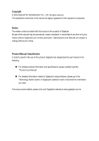
„ For detailed product information and specifications, please carefully read the "Product User Manual". „ For detailed information related to Gigabyte's unique features, please go to the "Technology Guide" section on Gigabyte's website to read or download the information you need. Fore more product - Gigabyte GA-8I865PEM-775 | Manual - Page 4
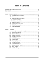
Table of Contents GA-8I865PEM-775 Motherboard Layout 6 Block Diagram ...7 Chapter 1 Hardware Installation 9 1-1 Considerations Prior to Installation 9 1-2 Feature Summary 10 1-3 Installation of the CPU and Heatsink 11 1-3-1 Installation of the CPU 11 1-3-2 - Gigabyte GA-8I865PEM-775 | Manual - Page 5
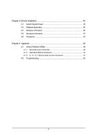
Installation 45 3-1 Install Chipset Drivers 45 3-2 Software Application 46 3-3 Software Information 46 3-4 Hardware Information 47 3-5 Contact Us Introduction 49 4-1-2 Flash BIOS Method Introduction 52 4-1-3 2- / 4- / 5.1- Channel Audio Function Introduction 61 4-2 Troubleshooting 65 - 5 - - Gigabyte GA-8I865PEM-775 | Manual - Page 6
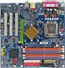
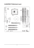
IDE1 GA-8I865PEM-775 Motherboard Layout KB_MS ATX_12V LGA775 CPU_FAN ATX FDD COMA LPT GA-8I865PEM-775 DDR1 DDR2 DDR3 DDR4 IDE2 R_USB USB LAN F_AUDIO LPC47M997 IR AUDIO BIOS AGP SPDIF Marvell 8001 CODEC CD_IN COMB Intel 865PE PCI1 PCI2 PCI3 - Gigabyte GA-8I865PEM-775 | Manual - Page 7
Block Diagram AGP 8X/4X AGPCLK (66MHz) PCI Bus Marvell 8001 RJ45 3 PCI PCICLK (33MHz) MIC Line-Out Line-In LGA775 Processor CPUCLK+/-(133/200MHz) Host Interface DDR 400/333/266MHz DIMM Intel 865PE MCH Dual Channel Memory HCLK (133/200MHz) MCHCLK (66MHz) 66MHz 33MHz 14.318MHz 48MHz BIOS - Gigabyte GA-8I865PEM-775 | Manual - Page 8
- 8 - - Gigabyte GA-8I865PEM-775 | Manual - Page 9
instructions below: 1. Please turn off the computer and unplug its power cord. 2. When handling the motherboard motherboard. Installation Notices 1. Prior to installation, please do not remove the stickers on the motherboard the motherboard or or have a problem related to the the user manual. 3. Damage - Gigabyte GA-8I865PEM-775 | Manual - Page 10
Onboard Marvell 8001 chip (10/100/1000 Mbit) Š 1 RJ 45 port Š ADI AD1888 CODEC Š Supports 2 / 4 / 5.1 channel audio Š Supports Line In (Rear Speaker Out) ; Line Out (Front Speaker Out) ; MIC (Center/Subwoofer Speaker shown as 3.xxGB memory during system startup. GA-8I865PEM-775 Motherboard - 10 - - Gigabyte GA-8I865PEM-775 | Manual - Page 11
comply with the following conditions: 1. Please make sure that the motherboard supports the CPU. 2. Please take note of the one indented corner CPU firmly between your thumb and forefinger, carefully place it into the socket in a straight and downwards motion. Avoid twisting or bending motions that - Gigabyte GA-8I865PEM-775 | Manual - Page 12
joined closely. (for detailed installation instructions, please refer to the heatsink installation section of the user manual) Fig. 5 Please check the back of motherboard after installing. If the push pin or using extreme care when removing the heatsink. GA-8I865PEM-775 Motherboard - 12 - - Gigabyte GA-8I865PEM-775 | Manual - Page 13
to insert the module, please switch the direction. The motherboard supports DDR memory modules, whereby BIOS will automatically detect memory capacity module vertically into the DIMM socket. Then push it down. Fig.2 Close the plastic clip at both edges of the DIMM sockets to lock the DIMM module - Gigabyte GA-8I865PEM-775 | Manual - Page 14
GA-8I865PEM-775 supports the Dual Channel Technology. After operating the Dual Channel Technology, the bandwidth of Memory Bus will double. GA-8I865PEM-775 includes 4 DIMM sockets, and each Channel has two DIMM sockets SS DDR 3 DS/SS X DS/SS DDR 4 X DS/SS DS/SS GA-8I865PEM-775 Motherboard - 14 - - Gigabyte GA-8I865PEM-775 | Manual - Page 15
Read the related expansion card's instruction document before install the expansion 3. Press the expansion card firmly into expansion slot in motherboard. 4. Be sure the metal contacts on the card of expansion card from BIOS. 8. Install related driver from the operating system. Installing a AGP VGA - Gigabyte GA-8I865PEM-775 | Manual - Page 16
interface. Also make sure your OS supports USB controller. If your OS does not support USB controller, please contact OS vendor for possible patch or driver upgrade. For more information please contact software to configure 2-/4-/5.1-channel audio functioning. GA-8I865PEM-775 Motherboard - 16 - - Gigabyte GA-8I865PEM-775 | Manual - Page 17
English 1-7 Connectors Introduction 1 3 2 16 11 13 12 15 1) ATX_12V 2) ATX (Power Connector) 3) CPU_FAN 4) SYS_FAN 5) FDD 6) IDE1 / IDE2 7) SATA0 / SATA1 8) PWR_LED 9) BAT 5 6 9 17 4 7 8 14 10 10) F_PANEL 11) F_AUDIO 12) CD_IN 13) SPDIF 14) F_USB1 / F_USB2 15) COMB 16) IR 17) CLR_CMOS - - Gigabyte GA-8I865PEM-775 | Manual - Page 18
to start. If you use a 24-pin ATX power supply, please remove the small cover on the power connector on the motherboard before plugging in the power cord ; Otherwise, please do not remove it. 42 31 Pin No. 1 2 3 4 GND 20 -5V 21 VCC 22 VCC 23 VCC 24 GND GA-8I865PEM-775 Motherboard - 18 - - Gigabyte GA-8I865PEM-775 | Manual - Page 19
connector is used to connect the FDD cable while the other end of the cable connects to the FDD drive. The types of FDD drives supported are: 360KB, 720KB, 1.2MB, 1.44MB and 2.88MB. Please connect the red power connector wire to the pin1 position. 34 33 2 1 - 19 - Hardware Installation - Gigabyte GA-8I865PEM-775 | Manual - Page 20
and the other as Slave (for information on settings, please refer to the instructions located on the IDE device). 40 39 2 1 7) SATA0 / SATA1 proper driver in order to work properly. Pin No. Definition 7 1 1 GND 2 TXP 3 TXN 4 GND 5 RXN 6 RXP 7 GND GA-8I865PEM-775 Motherboard - Gigabyte GA-8I865PEM-775 | Manual - Page 21
is incorrectly replaced. Replace only with the same or equivalent type recommended by the manufacturer. Dispose of used batteries according to the manufacturer's instructions. If you want to erase CMOS... 1. Turn OFF the computer and unplug the power cord. 2. Remove the battery, wait for 30 seconds - Gigabyte GA-8I865PEM-775 | Manual - Page 22
2- Pin 3: NC Pin 4: Data(-) Open: Normal Operation Close: Reset Hardware System Open: Normal Operation Close: Power On/Off Pin 1: LED anode(+) Pin 2: LED cathode(-) NC GA-8I865PEM-775 Motherboard - 22 - - Gigabyte GA-8I865PEM-775 | Manual - Page 23
assignments for the cable are the same as the pin assignments for the front audio header. To find out if the chassis you are buying support front audio connector, please contact your dealer. Please note, you can have the alternative of using front audio connector or of using rear audio connector - Gigabyte GA-8I865PEM-775 | Manual - Page 24
, please contact your local dealer. Pin No. Definition 1 Power 2 10 2 Power 1 9 3 USB Dx- 4 USB Dy- 5 USB Dx+ 6 USB Dy+ 7 GND 8 GND 9 No Pin 10 NC GA-8I865PEM-775 Motherboard - 24 - - Gigabyte GA-8I865PEM-775 | Manual - Page 25
English 15) COMB (COMB Connector) Be careful with the polarity of the COMB connector. Check the pin assignment carefully while you connect the COMB cable, incorrect connection between the cable and connector will make the device unable to work or even damage it. For optional COMB cable, please - Gigabyte GA-8I865PEM-775 | Manual - Page 26
English 17) CLR_CMOS (Clear CMOS) You may clear the CMOS data to its default values by this jumper. To clear CMOS, temporarily short 1-2 pin. Default doesn't include the "Shunter" to prevent from improper use this jumper. Open: Normal 1 Short: Clear CMOS 1 GA-8I865PEM-775 Motherboard - 26 - - Gigabyte GA-8I865PEM-775 | Manual - Page 27
of the motherboard. When the power is turned off, the battery on the motherboard supplies the If you wish to upgrade to a new BIOS, either GIGABYTE's Q-Flash or @BIOS utility can be used. Q-Flash entering the operating system. @BIOS is a Windows-based utility that does not require users to - Gigabyte GA-8I865PEM-775 | Manual - Page 28
and frequency ratio. „ Load Fail-Safe Defaults Fail-Safe Defaults indicates the value of the system parameters which the system would be in safe configuration. GA-8I865PEM-775 Motherboard - 28 - - Gigabyte GA-8I865PEM-775 | Manual - Page 29
English „ Load Optimized Defaults Optimized Defaults indicates the value of the system parameters which the system would be in best performance configuration. „ Set Supervisor Password Change, set, or disable password. It allows you to limit access to the system and Setup, or just to Setup. „ Set - Gigabyte GA-8I865PEM-775 | Manual - Page 30
and the system will skip the automatic detection step and allow for faster system start up. • Manual User can manually input the correct settings. Access Mode Use this to set the access mode for the hard has not been installed, select NONE and press . GA-8I865PEM-775 Motherboard - 30 - - Gigabyte GA-8I865PEM-775 | Manual - Page 31
, 3.5" 3.5 inch double-sided drive; 2.88M byte capacity. Floppy 3 Mode Support (for Japan Area) Disabled Normal Floppy Drive. (Default value) Drive A Drive memory installed on the motherboard, or 640K for systems with 640K or more memory installed on the motherboard. Extended Memory The BIOS - Gigabyte GA-8I865PEM-775 | Manual - Page 32
access to Setup page if the correct password is not entered at the prompt. (Note) This item will show up when you install a processor which supports this function. GA-8I865PEM-775 Motherboard - 32 - - Gigabyte GA-8I865PEM-775 | Manual - Page 33
feature is only working for operating system with multi processors mode supported. (Default value) Disabled Disables CPU Hyper Threading. Limit older OS like NT4. (Default value) Disabled Disables CPUID Limit for windows XP. No-Execute Memory Protect (Note) Enabled Disabled Enables No- - Gigabyte GA-8I865PEM-775 | Manual - Page 34
by Windows XP or later. (Default value) Set SATA controller to native mode(Serial ATA mode - SATA Port 1). This mode is only supported by Windows XP or later. SATA Port1 configure as The setting depends on "SATA Port0 configure as" item setting. (Default: SATA Port1) GA-8I865PEM-775 Motherboard - Gigabyte GA-8I865PEM-775 | Manual - Page 35
value) Disable USB 2.0 controller. USB Keyboard Support Enabled Enable USB keyboard support. Disabled Disable USB keyboard support. (Default value) USB Mouse Support Enabled Enable USB mouse support. Disabled Disable USB mouse support. (Default value) AC97 Audio Auto Disabled Auto - Gigabyte GA-8I865PEM-775 | Manual - Page 36
as Enhanced Parallel Port 1.7 and ECP mode. ECP Mode Use DMA 3 Set ECP Mode Use DMA to 3. (Default value) 1 Set ECP Mode Use DMA to 1. GA-8I865PEM-775 Motherboard - 36 - - Gigabyte GA-8I865PEM-775 | Manual - Page 37
English 2-4 Power Management Setup CMOS Setup Utility-Copyright (C) 1984-2004 Award Software Power Management Setup ACPI Suspend Type Power LED in S1 state Off by Power button AC BACK Function PME Event Wake Up ModemRingOn/WakeOnLan Resume by Alarm x Date (of Month) Alarm x Time (hh:mm:ss) Alarm - Gigabyte GA-8I865PEM-775 | Manual - Page 38
) Set IRQ 3,4,5,7,9,10,11,12,14,15 to PCI 2. Auto assign IRQ to PCI 3. (Default value) Set IRQ 3,4,5,7,9,10,11,12,14,15 to PCI 3. GA-8I865PEM-775 Motherboard - 38 - - Gigabyte GA-8I865PEM-775 | Manual - Page 39
English 2-6 PC Health Status CMOS Setup Utility-Copyright (C) 1984-2004 Award Software PC Health Status Current CPU Temperature Current System Temperature Vcore DDR25V +3.3V +5V +12V Current CPU FAN Speed Current SYSTEM FAN Speed 50oC 32oC 1.35V 2.39V 3.28V 5.17V 11.84V 3308 RPM 0 RPM Item Help - Gigabyte GA-8I865PEM-775 | Manual - Page 40
. 2.0 Memory Frequency = Host clock x 2. Auto Set Memory frequency by DRAM SPD data. (Default value) Memory Frequency (Mhz) The values depend on "Memory Frequency For" item. GA-8I865PEM-775 Motherboard - 40 - - Gigabyte GA-8I865PEM-775 | Manual - Page 41
English 2-8 Load Fail-Safe Defaults CMOS Setup Utility-Copyright (C) 1984-2004 Award Software ` Standard CMOS Features Load Fail-Safe Defaults ` Advanced BIOS Features Load Optimized Defaults ` Integrated Peripherals Set Supervisor Password ` Power Management Setup Set User Password ` PnP - Gigabyte GA-8I865PEM-775 | Manual - Page 42
Setup Menu. If you select "Setup" at "Password Check" in Advance BIOS Features Menu, you will be prompted only when you try to enter Setup. GA-8I865PEM-775 Motherboard - 42 - - Gigabyte GA-8I865PEM-775 | Manual - Page 43
English 2-11 Save & Exit Setup CMOS Setup Utility-Copyright (C) 1984-2004 Award Software ` Standard CMOS Features Load Fail-Safe Defaults ` Advanced BIOS Features Load Optimized Defaults ` Integrated Peripherals Set Supervisor Password ` Power Management Setup Set User Password ` PnP/PCI - Gigabyte GA-8I865PEM-775 | Manual - Page 44
English GA-8I865PEM-775 Motherboard - 44 - - Gigabyte GA-8I865PEM-775 | Manual - Page 45
will continue to install other drivers. System will reboot automatically after install the drivers, afterward you can install others application. For USB2.0 driver support under Windows XP operating system, please use Windows Service Pack. After install Windows Service Pack, it will show a question - Gigabyte GA-8I865PEM-775 | Manual - Page 46
Application This page displays all the tools that Gigabyte developed and some free software, you can choose anyone you want and press "install" to install them. 3-3 Software Information This page lists the contents of software and drivers in this CD-title. GA-8I865PEM-775 Motherboard - 46 - - Gigabyte GA-8I865PEM-775 | Manual - Page 47
English 3-4 Hardware Information This page lists all device you have for this motherboard. 3-5 Contact Us Please see the last page for details. - 47 - Drivers Installation - Gigabyte GA-8I865PEM-775 | Manual - Page 48
English GA-8I865PEM-775 Motherboard - 48 - - Gigabyte GA-8I865PEM-775 | Manual - Page 49
OS 4. Must be used with an IDE hard disk supporting HPA 5. The first partition must be set as the set to boot from CD-ROM. Insert the provided driver CD into your CD drive, then save and exit CD: Xpress Recovery V1.0 (C) Copy Right 2003. GIGABYTE Technology CO. , Ltd. 1. Execute Backup Utility 2. - Gigabyte GA-8I865PEM-775 | Manual - Page 50
2002-I845GE-6A69YG01C-00 F9 For Xpress Recovery Xpress Recovery V1.0 (C) Copy Right 2003. GIGABYTE Technology CO. , Ltd. 1. Execute Backup Utility 2. Execute Restore Utility 3. Remove Backup OS and all required driver and software installations are complete. GA-8I865PEM-775 Motherboard - 50 - - Gigabyte GA-8I865PEM-775 | Manual - Page 51
Esc to Exit The backup utility will automatically scan your system and back up data as a backup image in your hard drive. Not all systems support access to Xpress Recovery by pressing the F9 key during computer power on. If this is the case, please use the boot from CD-ROM - Gigabyte GA-8I865PEM-775 | Manual - Page 52
in DOS or Windows. Using Q-FlashTM indicating no more fooling around with any complicated instructions and operating system since BIOS Motherboards. Some of Gigabyte motherboards are equipped with dual BIOS. In the BIOS menu of the motherboards supporting Q-Flash GA-8I865PEM-775 Motherboard - 52 - - Gigabyte GA-8I865PEM-775 | Manual - Page 53
English Entering the Q-FlashTM utility: Step1: To use Q-Flash utility, you must press Del in the boot screen to enter BIOS menu. CMOS Setup Utility-Copyright (C) 1984-2004 Award Software Standard CMOS Features Advanced BIOS Features Integrated Peripherals Power Management Setup PnP/PCI - Gigabyte GA-8I865PEM-775 | Manual - Page 54
the "Before you begin" section above, you must prepare a floppy disk having the BIOS file for your motherboard and insert it to your computer. If you have already put the floppy disk into your system and dialog box asking you "Are you sure to update BIOS?" GA-8I865PEM-775 Motherboard - 54 - - Gigabyte GA-8I865PEM-775 | Manual - Page 55
English 3. Press Y button on your keyboard after you are sure to update BIOS. Then it will begin to update BIOS. The progress of updating BIOS will be displayed. Please do not take out the floppy disk when it begins flashing BIOS. 4. Press any keys to return to the Q-Flash menu when the BIOS - Gigabyte GA-8I865PEM-775 | Manual - Page 56
exit. Part Two: Updating BIOS with Q-FlashTM Utility on Single-BIOS Motherboards. This part guides users of single-BIOS motherboards how to update BIOS using the Q-FlashTM utility. CMOS Setup Utility- Language F10: Save & Exit Setup Time, Date, Hard Disk Type... GA-8I865PEM-775 Motherboard - 56 - - Gigabyte GA-8I865PEM-775 | Manual - Page 57
BIOS using the Q-Flash utility. As described in the "Before you begin" section above, you must prepare a floppy disk having the BIOS file for your motherboard and insert it to your computer. If you have already put the floppy disk into your system and have entered the Q-Flash utility, please follow - Gigabyte GA-8I865PEM-775 | Manual - Page 58
-Safe Defaults". See how to Load BIOS Fail-Safe Defaults, please kindly refer to Step 6 to 7 in Part One. Congratulation!! You have updated BIOS successfully!! GA-8I865PEM-775 Motherboard - 58 - - Gigabyte GA-8I865PEM-775 | Manual - Page 59
BIOS allows users to update their BIOS under Windows. Just select the desired @BIOS server to @BIOS item. Click Sart/ Programs/ GIGABYTE/@BIOS Fig 3. The @BIOS utility Click the exact model name on your motherboard e. System will automatically download and update instruction. - 59 - Appendix - Gigabyte GA-8I865PEM-775 | Manual - Page 60
save the current BIOS version. IV. Check out supported motherboard and Flash ROM: In the very beginning, there is Gigabyte's web site for downloading and updating it according to method II. IV. Please note that any interruption during updating will cause system unbooted GA-8I865PEM-775 Motherboard - Gigabyte GA-8I865PEM-775 | Manual - Page 61
audio feature by audio software selection. The installation of audio software for Windows 98/ 2000/ ME/ XP is very simple. Please follow the steps or earphone to "Line Out". Line Out STEP 2 : After you install the audio driver, you will find the "SoundMAX Control Panel" icon in the status area on the - Gigabyte GA-8I865PEM-775 | Manual - Page 62
the Rear Speakers to "Line In". STEP 2 : After you install the audio driver, you will find the "SoundMAX Control Panel" icon in the status area on the ". You will find a multi-driver icon on the SoundMAX menu. This completes the 4-channel audio configuration. GA-8I865PEM-775 Motherboard - 62 - - Gigabyte GA-8I865PEM-775 | Manual - Page 63
Front Speakers to "Line Out", the Surround Speakers to "Line In", and the Center/ Subwoofer Speakers to "MIC In". STEP 2 : After you install the audio driver, you will find the "SoundMAX Control Panel" icon in the status area on the lower right of the screen. Right-click the icon to select - Gigabyte GA-8I865PEM-775 | Manual - Page 64
Device (Optional Device) A "S/PDIF output" device is available on the motherboard. Cable with rear bracket is provided and could link to the "S/ fix it with screw. 2. Connect SPDIF wire to the motherboard. 3. Connect co-axial or optical output to the AC3 decoder. GA-8I865PEM-775 Motherboard - 64 - - Gigabyte GA-8I865PEM-775 | Manual - Page 65
Troubleshooting Below is a collection of general asked questions. To check general asked questions based on a specific motherboard to solve the problem. Question 5: Why Gigabyte motherboards will auto-detect the external VGA card after it is plugged in, so you don't need to change any setting manually - Gigabyte GA-8I865PEM-775 | Manual - Page 66
stand for? Answer: The beep codes below may help you identify the possible computer problems. However, they are only for reference purposes. The situations might differ from case to error Continuous long beeps: DRAM error Continuous short beeps: Power error GA-8I865PEM-775 Motherboard - 66 - - Gigabyte GA-8I865PEM-775 | Manual - Page 67
- 67 - Appendix English - Gigabyte GA-8I865PEM-775 | Manual - Page 68
English GA-8I865PEM-775 Motherboard - 68 - - Gigabyte GA-8I865PEM-775 | Manual - Page 69
- 69 - Appendix English - Gigabyte GA-8I865PEM-775 | Manual - Page 70
English GA-8I865PEM-775 Motherboard - 70 - - Gigabyte GA-8I865PEM-775 | Manual - Page 71
Milton Keynes, MK1 1DR, UK, England TEL: +44-1908-362700 FAX: +44-1908-362709 Tech. Support : http://uk.giga-byte.com/TechSupport/ServiceCenter.htm Non-Tech. Support(Sales/Marketing) : http://ggts.gigabyte.com.tw/nontech.asp WEB address : http://uk.giga-byte.com The Netherlands GIGA-BYTE TECHNOLOGY - Gigabyte GA-8I865PEM-775 | Manual - Page 72
www.gigabyte.ru Poland Representative Office Of Giga-Byte Technology Co., Ltd. POLAND Tech. Support : http://tw.giga-byte.com/TechSupport/ServiceCenter.htm Non-Tech. Support(Sales/Marketing) : http://ggts.gigabyte.com.tw/nontech.asp WEB address : http://www.gigabyte.pl GA-8I865PEM-775 Motherboard
-
 1
1 -
 2
2 -
 3
3 -
 4
4 -
 5
5 -
 6
6 -
 7
7 -
8
-
9
-
10
-
11
-
12
-
13
-
14
-
15
-
16
-
17
-
18
-
19
-
20
-
21
-
22
-
23
-
24
-
25
-
26
-
27
-
28
-
29
-
30
-
31
-
32
-
33
-
34
-
35
-
36
-
37
-
38
-
39
-
40
-
41
-
42
-
43
-
44
-
45
-
46
-
47
-
48
-
49
-
50
-
51
-
52
-
53
-
54
-
55
-
56
-
57
-
58
-
59
-
60
-
61
-
62
-
63
-
64
-
65
-
66
-
67
-
68
-
69
-
70
-
71
-
72
 |
 |

GA-8I865PEM-775
Intel
®
Pentium
®
4 LGA775 Processor Motherboard
User's Manual
Rev. 1001
12ME-I865PEMT-1001