Gigabyte GA-8I915G Duo Manual
Gigabyte GA-8I915G Duo Manual
 |
View all Gigabyte GA-8I915G Duo manuals
Add to My Manuals
Save this manual to your list of manuals |
Gigabyte GA-8I915G Duo manual content summary:
- Gigabyte GA-8I915G Duo | Manual - Page 1
GA-8I915G Duo Intel® Pentium® 4 LGA775 Processor Motherboard User's Manual Rev. 1303 12ME-8I915GDUO-1303 - Gigabyte GA-8I915G Duo | Manual - Page 2
Motherboard GA-8I915G Duo Sep. 1, 2004 Motherboard GA-8I915G Duo Sep. 1, 2004 - Gigabyte GA-8I915G Duo | Manual - Page 3
. „ For detailed product information and specifications, please carefully read the "Product User Manual". „ For detailed information related to Gigabyte's unique features, please go to Gigabyte's website under "Technology Guide" where information can be downloaded in .pdf format. For more product - Gigabyte GA-8I915G Duo | Manual - Page 4
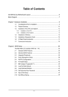
Table of Contents GA-8I915G Duo Motherboard Layout 6 Block Diagram ...7 Chapter 1 Hardware Installation 9 1-1 Considerations Prior Introduction 18 Chapter 2 BIOS Setup 29 The Main Menu (For example: BIOS Ver. : F4 30 2-1 Standard CMOS Features 32 2-2 Advanced BIOS Features 34 2-3 Integrated - Gigabyte GA-8I915G Duo | Manual - Page 5
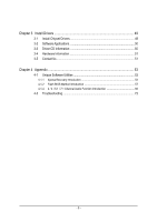
3-3 Driver CD Information 50 3-4 Hardware Information 51 3-5 Contact Us ...51 Chapter 4 Appendix 53 4-1 Unique Software Utilities 53 4-1-1 Xpress Recovery Introduction 54 4-1-2 Flash BIOS Method Introduction 57 4-1-4 2 / 4 / 5.1 / 7.1 Channel Audio Function Introduction 66 4-2 Troubleshooting - Gigabyte GA-8I915G Duo | Manual - Page 6
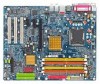
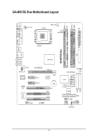
GA-8I915G Duo Motherboard Layout DDRII_2 DDRII_1 DDR1 DDR2 PWR_FAN KB_MS ATX_12V LGA775 ATX SPDIF_O SPDIF_I CPU_FAN VGA LPT IDE1 GA-8I915G Duo USB LAN2 USB AUDIO1 AUDIO2 CD_IN AZALIA_FP Broadcom 5751/5789 CODEC NB_FAN PCIE_1 PCIE_2 IT8712 COMA IR Intel 915G PCIE_16 BIOS - Gigabyte GA-8I915G Duo | Manual - Page 7
Diagram PCI-ECLK (100MHz) VGA LGA775 CPUCLK+/-(200/133MHz) Processor DIMM Dual Channel Memory MCHCLK (133/200MHz) 66MHz 33MHz 14.318MHz 48MHz BIOS 4 Serial ATA ATA33/66/100 IDE1 Channels Floppy IT 8712 LPT Port CODEC motherboard, you must install an 800MHz FSB processor and overclock in - Gigabyte GA-8I915G Duo | Manual - Page 8
- 8 - - Gigabyte GA-8I915G Duo | Manual - Page 9
instructions below: 1. Please turn off the computer and unplug its power cord. 2. When handling the motherboard , avoid touching any metal leads or connectors. 3. It is best to wear an electrostatic discharge (ESD) cuff when handling electronic components (CPU, RAM motherboard problem manual - Gigabyte GA-8I915G Duo | Manual - Page 10
Onboard SATA Peripherals Onboard VGA Onboard LAN Š Supports the latest Intel® Pentium® 4 LGA775 CPU Š Supports 800/533MHz FSB module on the motherboard, you must install an 800MHz FSB processor and overclock in BIOS. (Note 3) Only support ATAPI mode for HDD. GA-8I915G Duo Motherboard - 10 - - Gigabyte GA-8I915G Duo | Manual - Page 11
On-Board IDE RAID (IDE2, IDE3) I/O Control Hardware Monitor BIOS Additional Features Overclocking Form Factor Š C-Media 9880 CODEC (UAJ) Š Supports Jack Sensing function Š Supports 2 / 4 / 5.1 / 7.1 channel audio Š Supports Line In ; Line Out ; MIC ; Back Surround Speaker Out ; Center/Subwoofer - Gigabyte GA-8I915G Duo | Manual - Page 12
the proper specifications, please do so according to your hardware specifications including the An Intel® Chipset that supports HT Technology - BIOS: A BIOS that supports HT Technology and has it might cause damage to the CPU during installation.) GA-8I915G Duo Motherboard - 12 - Fig. 4 Once the - Gigabyte GA-8I915G Duo | Manual - Page 13
make sure the Male and Female push pin are joined closely. (for detailed installation instructions, please refer to the heatsink installation section of the user manual) Fig. 5 Please check the back of motherboard after installing. If the push pin is inserted as the picture, the installation is - Gigabyte GA-8I915G Duo | Manual - Page 14
the module, please switch the direction. The motherboard supports DDR II & DDR memory modules, whereby BIOS will automatically detect memory capacity and specifications. Memory modules are designed so that they can steps when you wish to remove the DIMM module. GA-8I915G Duo Motherboard - 14 - - Gigabyte GA-8I915G Duo | Manual - Page 15
GA-8I915G Duo supports the Dual Channel Technology. After operating the Dual Channel Technology, the bandwidth of Memory Bus will add double up to 6.4GB/s(DDR) ; 8.5GB(DDRII) GA-8I915G Duo explanations due to the limitation of Intel chipset specifications. 1. One DDR/DDR II memory module is - Gigabyte GA-8I915G Duo | Manual - Page 16
card's instruction document BIOS utility of expansion card from BIOS. 8. Install related driver VGA card. Please align the VGA card to the onboard PCI Express x 16 slot and press firmly down on the slot .Make sure your VGA card is locked by the small white-drawable bar. GA-8I915G Duo Motherboard - Gigabyte GA-8I915G Duo | Manual - Page 17
providing digital audio to external speakers VGA Port Monitor can be connected to VGA support USB controller, please contact OS vendor for possible patch or driver upgrade. For more information please contact your OS or device(s) vendors. LAN Port The provided Internet connection is Gigabit Ethernet - Gigabyte GA-8I915G Duo | Manual - Page 18
Speaker Out Connect the surround channels to this connector. You can use audio software to configure 2-/4-/5.1-/7.1-channel audio functioning. 1-7 Connectors Introduction 1 53 2 8 14 13 18 6 15) F_USB1 / F_USB2 16) COM A 17) IR 18) CLR_CMOS 19) BAT GA-8I915G Duo Motherboard - 18 - - Gigabyte GA-8I915G Duo | Manual - Page 19
enough stable power to all the components on the motherboard. Before connecting the power connector, please make sure 24-pin ATX power supply, please remove the small cover on the power connector on the motherboard before plugging in the power cord ; Otherwise, please do not remove it. 13 24 - Gigabyte GA-8I915G Duo | Manual - Page 20
installed wrong direction, the chip fan will not work. Sometimes will damage the chip fan. (Usually black cable is GND) Pin No. Definition 1 1 +12V 2 GND GA-8I915G Duo Motherboard - 20 - - Gigabyte GA-8I915G Duo | Manual - Page 21
other end of the cable connects to the FDD drive. The types of FDD drives supported are: 360KB, 720KB, 1.2MB, 1.44MB and 2.88MB. Please connect the red the other as Slave (for information on settings, please refer to the instructions located on the IDE device). To ensure that an IDE CD-ROM drive - Gigabyte GA-8I915G Duo | Manual - Page 22
ATA Connector) Serial ATA can provide 150MB/s transfer rate. Please refer to the BIOS setting for the Serial ATA and install the proper driver in order to work properly. Pin No. Definition 1 GND 7 1 2 mode. Pin No. Definition 1 1 MPD+ 2 MPD- 3 MPD- GA-8I915G Duo Motherboard - 22 - - Gigabyte GA-8I915G Duo | Manual - Page 23
English 12) F_PANEL (Front Panel Jumper) Please connect the power LED, PC peaker, reset switch and power switch etc of your chassis front panel to the F_PANEL connector according to the pin assignment below. Message LED/ Power/ Sleep LED Speaker Connector Power Switch MSG+ MSG- PW+ PWSPEAK+ - Gigabyte GA-8I915G Duo | Manual - Page 24
setting for this connector. To enable AC'97 Audio, from BIOS settings, set Front Panel Type under Integrated Peripherals to AC97. 14) CD_IN (CD IN) Connect CD-ROM or DVD-ROM audio out to the connector. Pin No. Definition 1 1 CD-L 2 GND 3 GND 4 CD-R GA-8I915G Duo Motherboard - 24 - - Gigabyte GA-8I915G Duo | Manual - Page 25
to work or even damage it. For optional front USB cable, please contact your local dealer. The "USB Device Wake up From S3" is only supported by rear USB ports. 2 10 1 9 Pin No. 1 2 3 4 5 6 7 8 9 10 Definition Power Power USB DXUSB DyUSB DX+ USB Dy+ GND GND No Pin NC 16) COMA (Serial - Gigabyte GA-8I915G Duo | Manual - Page 26
this jumper. To clear CMOS, temporarily short 1-2 pin. Default doesn't include the "Shunter" to prevent from improper use this jumper. 1 Open: Normal 1 Short: Clear CMOS GA-8I915G Duo Motherboard - 26 - - Gigabyte GA-8I915G Duo | Manual - Page 27
is incorrectly replaced. Replace only with the same or equivalent type recommended by the manufacturer. Dispose of used batteries according to the manufacturer's instructions. If you want to erase CMOS... 1.Turn OFF the computer and unplug the power cord. 2.Remove the battery, wait for 30 second - Gigabyte GA-8I915G Duo | Manual - Page 28
English GA-8I915G Duo Motherboard - 28 - - Gigabyte GA-8I915G Duo | Manual - Page 29
a new BIOS, either Gigabyte's Q-Flash or @BIOS utility can be used. Q-Flash allows the user to quickly and easily update or backup BIOS without entering the operating system. @BIOS is a Windows-based utility that does not require users to boot to DOS before upgrading BIOS but directly download and - Gigabyte GA-8I915G Duo | Manual - Page 30
please press "Ctrl+F1" to search the advanced option hidden. Please Load Optimized Defaults in the BIOS when somehow the system works not stable as usual. This action makes the system reset to the default which the system would be in best performance configuration. GA-8I915G Duo Motherboard - 30 - - Gigabyte GA-8I915G Duo | Manual - Page 31
system. „ Save & Exit Setup Save CMOS value settings to CMOS and exit setup. „ Exit Without Saving Abandon all CMOS value changes and exit setup. - 31 - BIOS Setup - Gigabyte GA-8I915G Duo | Manual - Page 32
. Week Month The week, from Sun to Sat, determined by the BIOS and is display only The month, Jan. Through Dec. Day The day, detection step and allow for faster system start up. Manual User can manually input the correct settings Access Mode Use this to GA-8I915G Duo Motherboard - 32 - - Gigabyte GA-8I915G Duo | Manual - Page 33
88M, 3.5" 3.5 inch double-sided drive; 2.88M byte capacity. Floppy 3 Mode Support (for Japan Area) Disabled Normal Floppy Drive. (Default value) Drive A Drive on the motherboard, or 640K for systems with 640K or more memory installed on the motherboard. Extended Memory The BIOS determines how - Gigabyte GA-8I915G Duo | Manual - Page 34
by USB-CDROM. USB-HDD Select your boot device priority by USB-HDD. LAN Select your boot device priority by LAN. Disabled Select your boot device priority by Disabled. (Note) This item will show up when you install a processor which supports this function. GA-8I915G Duo Motherboard - 34 - - Gigabyte GA-8I915G Duo | Manual - Page 35
system with multi processors mode supported. (Default value) Disables CPU Hyper Threading. Limit CPUID Max. to 3 Enabled Disabled Limit CPUID Maximum value to 3 when use older OS like NT4. Disables CPUID Limit for windows supports this function. - 35 - BIOS Setup - Gigabyte GA-8I915G Duo | Manual - Page 36
Set to USB Controller USB 2.0 Controller USB Keyboard Support USB Mouse Support Azalia Codec Front Panel Type Onboard H/W RAID Onboard H/W LAN Onboard LAN Boot ROM Onboard Serial Port 1 Onboard IrDA Port value) Disabled Disable onboard 1st channel IDE port. GA-8I915G Duo Motherboard - 36 - - Gigabyte GA-8I915G Duo | Manual - Page 37
. Disabled Disable USB Keyboard Support. (Default value) USB Mouse Support Enabled Enable USB Mouse Support. Disabled Disable USB Mouse Support. (Default value) Azalia Codec Auto Disabled Auto detect Azalia audio function. (Default value) Disable Azalia audio function. Front Panel Type - Gigabyte GA-8I915G Duo | Manual - Page 38
invoke the boot ROM of the onboard LAN chip. Enabled Disabled Enable this function. Disable this function. (Default value) Onboard Serial Port 1 Auto BIOS will automatically setup the port 1 address. Use DMA to 3. (Default value) 1 Set ECP Mode Use DMA to 1. GA-8I915G Duo Motherboard - 38 - - Gigabyte GA-8I915G Duo | Manual - Page 39
ACPI suspend type to S1/POS(Power On Suspend). (Default value) Set ACPI suspend type to S3/STR(Suspend To RAM). Soft-off by PWR-BTTN Instant-off Press power button then Power off instantly. (Default value) Delay 4 Sec. click on PS/2 mouse left button to power on the system. - 39 - BIOS Setup - Gigabyte GA-8I915G Duo | Manual - Page 40
system always in "On" state. Memory When AC-power back to the system, the system will return to the Last state before AC-power off. GA-8I915G Duo Motherboard - 40 - - Gigabyte GA-8I915G Duo | Manual - Page 41
IRQ 3,4,5,7,9,10,11,12,14,15 to PCI 2. Auto assign IRQ to PCI 3. (Default value) Set IRQ 3,4,5,7,9,10,11,12,14,15 to PCI 3. - 41 - BIOS Setup - Gigabyte GA-8I915G Duo | Manual - Page 42
is more than 41 degree and less than 65 degree. c. When the CPU temperature is lower than 40 degrees Celsius, CPU fan will be disable. GA-8I915G Duo Motherboard - 42 - - Gigabyte GA-8I915G Duo | Manual - Page 43
Smart FAN Control is enabled. Auto BIOS autodetects the type of CPU fan not designed following Intel 4-Wire fans PWM control specifications. With such CPU fans, selecting PWM will Graphics Booster Select the options can enhance the VGA graphics card bandwidth to get higher performance. Auto - Gigabyte GA-8I915G Duo | Manual - Page 44
to +0.1V. +0.2V Set DIMM OverVoltage Control to +0.2V. +0.3V Set DIMM OverVoltage Control to +0.3V. (Note) To use a DDRII 600 memory module on the motherboard, you must install an 800MHz FSB processor and set Memory Frequency For to 3.00. GA-8I915G Duo Motherboard - 44 - - Gigabyte GA-8I915G Duo | Manual - Page 45
to +0.2V. +0.3V Set PCI-E OverVoltage Control to +0.3V. CPU Voltage Control Supports adjustable CPU Vcore from 0.8375V to 1.6000V. (Default value: Normal) Warning: Standard CMOS Features Load Fail-Safe Defaults ` Advanced BIOS Features Load Optimized Defaults ` Integrated Peripherals Set - Gigabyte GA-8I915G Duo | Manual - Page 46
for BIOS and BIOS Features Menu, you will be prompted for the password every time the system is rebooted or any time you try to enter Setup Menu. If you select "Setup" at "Password Check" in Advance BIOS Features Menu, you will be prompted only when you try to enter Setup. GA-8I915G Duo Motherboard - Gigabyte GA-8I915G Duo | Manual - Page 47
Exit Setup CMOS Setup Utility-Copyright (C) 1984-2004 Award Software ` Standard CMOS Features Load Fail-Safe Defaults ` Advanced BIOS Features Load Optimized Defaults ` Integrated Peripherals Set Supervisor Password ` Power Management Setup Set User Password ` PnP/PCI Configurations Save - Gigabyte GA-8I915G Duo | Manual - Page 48
English GA-8I915G Duo Motherboard - 48 - - Gigabyte GA-8I915G Duo | Manual - Page 49
will continue to install other drivers. System will reboot automatically after install the drivers, afterward you can install others application. For USB2.0 driver support under Windows XP operating system, please use Windows Service Pack. After install Windows Service Pack, it will show a question - Gigabyte GA-8I915G Duo | Manual - Page 50
Applications This page displays all the tools that Gigabyte developed and some free software, you can choose anyone you want and press "install" to install them. 3-3 Driver CD Information This page lists the contents of software and drivers in this CD-title. GA-8I915G Duo Motherboard - 50 - - Gigabyte GA-8I915G Duo | Manual - Page 51
English 3-4 Hardware Information This page lists all device you have for this motherboard. 3-5 Contact Us Please see the last page for details. - 51 - Install Drivers - Gigabyte GA-8I915G Duo | Manual - Page 52
English GA-8I915G Duo Motherboard - 52 - - Gigabyte GA-8I915G Duo | Manual - Page 53
factory defaults to provide a more user-friendly and reliable platform for users. Download Center Download Center allows users to quickly download and update their BIOS as well as the latest drivers for their system. Download Center automatically runs a system check of the user PC and provides the - Gigabyte GA-8I915G Duo | Manual - Page 54
on. . . Verifying DMI Pool Data Boot from CD: Boot from CD: Xpress Recovery V1.0 (C) Copy Right 2003. GIGABYTE Technology CO. , Ltd. 1. Execute Backup Utility 2. Execute Restore Utility 3. Remove Backup Image 4. Set Password 5. Exit and Restart Build 2011 GA-8I915G Duo Motherboard - 54 - - Gigabyte GA-8I915G Duo | Manual - Page 55
BIOS for 8IPE1000MT F1 Check System Health OK . . . Press DEL to enter SETUP / Q-Flash, F9 For Xpress Recovery 08/16/2002-I845GE-6A69YG01C-00 F9 For Xpress Recovery Xpress Recovery V1.0 (C) Copy Right 2003. GIGABYTE and all required driver and software installations are complete. - 55 - Appendix - Gigabyte GA-8I915G Duo | Manual - Page 56
your system and back up data as a backup image in your hard drive. Not all systems support access to Xpress Recovery by pressing the F9 key during computer power on. If this is the case password requirement. 5. Exit and Restart: Exit and restart your computer. GA-8I915G Duo Motherboard - 56 - - Gigabyte GA-8I915G Duo | Manual - Page 57
of Gigabyte motherboards are equipped with dual BIOS. In the BIOS menu of the motherboards supporting Q-Flash and Dual BIOS, the Q-Flash utility and Dual BIOS utility are combined in the same screen. This section only deals with how to use Q-Flash utility. In the following sections, we take GA-8KNXP - Gigabyte GA-8I915G Duo | Manual - Page 58
Enter key on your keyboard to enable execution of the task. Action bar: Contains the names of four actions needed to operate the Q-Flash/Dual BIOS utility. Pressing the buttons mentioned on your keyboards to perform these actions. GA-8I915G Duo Motherboard - 58 - - Gigabyte GA-8I915G Duo | Manual - Page 59
flash and press Enter. In this example, we only download one BIOS file to the floppy disk so only one BIOS file, 8KNXPU.Fba, is listed. Please confirm again you have the correct BIOS file for your motherboard. Dual BIOS Utility Boot From Main Bios Main ROM Type/Size SST 49LF004A Backup ROM Type - Gigabyte GA-8I915G Duo | Manual - Page 60
Primary Master : FUJITSU MPE3170AT ED-03-08 Primary Slave : None Secondary Master : CREATIVEDVD-RM DVD1242E BC101 Secondary Slave : None Press DEL to enter SETUP / Dual BIOS / Q-Flash / F9 For Xpress Recovery 09/23/2003-i875P-6A79BG03C-00 GA-8I915G Duo Motherboard - 60 - - Gigabyte GA-8I915G Duo | Manual - Page 61
Disk Type... Press Y on your keyboard to save and exit. Part Two: Updating BIOS with Q-FlashTM Utility on Single-BIOS Motherboards. This part guides users of single-BIOS motherboards how to update BIOS using the Q-FlashTM utility. CMOS Setup Utility-Copyright (C) 1984-2004 Award Software Standard - Gigabyte GA-8I915G Duo | Manual - Page 62
SyCs:tRemeset F10:Power Off Do not trun off power or reset your system at this stage!! After BIOS file is read, you'll see a confirmation dialog box asking you "Are you sure to update BIOS?" Please do not take out the floppy disk when it begins flashing BIOS. GA-8I915G Duo Motherboard - 62 - - Gigabyte GA-8I915G Duo | Manual - Page 63
:Power Off Do not trun off power or reset your system at this stage!! 4. Press any keys to return to the Q-Flash menu when the BIOS updating procedure is completed. Q-Flash Utility V1.30 Flash Type/Size SST 49LF002A 256K Enter : Run Keep DMI Data Enable !! CopUypdBaItOe SBIcOomS fprloemtedFl - Gigabyte GA-8I915G Duo | Manual - Page 64
b. Click "Update New BIOS" c. Please select "All Files" in dialog box while opening the old file. d. Please search for BIOS unzip file, downloading from internet or any other methods (such as: 8I915G Duo.F1). e. Complete update process following the instruction. GA-8I915G Duo Motherboard - 64 - - Gigabyte GA-8I915G Duo | Manual - Page 65
In method II, be sure that motherboard's model name in BIOS unzip file are the same as your motherboard's. Otherwise, your system won't boot. III. In method I, if the BIOS file you need cannot be found in @BIOSTM server, please go onto Gigabyte's web site for downloading and updating it according to - Gigabyte GA-8I915G Duo | Manual - Page 66
audio driver, you'll find an icon in the system area. Double click the icon to select the function. If the icon can not be found, go to the control panel from the system menu and double click the C-Media CPL icon. Open "CMI Audio output devices are configured.) GA-8I915G Duo Motherboard - 66 - - Gigabyte GA-8I915G Duo | Manual - Page 67
: We recommend that you use speakers with amplifier to acquire the best sound effect if the stereo output is applied. STEP 1: Connect the stereo speakers or earphone to "Line Out". Line Out STEP 2: After installation of the audio driver, you'll find an icon in the system area. Double click the - Gigabyte GA-8I915G Duo | Manual - Page 68
current audio mode is display in "Audio System Status". "Smart Jack" would auto-detect the speaker type you connect and gives you the functions to manually modify speaker the settings. The function to manually modify speaker setting. The function to adjust speaker volume. GA-8I915G Duo Motherboard - Gigabyte GA-8I915G Duo | Manual - Page 69
Speaker Out". STEP 2: After installation of the audio driver, you find an icon in the system area. audio mode is display in "Audio System Status". "Smart Jack" would auto-detect the speaker type you connect and gives you the functions to manually modify speaker the settings. The function to manually - Gigabyte GA-8I915G Duo | Manual - Page 70
current audio mode is display in "Audio System Status". "Smart Jack" would auto-detect the speaker type you connect and gives you the functions to manually modify speaker the settings. The function to manually modify speaker setting. The function to adjust speaker volume. GA-8I915G Duo Motherboard - Gigabyte GA-8I915G Duo | Manual - Page 71
of Equalizer here. Device Setting Check "Enable Multiple Streaming" and restart the system to enable support for multiple audio output function. Defaults: The defaults for both "Sound Playback "and"Sound Recording " are "C-Media Azalia Rear Panel". After you check the "Enable Multiple Steaming" item - Gigabyte GA-8I915G Duo | Manual - Page 72
later. Question 6: How do I disable onboard VGA card in order to add an external VGA card? Answer: Gigabyte motherboards will auto-detect the external VGA card after it is plugged in, so you don't need to change any setting manually to disable the onboard VGA. GA-8I915G Duo Motherboard - 72 - - Gigabyte GA-8I915G Duo | Manual - Page 73
Answer: Please refer to the user manual and check whether you have connected any cable that is not provided with the motherboard package to the USB Over Current computer problems. However, they are only for reference purposes. The situations might differ from case to case. AMI BIOS Beep Codes - Gigabyte GA-8I915G Duo | Manual - Page 74
English GA-8I915G Duo Motherboard - 74 - - Gigabyte GA-8I915G Duo | Manual - Page 75
- 75 - Appendix English - Gigabyte GA-8I915G Duo | Manual - Page 76
English GA-8I915G Duo Motherboard - 76 - - Gigabyte GA-8I915G Duo | Manual - Page 77
- 77 - Appendix English - Gigabyte GA-8I915G Duo | Manual - Page 78
English GA-8I915G Duo Motherboard - 78 - - Gigabyte GA-8I915G Duo | Manual - Page 79
Milton Keynes, MK1 1DR, UK, England TEL: +44-1908-362700 FAX: +44-1908-362709 Tech. Support : http://uk.giga-byte.com/TechSupport/ServiceCenter.htm Non-Tech. Support(Sales/Marketing) : http://ggts.gigabyte.com.tw/nontech.asp WEB address : http://uk.giga-byte.com The Netherlands GIGA-BYTE TECHNOLOGY - Gigabyte GA-8I915G Duo | Manual - Page 80
://www.gigabyte.ru Poland Representative Office Of Giga-Byte Technology Co., Ltd. POLAND Tech. Support : http://tw.giga-byte.com/TechSupport/ServiceCenter.htm Non-Tech. Support(Sales/Marketing) : http://ggts.gigabyte.com.tw/nontech.asp WEB address : http://www.gigabyte.pl GA-8I915G Duo Motherboard
-
 1
1 -
 2
2 -
 3
3 -
 4
4 -
 5
5 -
 6
6 -
 7
7 -
8
-
9
-
10
-
11
-
12
-
13
-
14
-
15
-
16
-
17
-
18
-
19
-
20
-
21
-
22
-
23
-
24
-
25
-
26
-
27
-
28
-
29
-
30
-
31
-
32
-
33
-
34
-
35
-
36
-
37
-
38
-
39
-
40
-
41
-
42
-
43
-
44
-
45
-
46
-
47
-
48
-
49
-
50
-
51
-
52
-
53
-
54
-
55
-
56
-
57
-
58
-
59
-
60
-
61
-
62
-
63
-
64
-
65
-
66
-
67
-
68
-
69
-
70
-
71
-
72
-
73
-
74
-
75
-
76
-
77
-
78
-
79
-
80
 |
 |

GA-8I915G Duo
Intel
®
Pentium
®
4 LGA775 Processor Motherboard
User's Manual
Rev. 1303
12ME-8I915GDUO-1303