Gigabyte GA-8I915GV-M Manual
Gigabyte GA-8I915GV-M Manual
 |
View all Gigabyte GA-8I915GV-M manuals
Add to My Manuals
Save this manual to your list of manuals |
Gigabyte GA-8I915GV-M manual content summary:
- Gigabyte GA-8I915GV-M | Manual - Page 1
GA-8I915GV-MF/ GA-8I915GVM Intel® Pentium® 4 LGA775 Processor Motherboard User's Manual Rev. 1202 12ME-I915GVMF-1202 * The WEEE marking on the product indicates this product must not be disposed of with user's other household waste and - Gigabyte GA-8I915GV-M | Manual - Page 2
Motherboard GA-8I915GV-MF/GA-8I915GVM Nov. 24, 2004 Motherboard GA-8I915GV-MF/ GA-8I915GVM Nov. 24, 2004 - Gigabyte GA-8I915GV-M | Manual - Page 3
Copyright © 2004 GIGA-BYTE TECHNOLOGY CO., LTD. All rights reserved. The trademarks mentioned in the manual are legally registered to their respective companies. Notice The written content provided with this product is the property of Gigabyte. No part of this manual may be reproduced, copied, - Gigabyte GA-8I915GV-M | Manual - Page 4
Table of Content GA-8I915GV-MF/GA-8I915GVM Motherboard Layout 6 Block Diagram ...7 Chapter 1 Hardware Installation 9 1-1 Considerations Prior to 18 Chapter 2 BIOS Setup 29 The Main Menu (For example: BIOS Ver. : E2 30 2-1 Standard CMOS Features 32 2-2 Advanced BIOS Features 34 2-3 - Gigabyte GA-8I915GV-M | Manual - Page 5
49 3-5 Contact Us ...49 Chapter 4 Appendix 51 4-1 Unique Software Utilities 51 4-1-1 EasyTune 5 Introduction 52 4-1-2 Xpress Recovery Introduction 53 4-1-3 Flash BIOS Method Introduction 56 4-1-4 2- / 4- / 6- / 8- Channel Audio Function Introduction 65 4-2 Troubleshooting 69 - 5 - - Gigabyte GA-8I915GV-M | Manual - Page 6
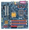
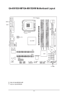
GA-8I915GV-MF/GA-8I915GVM Motherboard Layout IT8712 KB_MS SPDIF_O SPDIF_I CPU_FAN SYS_FAN IR ATX GA-8I915GV-MF/GA-8I915GVM DDR1 DDR2 VGA LPT R_USB ATX_12V LGA775 USB LAN AZALIA_FP AUDIO1 AUDIO2 RTL8110S RTL8100C Intel 915GV PCI1 DDR3 DDR4 IDE FDD BAT CLR_CMOS CD_IN CODEC PCIE_1 - Gigabyte GA-8I915GV-M | Manual - Page 7
TSB43AB23 RJ45 3 IEEE1394 2 PCI Host Interface DDR400/333MHz DIMM Intel 915GV GMCH Dual Channel Memory GMCHCLK (200/133MHz) 66MHz 33MHz 14.318MHz 48MHz BIOS 4 Serial ATA Intel ATA33/66/100 ICH6 -In SPDIF In SPDIF Out PCICLK (33MHz) Only for GA-8I915GV-MF. Only for GA-8I915GVM. - 7 - - Gigabyte GA-8I915GV-M | Manual - Page 8
- 8 - - Gigabyte GA-8I915GV-M | Manual - Page 9
instructions below: 1. Please turn off the computer and unplug its power cord. 2. When handling the motherboard motherboard. Installation Notices 1. Prior to installation, please do not remove the stickers on the motherboard the motherboard or or have a problem related to the the user manual. 3. Damage - Gigabyte GA-8I915GV-M | Manual - Page 10
LAN Onboard Audio Š Supports the latest Intel® Pentium® 4 LGA775 CPU Š Supports Š 4 Serial ATA connections Š 1 parallel port supporting Normal/EPP/ECP mode Š 1 VGA port, onboard COMA/COMB connection Š 8 USB 2.0/1.1 GA-8I915GV-MF. Only for GA-8I915GVM. GA-8I915GV-MF/GA-8I915GVM Motherboard - 10 - - Gigabyte GA-8I915GV-M | Manual - Page 11
/ System fan failure warning Š CPU smart fan control BIOS Š Use of licensed AWARD BIOS Š Supports Q-Flash Additional Features Š Supports @BIOS Š Supports EasyTune 5 (only supports Hardware Monitor function) Overclocking Š Over Clock via BIOS (DDR) Form Factor Š Micro ATX form factor; 24 - Gigabyte GA-8I915GV-M | Manual - Page 12
HT Technology - Chipset: An Intel® Chipset that supports HT Technology - BIOS: A BIOS that supports HT Technology and has it enabled - OS: bending motions that might cause damage to the CPU during installation.) GA-8I915GV-MF/GA-8I915GVM Motherboard - 12 - Fig. 4 Once the CPU is properly inserted, - Gigabyte GA-8I915GV-M | Manual - Page 13
make sure the Male and Female push pin are joined closely. (for detailed installation instructions, please refer to the heatsink installation section of the user manual) Fig. 5 Please check the back of motherboard after installing. If the push pin is inserted as the picture, the installation is - Gigabyte GA-8I915GV-M | Manual - Page 14
are unable to insert the module, please switch the direction. The motherboard supports DDR memory modules, whereby BIOS will automatically detect memory capacity and specifications. Memory modules are designed so when you wish to remove the DIMM module. GA-8I915GV-MF/GA-8I915GVM Motherboard - 14 - - Gigabyte GA-8I915GV-M | Manual - Page 15
English GA-8I915GV-MF/GA-8I915GVM supports the Dual Channel Technology. After operating the Dual Channel Technology, the bandwidth of Memory Bus will double. GA-8I915GV-MF/GA-8I915GVM includes 4 DIMM sockets, and each Channel has two DIMM sockets as following: Channel A : DDR 1, DDR 2 Channel B : - Gigabyte GA-8I915GV-M | Manual - Page 16
steps outlined below: 1. Read the related expansion card's instruction document before install the expansion card into the computer. 2. BIOS utility of expansion card from BIOS. 8. Install related driver from the operating system. Installing a PCI expansion card: GA-8I915GV-MF/GA-8I915GVM Motherboard - Gigabyte GA-8I915GV-M | Manual - Page 17
digital audio to external supports USB controller. If your OS does not support USB controller, please contact OS vendor for possible patch or driver upgrade. For more information please contact your OS or device(s) vendors. LAN GA-8I915GV-MF. Only for GA-8I915GVM. - 17 - Hardware Installation - Gigabyte GA-8I915GV-M | Manual - Page 18
Out Connect the side surround speakers to this connector. You can use audio software to configure 2-/4-/6-/8-channel audio functioning. 1-7 Connectors Introduction 3 2 14 4 1 5 10 6 14) IR 15) COMA / COMB 16) CLR_CMOS 17) BAT Only for GA-8I915GV-MF. GA-8I915GV-MF/GA-8I915GVM Motherboard - 18 - - Gigabyte GA-8I915GV-M | Manual - Page 19
a system that is unable to start. If you use a 24-pin ATX power supply, please remove the small cover on the power connector on the motherboard before plugging in the power cord ; Otherwise, please do not remove it. 42 31 Pin No. 1 2 3 4 Definition GND GND +12V +12V Pin No. Definition 13 - Gigabyte GA-8I915GV-M | Manual - Page 20
is used to connect the FDD cable while the other end of the cable connects to the FDD drive. The types of FDD drives supported are: 360KB, 720KB, 1.2MB, 1.44MB and 2.88MB. Please connect the red power connector wire to the pin1 position. 34 33 2 1 GA-8I915GV-MF/GA-8I915GVM Motherboard - 20 - - Gigabyte GA-8I915GV-M | Manual - Page 21
other as Slave (for information on settings, please refer to the instructions located on the IDE device). 40 39 2 1 7) SATA0/SATA1 can provide 150MB/s transfer rate. Please refer to the BIOS setting for the Serial ATA and install the proper driver in order to work properly. Pin No. Definition - Gigabyte GA-8I915GV-M | Manual - Page 22
2- Pin 3: NC Pin 4: Data(-) Open: Normal Operation Close: Reset Hardware System Open: Normal Operation Close: Power On/Off Pin 1: LED anode(+) Pin 2: LED cathode(-) NC GA-8I915GV-MF/GA-8I915GVM Motherboard - 22 - - Gigabyte GA-8I915GV-M | Manual - Page 23
Audio Panel Connector) This connector is supported to connect HD(High Definition) Audio and AC'97 Audio. Check the pin assignment carefully while you connect the audio Out (L) 10 N/A HD Audio is the default setting for this connector. To enable AC'97 Audio, from BIOS settings, set Front Panel Type - Gigabyte GA-8I915GV-M | Manual - Page 24
CD_IN (CD IN) Connect CD-ROM or DVD-ROM audio out to the connector. 1 Pin No. Definition 1 supported by rear USB ports. Pin No. Definition 1 Power 2 Power 9 1 3 USB DX- 4 USB Dy- 10 2 5 USB DX+ 6 USB Dy+ 7 GND 8 GND 9 No Pin 10 NC GA-8I915GV-MF/GA-8I915GVM Motherboard - Gigabyte GA-8I915GV-M | Manual - Page 25
connect the IR. Please contact your nearest dealer for optional IR device. Pin No. Definition 1 VCC 2 No Pin 3 IR RX 1 4 GND 5 IR TX Only for GA-8I915GV-MF. - 25 - Hardware Installation - Gigabyte GA-8I915GV-M | Manual - Page 26
this jumper. To clear CMOS, temporarily short 1-2 pin. Default doesn't include the "Shunter" to prevent from improper use this jumper. 1 Open: Normal 1 Short :Clear CMOS GA-8I915GV-MF/GA-8I915GVM Motherboard - 26 - - Gigabyte GA-8I915GV-M | Manual - Page 27
is incorrectly replaced. Replace only with the same or equivalent type recommended by the manufacturer. Dispose of used batteries according to the manufacturer's instructions. If you want to erase CMOS... 1.Turn OFF the computer and unplug the power cord. 2.Remove the battery, wait for 30 second - Gigabyte GA-8I915GV-M | Manual - Page 28
English GA-8I915GV-MF/GA-8I915GVM Motherboard - 28 - - Gigabyte GA-8I915GV-M | Manual - Page 29
a new BIOS, either Gigabyte's Q-Flash or @BIOS utility can be used. Q-Flash allows the user to quickly and easily update or backup BIOS without entering the operating system. @BIOS is a Windows-based utility that does not require users to boot to DOS before upgrading BIOS but directly download and - Gigabyte GA-8I915GV-M | Manual - Page 30
please press "Ctrl+F1" to search the advanced option hidden. Please Load Optimized Defaults in the BIOS when somehow the system works not stable as usual. This action makes the system reset to the limit access to the system and Setup, or just to Setup. GA-8I915GV-MF/GA-8I915GVM Motherboard - 30 - - Gigabyte GA-8I915GV-M | Manual - Page 31
English „ Set User Password Change, set, or disable password. It allows you to limit access to the system. „ Save & Exit Setup Save CMOS value settings to CMOS and exit setup. „ Exit Without Saving Abandon all CMOS value changes and exit setup. - 31 - BIOS Setup - Gigabyte GA-8I915GV-M | Manual - Page 32
>, . Week The week, from Sun to Sat, determined by the BIOS and is display only Month The month, Jan. Through Dec. Day The step and allow for faster system start up. Manual User can manually input the correct settings Access Mode Use this to GA-8I915GV-MF/GA-8I915GVM Motherboard - 32 - - Gigabyte GA-8I915GV-M | Manual - Page 33
byte capacity 1.44M, 3.5" 2.88M, 3.5" 3.5 inch double-sided drive; 1.44M byte capacity. 3.5 inch double-sided drive; 2.88M byte capacity. Floppy 3 Mode Support on the motherboard, or 640K for systems with 640K or more memory installed on the motherboard. Extended Memory The BIOS determines how - Gigabyte GA-8I915GV-M | Manual - Page 34
1984-2004 Award Software Advanced BIOS Features ` Hard Disk Boot LAN Select your boot device priority by LAN. Disabled Select your boot device priority by Disabled. (Note) This item will show up when you install a processor which supports this function. GA-8I915GV-MF/GA-8I915GVM Motherboard - Gigabyte GA-8I915GV-M | Manual - Page 35
Please note that this feature is only working for operating system with multi processors mode supported. (Default value) Disabled Disables CPU Hyper Threading. Limit CPUID Max. to 3 Enabled ) This item will show up when you install a processor which supports this function. - 35 - BIOS Setup - Gigabyte GA-8I915GV-M | Manual - Page 36
to USB Controller USB 2.0 Controller USB Keyboard Support USB Mouse Support Azalia Codec Front Panel Type Onboard H/W 1394 1 Onboard H/W LAN Onboard LAN Boot ROM Onboard Serial Port 1 Onboard Serial onboard 1st channel IDE port. Only for GA-8I915GV-MF. GA-8I915GV-MF/GA-8I915GVM Motherboard - 36 - - Gigabyte GA-8I915GV-M | Manual - Page 37
. Disabled Disable USB Keyboard Support. (Default value) USB Mouse Support Enabled Enable USB Mouse Support. Disabled Disable USB Mouse Support. (Default value) Azalia Codec Auto Disabled Auto detect Azalia audio function. (Default value) Disable Azalia audio function. Front Panel Type - Gigabyte GA-8I915GV-M | Manual - Page 38
the boot ROM of the onboard LAN chip. Enabled Enable this function. Disabled Disable this function. (Default value) Onboard Serial Port 1 Auto BIOS will automatically setup the port 1 LPT port and address is 3BC/IRQ7. Only for GA-8I915GV-MF. GA-8I915GV-MF/GA-8I915GVM Motherboard - 38 - - Gigabyte GA-8I915GV-M | Manual - Page 39
Wake up. (Default value) Power On by Ring Disabled Disable Power on by Ring function. Enabled Enable Power on by Ring function. (Default value) - 39 - BIOS Setup - Gigabyte GA-8I915GV-M | Manual - Page 40
, the system always in "On" state. When AC-power back to the system, the system will return to the Last state before AC-power off. GA-8I915GV-MF/GA-8I915GVM Motherboard - 40 - - Gigabyte GA-8I915GV-M | Manual - Page 41
IRQ 3,4,5,7,9,10,11,12,14,15 to PCI 1. Auto assign IRQ to PCI 2. (Default value) Set IRQ 3,4,5,7,9,10,11,12,14,15 to PCI 2. - 41 - BIOS Setup - Gigabyte GA-8I915GV-M | Manual - Page 42
temperature is more than 41 degree and less than 65 degree. c. When the CPU temperature is lower than 40 degrees Celsius, CPU fan willbe disable. GA-8I915GV-MF/GA-8I915GVM Motherboard - 42 - - Gigabyte GA-8I915GV-M | Manual - Page 43
FAN Mode This option is available only when CPU Smart FAN Control is enabled. Auto BIOS autodetects the type of CPU fan you installed and sets the optimal CPU Smart FAN control data. (Default value) Memory Frequency (Mhz) The values depend on "Memory Frequency For" item. - 43 - BIOS Setup - Gigabyte GA-8I915GV-M | Manual - Page 44
Standard CMOS Features Load Fail-Safe Defaults ` Advanced BIOS Features Load Optimized Defaults ` Integrated Peripherals Set Supervisor this field loads the factory defaults for BIOS and Chipset Features which the system automatically detects. GA-8I915GV-MF/GA-8I915GVM Motherboard - 44 - - Gigabyte GA-8I915GV-M | Manual - Page 45
/Set/Disable Password Selecting this field loads the factory defaults for BIOS and Chipset Features which the system automatically detects. When you select basic items. If you select "System" at "Password Check" in Advance BIOS Features Menu, you will be prompted for the password every time the - Gigabyte GA-8I915GV-M | Manual - Page 46
2004 Award Software ` Standard CMOS Features Load Fail-Safe Defaults ` Advanced BIOS Features Load Optimized Defaults ` Integrated Peripherals Set Supervisor Password ` Power Management saving to RTC CMOS. Type "N" will return to Setup Utility. GA-8I915GV-MF/GA-8I915GVM Motherboard - 46 - - Gigabyte GA-8I915GV-M | Manual - Page 47
Pictures below are shown in Windows XP. Insert the driver CD-title that came with your motherboard into your CD-ROM drive, the driver CD-title will auto start and show the installation guide. If not, please double click the CD-ROM device icon in "My computer", and execute the Run.exe. 3-1 Install - Gigabyte GA-8I915GV-M | Manual - Page 48
This page displays all the tools that Gigabyte developed and some free software, you can choose anyone you want and press "install" to install them. 3-3 Driver CD Information This page lists the contents of software and drivers in this CD-title. GA-8I915GV-MF/GA-8I915GVM Motherboard - 48 - - Gigabyte GA-8I915GV-M | Manual - Page 49
English 3-4 Hardware Information This page lists all device you have for this motherboard. 3-5 Contact Us Please see the last page for details. - 49 - Install Drivers - Gigabyte GA-8I915GV-M | Manual - Page 50
English GA-8I915GV-MF/GA-8I915GVM Motherboard - 50 - - Gigabyte GA-8I915GV-M | Manual - Page 51
factory defaults to provide a more user-friendly and reliable platform for users. Download Center Download Center allows users to quickly download and update their BIOS as well as the latest drivers for their system. Download Center automatically runs a system check of the user PC and provides the - Gigabyte GA-8I915GV-M | Manual - Page 52
and Advance Mode Display panel of CPU frequency Shows the current functions status Log on to GIGABYTE website Display EasyTuneTM 5 Help file Quit or Minimize EasyTuneTM 5 software (Note) EasyTune 5 functions may vary depending on different motherboards. GA-8I915GV-MF/GA-8I915GVM Motherboard - 52 - - Gigabyte GA-8I915GV-M | Manual - Page 53
be used with an IDE hard disk supporting HPA 5. The first partition must be BIOS menu, select "Advanced BIOS Feature" and set to boot from CD-ROM. Insert the provided driver CD into your CD drive, then save and exit the BIOS V1.0 (C) Copy Right 2003. GIGABYTE Technology CO. , Ltd. 1. Execute - Gigabyte GA-8I915GV-M | Manual - Page 54
as well as drive reading/writing speed will affect backup speed. 3. It is recommended that Xpress Recovery be immediately installed after OS and all required driver and software installations are complete. GA-8I915GV-MF/GA-8I915GVM Motherboard - 54 - - Gigabyte GA-8I915GV-M | Manual - Page 55
Esc to Exit The backup utility will automatically scan your system and back up data as a backup image in your hard drive. Not all systems support access to Xpress Recovery by pressing the F9 key during computer power on. If this is the case, please use the boot from CD-ROM - Gigabyte GA-8I915GV-M | Manual - Page 56
Primary Master : FUJITSU MPE3170AT ED-03-08 Primary Slave : None Secondary Master : CREATIVEDVD-RM DVD1242E BC101 Secondary Slave : None Press DEL to enter SETUP / Dual BIOS / Q-Flash / F9 For Xpress Recovery 08/07/2003-i875P-6A79BG03C-00 GA-8I915GV-MF/GA-8I915GVM Motherboard - 56 - - Gigabyte GA-8I915GV-M | Manual - Page 57
Backup Load Default Settings Save Settings to CMOS Q-Flash Utility Load Main BIOS from Floppy Load Backup BIOS from Floppy Save Main BIOS to Floppy Save Backup BIOS to Floppy Enter : Run :Move ESC:Reset F10:Power Off Dual BIOS utility bar Q-FlashTM utility title bar Action bar Task menu for - Gigabyte GA-8I915GV-M | Manual - Page 58
Main BIOS to Floppy Save Backup BIOS to Floppy Enter : Run :Move ESC:Reset F10:Power Off Do not trun off power or reset your system at this stage!! After BIOS file is read, you'll see a confirmation dialog box asking you "Are you sure to update BIOS?" GA-8I915GV-MF/GA-8I915GVM Motherboard - Gigabyte GA-8I915GV-M | Manual - Page 59
CPopleyasMe apirneRssOaMnyDkaetya tto cBoanctkiunpue Load Default Settings Save Settings to CMOS Q-Flash Utility Load Main BIOS from Floppy Load Backup BIOS from Floppy Save Main BIOS to Floppy Save Backup BIOS to Floppy Enter : Run :Move ESC:Reset F10:Power Off You can repeat Step 1 to - Gigabyte GA-8I915GV-M | Manual - Page 60
and exit. Part Two: Updating BIOS with Q-FlashTM Utility on Single-BIOS Motherboards. This part guides users of single-BIOS motherboards how to update BIOS using the Q-FlashTM utility. CMOS Language F10: Save & Exit Setup Time, Date, Hard Disk Type... GA-8I915GV-MF/GA-8I915GVM Motherboard - 60 - - Gigabyte GA-8I915GV-M | Manual - Page 61
file you want to flash and press Enter. In this example, we only download one BIOS file to the floppy disk so only one BIOS file, 8GE800.F4, is listed. Please confirm again you have the correct BIOS file for your motherboard. Q-Flash Utility V1.30 Flash Type/Size SST 49LF003A 256K 8GE800.F4Keep - Gigabyte GA-8I915GV-M | Manual - Page 62
-I845GE-6A69YG01C-00 6. Press Del to enter BIOS menu after system reboots and "Load BIOS Fail-Safe Defaults". See how to Load BIOS Fail-Safe Defaults, please kindly refer to Step 6 to 7 in Part One. Congratulation!! You have updated BIOS successfully!! GA-8I915GV-MF/GA-8I915GVM Motherboard - 62 - - Gigabyte GA-8I915GV-M | Manual - Page 63
Update" icon b. Click "Update New BIOS" c. Please select "All Files" in dialog box while opening the old file. d. Please search for BIOS unzip file, downloading from internet or any other methods (such as: 8I915GV-MF.E2). e. Complete update process following the instruction. - 63 - Appendix - Gigabyte GA-8I915GV-M | Manual - Page 64
. III. In method I, if the BIOS file you need cannot be found in @BIOSTM server, please go onto Gigabyte's web site for downloading and updating it according to method II. IV. Please note that any interruption during updating will cause system unbooted GA-8I915GV-MF/GA-8I915GVM Motherboard - 64 - - Gigabyte GA-8I915GV-M | Manual - Page 65
option to HD Audio in BIOS, make sure to connect your audio front panel cable(optional for different models) connector to the motherboard before system "Line Out". Line Out STEP 2 : Following installation of the audio driver, you find a Sound Effect icon on the lower right hand taskbar. - Gigabyte GA-8I915GV-M | Manual - Page 66
the audio driver, you find a Sound Effect icon on the lower right hand taskbar. Click the icon to select the function. STEP 3: Click "Speaker Configuration" then click on the left selection bar and select "4CH Speaker" to complete 4 channel audio configuration. GA-8I915GV-MF/GA-8I915GVM Motherboard - Gigabyte GA-8I915GV-M | Manual - Page 67
the rear channels to "Rear Speaker Out", and the Center/Subwoofer channels to "Center/Subwoofer Speaker Out". STEP 2 : Following installation of the audio driver, you find a Sound Effect icon on the lower right hand taskbar. Click the icon to select the function. STEP 3: Click "Speaker Configuration - Gigabyte GA-8I915GV-M | Manual - Page 68
Following installation of the audio driver, you find a audio configuration. Sound Effect Configuration: At the sound effect menu, users can adjust sound option settings as desired. Front Speaker Out Rear Speaker Out Center/Subwoofer Speaker Out Side Speaker Out GA-8I915GV-MF/GA-8I915GVM Motherboard - Gigabyte GA-8I915GV-M | Manual - Page 69
English 4-2 Troubleshooting Below is a collection of general asked questions. To check general asked questions based on a specific motherboard model, please log on to http://tw.giga-byte.com/faq/faq.htm Question 1: I cannot see some options that were included in previous BIOS after updating BIOS. - Gigabyte GA-8I915GV-M | Manual - Page 70
computer problems. However, they are only for reference purposes. The situations might differ from case to case. AMI BIOS Beep Codes Keyboard error 1 long 9 short: BIOS ROM error Continuous long beeps: DRAM error Continuous short beeps: Power error GA-8I915GV-MF/GA-8I915GVM Motherboard - 70 - - Gigabyte GA-8I915GV-M | Manual - Page 71
- 71 - Appendix English - Gigabyte GA-8I915GV-M | Manual - Page 72
English GA-8I915GV-MF/GA-8I915GVM Motherboard - 72 - - Gigabyte GA-8I915GV-M | Manual - Page 73
- 73 - Appendix English - Gigabyte GA-8I915GV-M | Manual - Page 74
English GA-8I915GV-MF/GA-8I915GVM Motherboard - 74 - - Gigabyte GA-8I915GV-M | Manual - Page 75
- 75 - Appendix English - Gigabyte GA-8I915GV-M | Manual - Page 76
English GA-8I915GV-MF/GA-8I915GVM Motherboard - 76 - - Gigabyte GA-8I915GV-M | Manual - Page 77
- 77 - Appendix English - Gigabyte GA-8I915GV-M | Manual - Page 78
English GA-8I915GV-MF/GA-8I915GVM Motherboard - 78 - - Gigabyte GA-8I915GV-M | Manual - Page 79
WEB address : http://www.gigabyte.de Japan NIPPON GIGA-BYTE CORPORATION WEB address : http://www.gigabyte.co.jp Singapore GIGA-BYTE SINGAPORE PTE. LTD. Tech. Support : http://tw.giga-byte.com/TechSupport/ServiceCenter.htm Non-Tech. Support(Sales/Marketing) : http://ggts.gigabyte.com.tw/nontech.asp - Gigabyte GA-8I915GV-M | Manual - Page 80
Poland Representative Office Of Giga-Byte Technology Co., Ltd. POLAND Tech. Support : http://tw.giga-byte.com/TechSupport/ServiceCenter.htm Non-Tech. Support(Sales/Marketing) : http://ggts.gigabyte.com.tw/nontech.asp WEB address : http://www.gigabyte.pl GA-8I915GV-MF/GA-8I915GVM Motherboard - 80 -
-
 1
1 -
 2
2 -
 3
3 -
 4
4 -
 5
5 -
 6
6 -
 7
7 -
8
-
9
-
10
-
11
-
12
-
13
-
14
-
15
-
16
-
17
-
18
-
19
-
20
-
21
-
22
-
23
-
24
-
25
-
26
-
27
-
28
-
29
-
30
-
31
-
32
-
33
-
34
-
35
-
36
-
37
-
38
-
39
-
40
-
41
-
42
-
43
-
44
-
45
-
46
-
47
-
48
-
49
-
50
-
51
-
52
-
53
-
54
-
55
-
56
-
57
-
58
-
59
-
60
-
61
-
62
-
63
-
64
-
65
-
66
-
67
-
68
-
69
-
70
-
71
-
72
-
73
-
74
-
75
-
76
-
77
-
78
-
79
-
80
 |
 |

GA-8I915GV-MF/
GA-8I915GVM
Intel
®
Pentium
®
4 LGA775 Processor Motherboard
User's Manual
Rev. 1202
12ME-I915GVMF-1202
*
The WEEE marking on the product indicates this product must not be disposed of with user's other household waste
and must be handed over to a designated collection point for the recycling of waste electrical and electronic equipment!!
*
The WEEE marking applies only in European Union's member states.