Gigabyte GA-8I915MD-GV Manual
Gigabyte GA-8I915MD-GV Manual
 |
View all Gigabyte GA-8I915MD-GV manuals
Add to My Manuals
Save this manual to your list of manuals |
Gigabyte GA-8I915MD-GV manual content summary:
- Gigabyte GA-8I915MD-GV | Manual - Page 1
GA-8I915MD-G/ GA-8I915MD-GV Intel® Pentium® 4 LGA775 Processor Motherboard User's Manual Rev. 1003 12ME-8I915MDS-1003R - Gigabyte GA-8I915MD-GV | Manual - Page 2
Motherboard GA-8I915MD-G Sept. 1, 2005 Motherboard GA-8I915MD-G Sept. 1, 2005 - Gigabyte GA-8I915MD-GV | Manual - Page 3
Motherboard GA-8I915MD-GV Sept. 1, 2005 Motherboard GA-8I915MD-GV Sept. 1, 2005 - Gigabyte GA-8I915MD-GV | Manual - Page 4
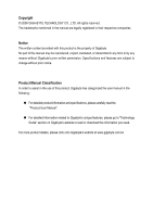
product information and specifications, please carefully read the "Product User Manual". „ For detailed information related to Gigabyte's unique features, please go to "Technology Guide" section on Gigabyte's website to read or download the information you need. For more product details, please - Gigabyte GA-8I915MD-GV | Manual - Page 5
CPU 14 1-3-2 Installation of the Heatsink 15 1-4 Installation of Memory 16 1-5 Installation of Expansion Cards 18 1-5-1 Graphics Card Support List 18 1-6 I/O Back Panel Introduction 20 1-7 Connectors Introduction 21 Chapter 2 BIOS Setup 31 The Main Menu (For example: BIOS Ver. : GA-8I915MD - Gigabyte GA-8I915MD-GV | Manual - Page 6
Information 51 3-5 Contact Us ...51 Chapter 4 Appendix 53 4-1 Unique Software Utilities 53 4-1-1 EasyTune 5 Introduction 54 4-1-2 Xpress Recovery2 Introduction 55 4-1-3 Flash BIOS Method Introduction 57 4-1-4 2 / 4 / 6 Channel Audio Function Introduction 66 4-2 Troubleshooting 72 - 6 - - Gigabyte GA-8I915MD-GV | Manual - Page 7
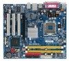
GA-8I915MD-G / GA-8I915MD-GV Motherboard Layout KB_MS ATX_12V LGA775 CPU_FAN ATX CI IDE1 IT8712 COMA GA-8I915MD-G or GA-8I915MD-GV LPT LAN VGA USB DDRII2 PWR_LED F_PANEL USB AUDIO Intel 915G / Intel 915GV PCIE_16 RTL8110S / RTL8100C CD_IN CODEC AUX_IN F_AUDIO SUR_CEN SPDIF_IO - Gigabyte GA-8I915MD-GV | Manual - Page 8
Block Diagram (GA-8I915MD-G) PCI-ECLK (100MHz) LGA775 Processor CPUCLK+/-(200/133MHz) PCI Express x16 VGA PCI Bus RTL8110S RJ45 Host Interface DDRII 600(Note)/533/400MHz DIMM Intel 915G MCH Dual Channel Memory MCHCLK (200/133MHz) 66MHz 33MHz 14.318MHz 48MHz BIOS 2 Serial ATA Intel ATA33/ - Gigabyte GA-8I915MD-GV | Manual - Page 9
Block Diagram (GA-8I915MD-GV) LGA775 Processor CPUCLK+/-(200/133MHz) VGA PCI-ECLK (100MHz) PCI Express x4 PCI Bus RTL8100C RJ45 Host Interface Intel 915GV MCH DDRII 600(Note)533/400MHz DIMM Dual Channel Memory MCHCLK (200/133MHz) 66MHz 33MHz 14.318MHz 48MHz BIOS 2 Serial ATA Intel ATA33/66/ - Gigabyte GA-8I915MD-GV | Manual - Page 10
- 10 - - Gigabyte GA-8I915MD-GV | Manual - Page 11
instructions below: 1. Please turn off the computer and unplug its power cord. 2. When handling the motherboard , avoid touching any metal leads or connectors. 3. It is best to wear an electrostatic discharge (ESD) cuff when handling electronic components (CPU motherboard problem manual - Gigabyte GA-8I915MD-GV | Manual - Page 12
English 1-2 Feature Summary Motherboard CPU Chipset Memory Slots IDE Connections FDD Connections Onboard SATA Peripherals Onboard VGA Onboard LAN Onboard Audio I/O Control Š GA-8I915MD-G or GA-8I915MD-GV Š Supports the latest Intel® Pentium® 4 LGA775 CPU Š Supports 800/533MHz FSB Š L2 cache - Gigabyte GA-8I915MD-GV | Manual - Page 13
System voltage detection Š CPU temperature detection Š CPU / System fan speed detection Š CPU warning temperature Š CPU / System fan failure warning Š CPU smart fan control BIOS Š Use of licensed AWARD BIOS Š Supports Q-Flash Additional Features Š Supports @BIOS Š Supports EasyTune 5 (only - Gigabyte GA-8I915MD-GV | Manual - Page 14
specifications including the CPU, graphics card, memory, hard CPU: An Intel® Pentium 4 Processor with HT Technology - Chipset: An Intel® Chipset that supports HT Technology - BIOS: A BIOS that supports CPU during installation.) GA-8I915MD-G/GA-8I915MD-GV Motherboard - 14 - Fig. 4 Once the CPU - Gigabyte GA-8I915MD-GV | Manual - Page 15
the CPU and make sure the push pins aim to the pin hole on the motherboard.Pressing down the push pins diagonally. Fig. 4 Please make sure the Male and Female push pin are joined closely. (for detailed installation instructions, please refer to the heatsink installation section of the user manual - Gigabyte GA-8I915MD-GV | Manual - Page 16
are unable to insert the module, please switch the direction. The motherboard supports DDR II memory modules, whereby BIOS will automatically detect memory capacity and specifications. Memory modules are designed when you wish to remove the DIMM module. GA-8I915MD-G/GA-8I915MD-GV Motherboard - 16 - - Gigabyte GA-8I915MD-GV | Manual - Page 17
English Dual Channel Memory Configuration The GA-8I915MD-G/GA-8I915MD-GV supports the Dual Channel Technology. After operating the Dual Channel Technology, the bandwidth of Memory Bus will add double. The GA-8I915MD-G/GA-8I915MD-GV includes 2 DIMM sockets. If you want to operate the Dual Channel - Gigabyte GA-8I915MD-GV | Manual - Page 18
.) Figure 1-1. PCI Express x16 Cards Graphics Chip Nvidia Maker Gigabyte Gigabyte Gigabyte Gigabyte Gigabyte Gigabyte Model Name GV-NX53128D GV-NX57128D GV-NX59128D GV-NX62128D GV-NX66256D GV-NX66T128VP "*" Only for GA-8I915MD-GV. GA-8I915MD-G/GA-8I915MD-GV Motherboard - 18 - To be continued - Gigabyte GA-8I915MD-GV | Manual - Page 19
x16 Cards Graphics Chip Nvidia ATi Maker Gigabyte Gigabyte Gigabyte Gigabyte Gigabyte ASUS Gigabyte Gigabyte Gigabyte Gigabyte Gigabyte Gigabyte Gigabyte Gigabyte ASUS ASUS MSI Model Name GV-NX66T128D GV-NX68T256DH GV-NX55128DP GV-NX68U256D GV-NX62TC256D EN6600/TD/128 GV-RX30S128D GV-RX60P128D GV - Gigabyte GA-8I915MD-GV | Manual - Page 20
jack. Line Out Connect the stereo speakers or earphone to this connector. MIC In Microphone can be connected to MIC In jack. You can use audio software to configure 2-/4-/6-channel audio functioning. GA-8I915MD-G/GA-8I915MD-GV Motherboard - 20 - - Gigabyte GA-8I915MD-GV | Manual - Page 21
English 1-7 Connectors Introduction 1 3 17 2 5 6 11 10 9 12 14 8 13 16 4 15 7 18 19 1) ATX_12V 2) ATX (Power Connector) 3) CPU_FAN 4) SYS_FAN 5) FDD 6) IDE1 7) SATA0 / SATA1 8) F_AUDIO 9) PWR_LED 10) F_PANEL 11) CD_IN 12) AUX_IN 13) SPDIF_IO 14) SUR_CEN 15) F_USB1/F_USB2 16) COMB 17) CI - Gigabyte GA-8I915MD-GV | Manual - Page 22
the power connector with its proper location on the motherboard and connect tightly. The ATX_12V power connector mainly supplies power to the CPU. If the ATX_12V power connector is not connected, 12 3.3V(Onlyfor24-pinATX) 24 GND(Only for 24-pin ATX) GA-8I915MD-G/GA-8I915MD-GV Motherboard - 22 - - Gigabyte GA-8I915MD-GV | Manual - Page 23
CPU overheating and failure. 1 CPU_FAN 1 SYS_FAN Pin No. 1 2 3 4 Definition GND +12V Sense Speed Control (Only for CPU_FAN) 5) FDD (Floppy Connector) The FDD connector is used to connect the FDD cable while the other end of the cable connects to the FDD drive. The types of FDD drives supported - Gigabyte GA-8I915MD-GV | Manual - Page 24
on settings, please refer to the instructions located on the IDE device). 40 39 BIOS setting for the Serial ATA and install the proper driver in order to work properly. Pin No. Definition 1 GND 2 TXP 3 TXN 4 GND 1 7 5 RXN 6 RXP 7 GND GA-8I915MD-G/GA-8I915MD-GV Motherboard - Gigabyte GA-8I915MD-GV | Manual - Page 25
To find out if the chassis you are buying support front audio connector, please contact your dealer. Please note, you can have the alternative of using front audio connector or of using rear audio connector to play sound. 2 10 1 9 Pin No. 1 2 3 4 5 6 7 8 9 10 Definition MIC GND MIC_BIAS Power - Gigabyte GA-8I915MD-GV | Manual - Page 26
Hardware System Open: Normal Close: Power On/Off Pin 1: LED anode(+) Pin 2: LED cathode(-) NC 11) CD_IN (CD IN) Connect CD-ROM or DVD-ROM audio out to the connector. Pin No. Definition 1 CD-L 1 2 GND 3 GND 4 CD-R GA-8I915MD-G/GA-8I915MD-GV Motherboard - 26 - - Gigabyte GA-8I915MD-GV | Manual - Page 27
to the connector. Pin No. Definition 1 AUX-L 2 GND 1 3 GND 4 AUX-R 13) SPDIF_IO (SPDIF In/Out) The SPDIF output is capable of providing digital audio to external speakers or compressed AC3 data to an external Dolby Digital Decoder. Use this feature only when your stereo system has digital - Gigabyte GA-8I915MD-GV | Manual - Page 28
, please contact your local dealer. Pin No. Definition 1 Power 9 1 2 Power 10 2 3 USB DX- 4 USB Dy- 5 USB DX+ 6 USB Dy+ 7 GND 8 GND 9 No Pin 10 NC GA-8I915MD-G/GA-8I915MD-GV Motherboard - 28 - - Gigabyte GA-8I915MD-GV | Manual - Page 29
Intrusion, Case Open) This 2-pin connector allows your system to detect if the chassis cover is removed. You can check the "Case Opened" status in BIOS Setup. Pin No. Definition 1 1 Signal 2 GND - 29 - Hardware Installation - Gigabyte GA-8I915MD-GV | Manual - Page 30
same or equivalent type recommended by the manufacturer. Dispose of used batteries according to the manufacturer's instructions. If you want to erase CMOS... 1. Turn OFF the computer and unplug the power . 4. Plug the power cord and turn ON the computer. GA-8I915MD-G/GA-8I915MD-GV Motherboard - 30 - - Gigabyte GA-8I915MD-GV | Manual - Page 31
is a Windows-based utility that does not require users to boot to DOS before upgrading BIOS but directly download and update BIOS from the Internet. CONTROL KEYS Move to select item Select Item Main Menu - Quit and not save changes into CMOS Status Page Setup Menu and Option - Gigabyte GA-8I915MD-GV | Manual - Page 32
your motherboard. The Main Menu (For example: BIOS Ver. : GA-8I915MD-G F3a) Once you enter Award BIOS CMOS Setup Utility, the Main Menu . „ Frequency/Voltage Control This setup page is control CPU clock and frequency ratio. „ Load Fail-Safe Defaults Fail GA-8I915MD-G/GA-8I915MD-GV Motherboard - 32 - - Gigabyte GA-8I915MD-GV | Manual - Page 33
system. „ Save & Exit Setup Save CMOS value settings to CMOS and exit setup. „ Exit Without Saving Abandon all CMOS value changes and exit setup. - 33 - BIOS Setup - Gigabyte GA-8I915MD-GV | Manual - Page 34
` IDE Channel 3 Master Drive A Drive B Floppy 3 Mode Support [None] [None] [None] [None] [1.44M, 3.5"] [None from Sun to Sat, determined by the BIOS and is display only Month The month, start up. • Manual User can manually input the correct settings GA-8I915MD-G/GA-8I915MD-GV Motherboard - 34 - - Gigabyte GA-8I915MD-GV | Manual - Page 35
inch double-sided drive; 2.88M byte capacity. Floppy 3 Mode Support (for Japan Area) Disabled Normal Floppy Drive. (Default value) motherboard. Extended Memory The BIOS determines how much extended memory is present during the POST. This is the amount of memory located above 1 MB in the CPU - Gigabyte GA-8I915MD-GV | Manual - Page 36
access to Setup page if the correct password is not entered at the prompt. (Note) This item will show up when you install a processor that supports this function. GA-8I915MD-G/GA-8I915MD-GV Motherboard - 36 - - Gigabyte GA-8I915MD-GV | Manual - Page 37
mode supported. (Default value) Disabled Disables CPU Hyper XP.(Default value) No-Execute Memory Protect (Note) Enabled Enable No-Execute Memory Protect function.(Default value) Disabled Disable No-Execute Memory Protect function. CPU Enhanced Halt (C1E) (Note) Enabled Enable CPU - Gigabyte GA-8I915MD-GV | Manual - Page 38
Controller USB 2.0 Controller USB Keyboard Support USB Mouse Support AC97 Audio Onboard H/W LAN OnBoard LAN Boot ROM Onboard Serial Port 1 BIOS will auto detect. (Default value) Set On-Chip SATA mode to Combined, you can use up to 4 HDDs on the motherboard GA-8I915MD-G/GA-8I915MD-GV Motherboard - 38 - - Gigabyte GA-8I915MD-GV | Manual - Page 39
Support Enabled Enable USB Mouse Support. Disabled Disable USB Mouse Support. (Default value) AC97 Audio Auto Disabled Auto detect AC97 audio function. (Default value) Disable AC97 audio function. Onboard H/W LAN Enabled Enable Onboard H/W LAN Port 2 Auto BIOS will automatically setup - Gigabyte GA-8I915MD-GV | Manual - Page 40
) : (0~59) Power On By Mouse Disabled Disabled this function. (Default value) Double Click Double click on PS/2 mouse left button to power on the system. GA-8I915MD-G/GA-8I915MD-GV Motherboard - 40 - - Gigabyte GA-8I915MD-GV | Manual - Page 41
IRQ 3,4,5,7,9,10,11,12,14,15 to PCI 2. Auto assign IRQ to PCI 3. (Default value) Set IRQ 3,4,5,7,9,10,11,12,14,15 to PCI 3. - 41 - BIOS Setup - Gigabyte GA-8I915MD-GV | Manual - Page 42
Monitor CPU temperature at 80oC / 176oF. Monitor CPU temperature at 90oC / 194oF. Disable this function. (Default value) CPU/SYSTEM FAN Fail Warning Disabled Disable fan fail warning function. (Default value) Enabled Enable fan fail warning function. GA-8I915MD-G/GA-8I915MD-GV Motherboard - 42 - Gigabyte GA-8I915MD-GV | Manual - Page 43
specifications. With such CPU fans, selecting PWM will not effectively reduce the fan speed. (Note) Whether the CPU Smart FAN Control function is supported will depend on the CPU you install. For more detailed information please check at the FAQ section on GIGABYTE's website. - 43 - BIOS Setup - Gigabyte GA-8I915MD-GV | Manual - Page 44
For Memory Frequency (Mhz) [15X] [Auto] 533 Item Help Menu Level` Set CPU Ratio if CPU Ratio is unlocked KLJI: Move Enter: Select F5: Previous Values +/-/PU/PD: Value This item will show up when you install a processor that supports this function. GA-8I915MD-G/GA-8I915MD-GV Motherboard - 44 - - Gigabyte GA-8I915MD-GV | Manual - Page 45
English 2-8 Load Fail-Safe Defaults CMOS Setup Utility-Copyright (C) 1984-2005 Award Software ` Standard CMOS Features ` Advanced BIOS Features ` Integrated Peripherals ` Power Management Setup ` PnP/PCI Configurations ` PC Health Status ` Frequency/Voltage Control Esc: Quit F8: Q-Flash Load Fail - Gigabyte GA-8I915MD-GV | Manual - Page 46
BIOS Features Menu, you will be prompted for the password every time the system is rebooted or any time you try to enter Setup Menu. If you select "Setup" at "Password Check" in Advance BIOS Features Menu, you will be prompted only when you try to enter Setup. GA-8I915MD-G/GA-8I915MD-GV Motherboard - Gigabyte GA-8I915MD-GV | Manual - Page 47
to Setup Utility. 2-12 Exit Without Saving CMOS Setup Utility-Copyright (C) 1984-2005 Award Software ` Standard CMOS Features ` Advanced BIOS Features ` Integrated Peripherals ` Power Management Setup ` PnP/PCI Configurations ` PC Health Status ` Frequency/Voltage Control Esc: Quit F8: Q-Flash - Gigabyte GA-8I915MD-GV | Manual - Page 48
English GA-8I915MD-G/GA-8I915MD-GV Motherboard - 48 - - Gigabyte GA-8I915MD-GV | Manual - Page 49
will continue to install other drivers. System will reboot automatically after install the drivers, afterward you can install others application. For USB2.0 driver support under Windows XP operating system, please use Windows Service Pack. After install Windows Service Pack, it will show a question - Gigabyte GA-8I915MD-GV | Manual - Page 50
This page displays all the tools that Gigabyte developed and some free software, you can choose anyone you want and press "install" to install them. 3-3 Driver CD Information This page lists the contents of software and drivers in this CD-title. GA-8I915MD-G/GA-8I915MD-GV Motherboard - 50 - - Gigabyte GA-8I915MD-GV | Manual - Page 51
English 3-4 Hardware Information This page lists all device you have for this motherboard. 3-5 Contact Us Please see the last page for details. - 51 - Drivers Installation - Gigabyte GA-8I915MD-GV | Manual - Page 52
English GA-8I915MD-G/GA-8I915MD-GV Motherboard - 52 - - Gigabyte GA-8I915MD-GV | Manual - Page 53
factory defaults to provide a more user-friendly and reliable platform for users. Download Center Download Center allows users to quickly download and update their BIOS as well as the latest drivers for their system. Download Center automatically runs a system check of the user PC and provides the - Gigabyte GA-8I915MD-GV | Manual - Page 54
functions status 9. GIGABYTE Logo Log on to GIGABYTE website 10. Help button Display EasyTuneTM 5 Help file 11. Exit or Minimize button Quit or Minimize EasyTuneTM 5 software (Note) EasyTune 5 functions may vary depending on different motherboards. GA-8I915MD-G/GA-8I915MD-GV Motherboard - 54 - Gigabyte GA-8I915MD-GV | Manual - Page 55
VGA cards How to use the Xpress Recovery2 Initial access by booting from CD-ROM and subsequent access by pressing the F9 key: Steps: After entering BIOS Setup, go to Advanced BIOS Feature and set to boot from CD-ROM. Save the settings and exit the BIOS Setup. Insert the provided driver CD into - Gigabyte GA-8I915MD-GV | Manual - Page 56
and not SATA hard disks on the following motherboards (As this is a BIOS-related issue, it can be solved by BIOS update) GA-K8NXP-9 GA-8N-SLI Royal GA-K8N Ultra-9 GA-8N-SLI Pro GA-K8NF-9 (PCB Ver. 1.0) GA-8N-SLI GA-K8NE (PCB Ver. 1.0) GA-K8NMF-9 GA-8I915MD-G/GA-8I915MD-GV Motherboard - 56 - - Gigabyte GA-8I915MD-GV | Manual - Page 57
Part One. If your motherboard has single-BIOS, please refer to Part Two. Part One: Updating BIOS with Q-FlashTM Utility on Dual BIOS Motherboards. Some of Gigabyte motherboards are equipped with dual BIOS. In the BIOS menu of the motherboards supporting Q-Flash and Dual BIOS, the Q-Flash utility and - Gigabyte GA-8I915MD-GV | Manual - Page 58
Main BIOS from Floppy Load Backup BIOS from Floppy Save Main BIOS to Floppy Save Backup BIOS to Floppy Enter : Run :Move ESC:Reset F10:Power Off Dual BIOS /Dual BIOS utility. Pressing the buttons mentioned on your keyboards to perform these actions. GA-8I915MD-G/GA-8I915MD-GV Motherboard - 58 - - Gigabyte GA-8I915MD-GV | Manual - Page 59
and press Enter. In this example, we only download one BIOS file to the floppy disk so only one BIOS file, 8KNXPU.Fba, is listed. Please confirm again you have the correct BIOS file for your motherboard. Dual BIOS Utility Boot From Main Bios Main ROM Type/Size SST 49LF003A Backup ROM Type/Size - Gigabyte GA-8I915MD-GV | Manual - Page 60
flashing BIOS. 4. Press any keys to return to the Q-Flash menu when the BIOS updating procedure is completed. Dual BIOS Utility Boot From Main Bios Main ROM to enter SETUP / Dual BIOS / Q-Flash / F9 For Xpress Recovery 09/23/2003-i875P-6A79BG03C-00 GA-8I915MD-G/GA-8I915MD-GV Motherboard - 60 - - Gigabyte GA-8I915MD-GV | Manual - Page 61
Disk Type... Press Y on your keyboard to save and exit. Part Two: Updating BIOS with Q-FlashTM Utility on Single-BIOS Motherboards. This part guides users of single-BIOS motherboards how to update BIOS using the Q-FlashTM utility. CMOS Setup Utility-Copyright (C) 1984-2004 Award Software Standard - Gigabyte GA-8I915MD-GV | Manual - Page 62
F10:Power Off Do not trun off power or reset your system at this stage!! After BIOS file is read, you'll see a confirmation dialog box asking you "Are you sure to update BIOS?" Please do not take out the floppy disk when it begins flashing BIOS. GA-8I915MD-G/GA-8I915MD-GV Motherboard - 62 - - Gigabyte GA-8I915MD-GV | Manual - Page 63
screen becomes the one you flashed. The BIOS file becomes F4 after updating Award Modular BIOS v6.00PG, An Energy Star Ally Copyright (C) 1984-2003, Award Software, Inc. Intel 845GE AGPSet BIOS for 8GE800 F4 Check System Health OK Main Processor : Intel Pentium(R) 4 1.7GHz (100x17.0) - Gigabyte GA-8I915MD-GV | Manual - Page 64
"Update New BIOS" c. Please select "All Files" in dialog box while opening the old file. d. Please search for BIOS unzip file, downloading from internet or any other methods (such as: 8I915MDG.E2). e. Complete update process following the instruction. GA-8I915MD-G/GA-8I915MD-GV Motherboard - 64 - Gigabyte GA-8I915MD-GV | Manual - Page 65
II, be sure that motherboard's model name in BIOS unzip file are the same as your motherboard's. Otherwise, your system won't boot. III. In method I, if the BIOS file you need cannot be found in @BIOSTM server, please go onto Gigabyte's web site for downloading and updating it according to method - Gigabyte GA-8I915MD-GV | Manual - Page 66
driver, you'll find a Sound Effect icon on the lower right hand taskbar. Click the icon to select the function. STEP 3: On the AC97 Audio Configuration menu, click the Speaker Configuration tab and select the 2-channel mode for stereo speaker output check box. GA-8I915MD-G/GA-8I915MD-GV Motherboard - Gigabyte GA-8I915MD-GV | Manual - Page 67
Out," the rear channels to "Line In." STEP 2: After installing the audio driver, you'll find a Sound Effect icon on the lower right hand taskbar. Click the icon to select the function. STEP 3: On the AC97 Audio Configuration menu, click the Speaker Configuration tab and select the 4-channel mode - Gigabyte GA-8I915MD-GV | Manual - Page 68
the audio driver, you'll find a Sound Effect icon on the lower Audio Output Mode Notes: When the Environment setting is None, the sound would be performed as stereo mode (2-channel output). Please select the other settings for 6 channels output. Line In GA-8I915MD-G/GA-8I915MD-GV Motherboard - Gigabyte GA-8I915MD-GV | Manual - Page 69
. It is the best solution if you need 6 channel output, Line In and MIC at the same time. "SURROUND-KIT" is included in the GIGABYTE unique "Audio Combo Kit" as picture. STEP 1: Secure the metal bracket of the "Surround Kit" to the chassis back panel with a screw. STEP 2: Connect the "SURROUND - Gigabyte GA-8I915MD-GV | Manual - Page 70
4: After installing the audio driver, you'll find a Sound Effect icon on the Audio Output Mode Notes: When the Environment setting is None, the sound would be performed as stereo mode (2-channel output). Please select the other settings for 6 channels output. GA-8I915MD-G/GA-8I915MD-GV Motherboard - Gigabyte GA-8I915MD-GV | Manual - Page 71
bracket of the SPDIF Output device to the chassis back panel with a screw. STEP 2: Connect the SPDIF device cable to the SPDIF_IO connector on the motherboard. STEP 3: Connect SPDIF to the SPDIF decoder. - 71 - Appendix English - Gigabyte GA-8I915MD-GV | Manual - Page 72
English 4-2 Troubleshooting Below is a collection of general asked questions. To check general asked questions based on a specific motherboard model, please log on to www.gigabyte.com.tw Question 1: I cannot see some options that were included in previous BIOS after updating BIOS. Why? Answer: - Gigabyte GA-8I915MD-GV | Manual - Page 73
- 73 - Appendix English - Gigabyte GA-8I915MD-GV | Manual - Page 74
English GA-8I915MD-G/GA-8I915MD-GV Motherboard - 74 - - Gigabyte GA-8I915MD-GV | Manual - Page 75
- 75 - Appendix English - Gigabyte GA-8I915MD-GV | Manual - Page 76
English GA-8I915MD-G/GA-8I915MD-GV Motherboard - 76 - - Gigabyte GA-8I915MD-GV | Manual - Page 77
- 77 - Appendix English - Gigabyte GA-8I915MD-GV | Manual - Page 78
English GA-8I915MD-G/GA-8I915MD-GV Motherboard - 78 - - Gigabyte GA-8I915MD-GV | Manual - Page 79
.giga-byte.com U.S.A. G.B.T. INC. TEL: +1-626-854-9338 FAX: +1-626-854-9339 Tech. Support : http://tw.giga-byte.com/TechSupport/ServiceCenter.htm Non-Tech. Support(Sales/Marketing) : http://ggts.gigabyte.com.tw/nontech.asp WEB address : http://www.giga-byte.com Germany G.B.T. TECHNOLOGY TRADING GMBH - Gigabyte GA-8I915MD-GV | Manual - Page 80
Representative Office Of GIGA-BYTE Technology Co., Ltd. in Romania Tech. Support : http://tw.giga-byte.com/TechSupport/ServiceCenter.htm Non-Tech. Support(Sales/Marketing) : http://ggts.gigabyte.com.tw/nontech.asp WEB address: http://www.gigabyte.com.ro GA-8I915MD-G/GA-8I915MD-GV Motherboard - 80 -
-
 1
1 -
 2
2 -
 3
3 -
 4
4 -
 5
5 -
 6
6 -
 7
7 -
8
-
9
-
10
-
11
-
12
-
13
-
14
-
15
-
16
-
17
-
18
-
19
-
20
-
21
-
22
-
23
-
24
-
25
-
26
-
27
-
28
-
29
-
30
-
31
-
32
-
33
-
34
-
35
-
36
-
37
-
38
-
39
-
40
-
41
-
42
-
43
-
44
-
45
-
46
-
47
-
48
-
49
-
50
-
51
-
52
-
53
-
54
-
55
-
56
-
57
-
58
-
59
-
60
-
61
-
62
-
63
-
64
-
65
-
66
-
67
-
68
-
69
-
70
-
71
-
72
-
73
-
74
-
75
-
76
-
77
-
78
-
79
-
80
 |
 |

GA-8I915MD-G/
GA-8I915MD-GV
Intel
®
Pentium
®
4 LGA775 Processor Motherboard
User's Manual
Rev. 1003
12ME-8I915MDS-1003R