Gigabyte GA-8I915ME-C Manual
Gigabyte GA-8I915ME-C Manual
 |
View all Gigabyte GA-8I915ME-C manuals
Add to My Manuals
Save this manual to your list of manuals |
Gigabyte GA-8I915ME-C manual content summary:
- Gigabyte GA-8I915ME-C | Manual - Page 1
GA-8I915ME Series Intel® Pentium® 4 LGA775 Processor Motherboard User's Manual Rev. 1003 12ME-I915MES-1003 * The WEEE marking on the product indicates this product must not be disposed of with user's other household waste and must - Gigabyte GA-8I915ME-C | Manual - Page 2
Motherboard GA-8I915ME May 27, 2005 Motherboard GA-8I915ME May 27, 2005 - Gigabyte GA-8I915ME-C | Manual - Page 3
following: „ For detailed product information and specifications, please carefully read the "Product User Manual". „ For detailed information related to Gigabyte's unique features, please go to "Technology Guide" section on Gigabyte's website to read or download the information you need. For more - Gigabyte GA-8I915ME-C | Manual - Page 4
Table of Content GA-8I915ME Series Motherboard Layout 6 Block Diagram ...7 Chapter 1 Hardware Installation 9 1-1 Considerations Prior to Installation 9 1-2 Feature Summary 10 1-3 Installation of the CPU and Heatsink 12 1-3-1 Installation of the CPU 12 1-3-2 Installation of the Heatsink 13 1-4 - Gigabyte GA-8I915ME-C | Manual - Page 5
Chapter 4 Appendix ...55 4-1 Unique Software Utilities 55 4-1-1 EasyTune 5 Introduction 56 4-1-2 Xpress Recovery2 Introduction 57 4-1-3 Flash BIOS Method Introduction 60 4-1-4 2- / 4- / 6- Channel Audio Function Introduction 69 4-1-5 Jack-Sensing Introduction 75 4-2 Troubleshooting 77 - 5 - - Gigabyte GA-8I915ME-C | Manual - Page 6
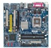
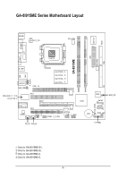
GA-8I915ME Series Motherboard Layout IT8712F CI KB_MS ATX_12V CPU_FAN COM1 LPT GA-8I915ME ATX SYS_FAN FDD VGA LGA775 R_USB LAN USB F_AUDIO AUDIO1 SUR_CEN PCIE_16 Intel 915GV Intel 915GL Intel 910GL Intel 915G DIMM1 DIMM2 IDE RTL8100C RTL8110S PCI1 GEAR ICH6 -C -G -GL -GV PCI2 - Gigabyte GA-8I915ME-C | Manual - Page 7
Diagram VGA LGA775 Processor CPUCLK+/-( USB Ports 24MHz 33MHz PS/2 KB/Mouse PCICLK (33MHz) MIC Line-Out Line-In SPDIF In SPDIF Out Only for GA-8I915ME-GV. Only for GA-8I915ME-GL. Only for GA-8I915ME-C. Only for GA-8I915ME-G. (Note) - 7 - GA-8I915ME-GV / GA-8I915ME-GL / GA-8I915ME-C supports - Gigabyte GA-8I915ME-C | Manual - Page 8
- 8 - - Gigabyte GA-8I915ME-C | Manual - Page 9
instructions below: 1. Please turn off the computer and unplug its power cord. 2. When handling the motherboard , avoid touching any metal leads or connectors. 3. It is best to wear an electrostatic discharge (ESD) cuff when handling electronic components (CPU, RAM a problem related manual. - Gigabyte GA-8I915ME-C | Manual - Page 10
English 1-2 Feature Summary Motherboard CPU Š GA-8I915ME Series motherboard -GA-8I915ME-GV / GA-8I915ME-GL / GA-8I915ME-C / GA-8I915ME-G Š Supports the latest Intel® Pentium® 4 LGA775 CPU Š Supports 800 / 533MHz FSB Š L2 cache varies with CPU Chipset Memory Slots IDE Connections FDD - Gigabyte GA-8I915ME-C | Manual - Page 11
will instead be shown as 3.xxGB memory during system startup. GA-8I915ME-C(910GL chipset) only supports up to 2GB memory. (Note 2) GA-8I915ME-GV / GA-8I915ME-GL / GA-8I915ME-C supports transfer up to PCI Express x4 mode. GA-8I915ME-G supports transfer up to PCI Express x16 mode. (Note 3) Please - Gigabyte GA-8I915ME-C | Manual - Page 12
- CPU: An Intel® Pentium 4 Processor with HT Technology - Chipset: An Intel® Chipset that supports HT Technology - BIOS: A BIOS that supports HT that might cause damage to the CPU during installation.) GA-8I915ME Series Motherboard - 12 - Fig. 4 Once the CPU is properly inserted, please replace - Gigabyte GA-8I915ME-C | Manual - Page 13
the CPU and make sure the push pins aim to the pin hole on the motherboard.Pressing down the push pins diagonally. Fig. 4 Please make sure the Male and Female push pin are joined closely. (for detailed installation instructions, please refer to the heatsink installation section of the user manual - Gigabyte GA-8I915ME-C | Manual - Page 14
insert the module, please switch the direction. The motherboard supports DDR memory modules, whereby BIOS will automatically detect memory capacity and specifications. Memory modules are designed so that they can steps when you wish to remove the DIMM module. GA-8I915ME Series Motherboard - 14 - - Gigabyte GA-8I915ME-C | Manual - Page 15
GV/GA-8I915ME-GL/GA-8I915ME-C/GA-8I915ME-G includes 2 DIMM sockets, and each Channel has two DIMM sockets as following: Channel A : DIMM1 Channel B : DIMM2 If you want to operate the Dual Channel Technology, please note the following explanations due to the limitation of Intel chipset specifications - Gigabyte GA-8I915ME-C | Manual - Page 16
instruction BIOS utility of expansion card from BIOS. 8. Install related driver VGA card. Please align the VGA card to the onboard PCI Express x 16/G.E.A.R. slot and press firmly down on the slot .Make sure your VGA card is locked by the small whitedrawable bar. GA-8I915ME Series Motherboard - Gigabyte GA-8I915ME-C | Manual - Page 17
supported under the Windows XP operating system. When using an add-on graphics card, please first delete the onboard graphics driver before installing the driver for the add-on graphics card.) Figure 1-1. 4X AGP Card Graphics Chip Nvidia Maker Gigabyte Gigabyte Gigabyte Gigabyte Model Name GA - Gigabyte GA-8I915ME-C | Manual - Page 18
Gigabyte Gigabyte Gigabyte Gigabyte Gigabyte Gigabyte Gigabyte Gigabyte Gigabyte ASUS GA-8I915ME Series Motherboard Model Name GV-AR64DL-T-SI GV-AR64S-H GV-AP64D GV-AP64DH GV-AP128DG-H GV-AF128D-GH SiS315 64MB V3500 Model Name GV-N57L128D G V-N59X128D V9180TD V9480-TVD V9520 MX440-VTD8X MS - Gigabyte GA-8I915ME-C | Manual - Page 19
x16 Card Graphics Chip ATi Maker Gigabyte Gigabyte Gigabyte Gigabyte Gigabyte Gigabyte Gigabyte Gigabyte ASUS ASUS MSI Model Name GV-RX30S128D GV-RX60P128D GV-RX60X128V GV-RX70128D GV-RX70P128D GV-RX80T256V G V-RX80L256V G V-RX80256D AX800XT AX700PRO RX600 XT-TD128 - 19 - Hardware Installation - Gigabyte GA-8I915ME-C | Manual - Page 20
surround speakers to this connector. MIC In Microphone can be connected to MIC In jack. You can use audio software to configure 2-/4-/6- channel audio functioning. Only for GA-8I915ME-GV. Only for GA-8I915ME-GL. Only for GA-8I915ME-C. Only for GA-8I915ME-G. GA-8I915ME Series Motherboard - 20 - - Gigabyte GA-8I915ME-C | Manual - Page 21
English 1-7 Connectors Introduction 1 3 2 18 5 4 6 11 16 20 7 19 10 8 12 13 17 15 9 14 21 1) ATX_12V 2) ATX (Power Connector) 3) CPU_FAN 4) SYS_FAN 5) FDD 6) IDE 7) SATA0 / SATA2 8) F_PANEL 9) WOL 10) PWR_LED 11) F_AUDIO 12) CD_IN 13) AUX_IN 14) F_USB1 / F_USB2 15) COM2 16) SUR_CEN 17) - Gigabyte GA-8I915ME-C | Manual - Page 22
proper location on the motherboard and connect tightly. The ATX_12V power connector mainly supplies power to the CPU. If the ATX_12V remove it. Pin No. Definition 3 4 1 GND 1 2 2 GND 3 +12V 4 +12V GA-8I915ME Series Motherboard 13 24 - 22 - Pin No. 1 1 2 3 4 5 6 7 8 9 10 - Gigabyte GA-8I915ME-C | Manual - Page 23
CPU overheating and failure. 1 CPU_FAN 1 SYS_FAN Pin No. 1 2 3 4 Definition GND +12V Sense Speed Control (Only for CPU_FAN) 5) FDD (Floppy Connector) The FDD connector is used to connect the FDD cable while the other end of the cable connects to the FDD drive. The types of FDD drives supported - Gigabyte GA-8I915ME-C | Manual - Page 24
for information on settings, please refer to the instructions located on the IDE device). 40 39 BIOS setting for the Serial ATA and install the proper driver in order to work properly. Pin No. Definition 1 GND 1 7 2 TXP 3 TXN 4 GND 5 RXN 6 RXP 7 GND GA-8I915ME Series Motherboard - Gigabyte GA-8I915ME-C | Manual - Page 25
English 8) F_PANEL (Front Panel Jumper) Please connect the power LED, PC speaker, reset switch and power switch etc of your chassis front panel to the F_PANEL connector according to the pin assignment below. Message LED/ Power/ Sleep LED Power Switch Speaker Connector SPEAK- SPEAK+ PWPW+ MSGMSG - Gigabyte GA-8I915ME-C | Manual - Page 26
to use "Front Audio" connector, you must remove the jumpers on pin 5-6, 9-10. Pin No. Definition 1 MIC 10 9 2 GND 3 MIC_BIAS 4 POWER 2 1 5 FrontAudio(R) 6 Rear Audio (R)/ Return R 7 NC 8 No Pin 9 FrontAudio (L) 10 Rear Audio (L)/ Return L GA-8I915ME Series Motherboard - 26 - - Gigabyte GA-8I915ME-C | Manual - Page 27
English 12) CD_IN (CD IN) Connect CD-ROM or DVD-ROM audio out to the connector. Pin No. Definition 1 CD-L 1 2 GND 3 GND 4 CD -R 13) AUX_IN (AUX In Connector) Connect other device (such as PCI TV Tuner audio out) to the connector. Pin No. Definition 1 AUX-L 1 2 GND 3 GND 4 AUX-R - Gigabyte GA-8I915ME-C | Manual - Page 28
it. For optional front USB cable, please contact your local dealer. Pin No. Definition 1 Power 2 Power 9 1 3 USB DX- 4 USB Dy- 10 2 5 USB DX+ 6 USB Dy+ 7 GND 4 NDTR B- 1 9 5 GND 6 NDSR B- 7 NRTS B- 8 NCTS B- 9 NRI B- 10 No Pin GA-8I915ME Series Motherboard - 28 - - Gigabyte GA-8I915ME-C | Manual - Page 29
Definition SUR OUTL SUR OUTR GND No Pin CENTER_OUT BASS_OUT 17) SPDIF_IO (SPDIF In/ Out) The SPDIF output is capable of providing digital audio to external speakers or compressed AC3 data to an external Dolby Digital Decoder. Use this feature only when your stereo system has digital input function - Gigabyte GA-8I915ME-C | Manual - Page 30
your system to detect if the chassis cover is removed. You can check the "Case Opened" status in BIOS Setup. Pin No. Definition 1 1 Signal 2 GND 19) CLR_CMOS (Clear CMOS) You may clear the from improper use this jumper. 1 Open: Normal 1 Short :Clear CMOS GA-8I915ME Series Motherboard - 30 - - Gigabyte GA-8I915ME-C | Manual - Page 31
English 20) BIOS_WP (BIOS Write Protect) 1 Open: Normal 1 Short :Write Protect 21) BAT(Battery) If you want to erase CMOS... 1.Turn the same or equivalent type recommended by the manufacturer. Dispose of used batteries according to the manufacturer's instructions. - 31 - Hardware Installation - Gigabyte GA-8I915ME-C | Manual - Page 32
English GA-8I915ME Series Motherboard - 32 - - Gigabyte GA-8I915ME-C | Manual - Page 33
allows the user to quickly and easily update or backup BIOS without entering the operating system. @BIOS is a Windows-based utility that does not require users to boot to DOS before upgrading BIOS but directly download and update BIOS from the Internet. CONTROL KEYS Enter> - Gigabyte GA-8I915ME-C | Manual - Page 34
described in this chapter are for reference only and may differ from the exact settings for your motherboard. The Main Menu (For example: GA-8I915ME-GV / BIOS Ver.: F2) Once you enter Award BIOS CMOS Setup Utility, the Main Menu (as figure below) will appear on the screen. Use arrow keys to select - Gigabyte GA-8I915ME-C | Manual - Page 35
system. „ Save & Exit Setup Save CMOS value settings to CMOS and exit setup. „ Exit Without Saving Abandon all CMOS value changes and exit setup. - 35 - BIOS Setup - Gigabyte GA-8I915ME-C | Manual - Page 36
hh:mm:ss) CMOS Setup Utility-Copyright (C) 1984-2005 Award Week The week, from Sun to Sat, determined by the BIOS and is display only Month The month, Jan. Through Dec automatic Manual detection step and allow for faster system start up. User can manually GA-8I915ME Series Motherboard - 36 - - Gigabyte GA-8I915ME-C | Manual - Page 37
88M byte capacity. Floppy 3 Mode Support (for Japan Area) Disabled Normal be prompted. Whenever the BIOS detects a non-fatal error the BIOS. Base Memory The POST of the BIOS will motherboard, or 640K for systems with 640K or more memory installed on the motherboard. Extended Memory The BIOS - Gigabyte GA-8I915ME-C | Manual - Page 38
will not access to Setup page if the correct password is not entered at the prompt. (Note3) This item will show up when you install a processor which supports this function. GA-8I915ME Series Motherboard - 38 - - Gigabyte GA-8I915ME-C | Manual - Page 39
. (Note2) GA-8I915ME-GV / GA-8I915ME-GL / GA-8I915ME-C supports transfer up to PCI Express x4 mode; BIOS item will display "PEG2". GA-8I915ME-G supports transfer up to PCI Express x16 mode; BIOS item will display "PEG". (Note3) This item will show up when you install a processor which supports this - Gigabyte GA-8I915ME-C | Manual - Page 40
Enabled Disabled Enable USB Controller. (Default value) Disable USB Controller. USB 2.0 Controller Disable this function if you are not using onboard USB 2.0 feature. Enabled Enable USB 2.0 Controller. (Default value) Disabled Disable USB 2.0 Controller. GA-8I915ME Series Motherboard - 40 - - Gigabyte GA-8I915ME-C | Manual - Page 41
USB Keyboard Support Enabled Enable USB Keyboard Support. Disabled Disable USB Keyboard Support. (Default value) USB Mouse Support Enabled Enable USB Mouse Support. Disabled Disable USB Mouse Support. (Default value) AC97 Audio Auto Disabled Auto detect AC97 audio Auto BIOS will - Gigabyte GA-8I915ME-C | Manual - Page 42
Management Setup CMOS Setup Utility-Copyright (C) 1984-2005 Suspend). (Default value) S3(STR) Set ACPI suspend type to S3/STR(Suspend To RAM). Soft-off by PWR-BTTN Instant-off Press power button then Power off instantly. (Default to power on the system. GA-8I915ME Series Motherboard - 42 - - Gigabyte GA-8I915ME-C | Manual - Page 43
always in "On" state. Memory When AC-power back to the system, the system will return to the Last state before AC-power off. - 43 - BIOS Setup - Gigabyte GA-8I915ME-C | Manual - Page 44
Utility-Copyright (C) 1984-2005 CPU Smart FAN Mode [Disabled] Yes OK OK OK OK 33oC 4687 RPM 0 RPM [Disabled] [Disabled] [Disabled] [Enabled] [Auto] Item Help Menu Level` KLJI: Move Enter: Select F5: Previous Values +/-/PU/PD: Value F10: Save F6: Fail-Save Default GA-8I915ME Series Motherboard - Gigabyte GA-8I915ME-C | Manual - Page 45
cable. Note: In fact, the Voltage option can be used for CPU fans with 3-pin or 4-pin power cables. However, some 4-pin CPU fan power cables are not designed following Intel 4-Wire fans PWM control specifications. With such CPU fans, selecting PWM will not effectively reduce the fan speed. - 45 - Gigabyte GA-8I915ME-C | Manual - Page 46
English 2-7 Frequency/Voltage Control CMOS Setup Utility-Copyright (C) 1984-2005 Award Software Frequency/Voltage Control CPU Clock Ratio Memory Frequency for Memory Frequency (Mhz item will show up when you install a processor which supports this function. GA-8I915ME Series Motherboard - 46 - - Gigabyte GA-8I915ME-C | Manual - Page 47
2-9 Load Optimized Defaults CMOS Setup Utility-Copyright (C) 1984-2005 Award Software ` Standard CMOS Features ` Advanced BIOS Features ` Integrated Peripherals ` Power Selecting this field loads the factory defaults for BIOS and Chipset Features which the system automatically detects. - 47 - Gigabyte GA-8I915ME-C | Manual - Page 48
Advance BIOS Features Menu, you will be prompted for the password every time the system is rebooted or any time you try to enter Setup Menu. If you select "Setup" at "Password Check" in Advance BIOS Features Menu, you will be prompted only when you try to enter Setup. GA-8I915ME Series Motherboard - Gigabyte GA-8I915ME-C | Manual - Page 49
save the user setup value to RTC CMOS. Type "N" will return to Setup Utility. 2-12 Exit Without Saving CMOS Setup Utility-Copyright (C) 1984-2005 Award Software ` Standard CMOS Features ` Advanced BIOS Features ` Integrated Peripherals ` Power Management Setup ` PnP/PCI Configurations ` PC Health - Gigabyte GA-8I915ME-C | Manual - Page 50
English GA-8I915ME Series Motherboard - 50 - - Gigabyte GA-8I915ME-C | Manual - Page 51
shown in Windows XP. Insert the driver CD-title that came with your motherboard into your CD-ROM drive, the driver CD-title will auto start and show the installation guide. If not, please double click the CD-ROM device icon in "My computer", and execute the Run.exe. 3-1 Install Chipset Drivers After - Gigabyte GA-8I915ME-C | Manual - Page 52
This page displays all the tools that Gigabyte developed and some free software, you can choose anyone you want and press "install" to install them. 3-3 Driver CD Information This page lists the contents of software and drivers in this CD-title. GA-8I915ME Series Motherboard - 52 - - Gigabyte GA-8I915ME-C | Manual - Page 53
English 3-4 Hardware Information This page lists all device you have for this motherboard. 3-5 Contact Us Please see the last page for details. - 53 - Install Drivers - Gigabyte GA-8I915ME-C | Manual - Page 54
English GA-8I915ME Series Motherboard - 54 - - Gigabyte GA-8I915ME-C | Manual - Page 55
factory defaults to provide a more user-friendly and reliable platform for users. Download Center Download Center allows users to quickly download and update their BIOS as well as the latest drivers for their system. Download Center automatically runs a system check of the user PC and provides the - Gigabyte GA-8I915ME-C | Manual - Page 56
Windows based system performance enhancement and manageability utility. Featuring several powerful yet easy to use tools such as 1) Overclocking for enhancing system performance, 2) C.I.A. and M.I.B. for special enhancement for CPU on different motherboards. GA-8I915ME Series Motherboard - 56 - - Gigabyte GA-8I915ME-C | Manual - Page 57
English 4-1-2 Xpress Recovery2 Introduction Xpress Recovery2 is designed to provide quick backup and restoration of hard disk data. Supporting Microsoft operating systems including Windows XP/2000/NT/98/Me and DOS, and file systems including FAT16, FAT32, and NTFS, Xpress Recovery2 is able to back - Gigabyte GA-8I915ME-C | Manual - Page 58
motherboards (As this is a BIOS-related issue, it can be solved by BIOS update) GA-K8U GA-K8U-9 GA-K8NXP-SLI GA-K8N Ultra-SLI GA-K8N Pro-SLI GA-K8NXP-9 GA-K8N Ultra-9 GA-K8NF-9 (PCB Ver. 1.0) GA-K8NE (PCB Ver. 1.0) GA-K8NMF-9 GA-8N-SLI Royal GA-8N-SLI Pro GA-8N-SLI GA-8I915ME Series Motherboard - Gigabyte GA-8I915ME-C | Manual - Page 59
with dual BIOS. In the BIOS menu of the motherboards supporting Q-Flash and Dual BIOS, the Q-Flash utility and Dual BIOS utility are combined in the same screen. This section only deals with how to use Q-Flash utility. In the following sections, we take GA-8KNXP Ultra as the example to guide you how - Gigabyte GA-8I915ME-C | Manual - Page 60
Enter key on your keyboard to enable execution of the task. Action bar: Contains the names of four actions needed to operate the Q-Flash/Dual BIOS utility. Pressing the buttons mentioned on your keyboards to perform these actions. GA-8I915ME Series Motherboard - 60 - - Gigabyte GA-8I915ME-C | Manual - Page 61
flash and press Enter. In this example, we only download one BIOS file to the floppy disk so only one BIOS file, 8KNXPU.Fba, is listed. Please confirm again you have the correct BIOS file for your motherboard. Dual BIOS Utility Boot From Main Bios Main ROM Type/Size SST 49LF003A Backup ROM Type - Gigabyte GA-8I915ME-C | Manual - Page 62
begins flashing BIOS. 4. Press any keys to return to the Q-Flash menu when the BIOS updating procedure is completed. Dual BIOS Utility Boot From Main Bios Main ROM DEL to enter SETUP / Dual BIOS / Q-Flash / F9 For Xpress Recovery 09/23/2003-i875P-6A79BG03C-00 GA-8I915ME Series Motherboard - 62 - - Gigabyte GA-8I915ME-C | Manual - Page 63
your keyboard to save and exit. Part Two: Updating BIOS with Q-FlashTM Utility on Single-BIOS Motherboards. This part guides users of single-BIOS motherboards how to update BIOS using the Q-FlashTM utility. CMOS Setup Utility-Copyright (C) 1984-2004 Award Software Standard CMOS Features Advanced - Gigabyte GA-8I915ME-C | Manual - Page 64
:tRemeset F10:Power Off Do not trun off power or reset your system at this stage!! After BIOS file is read, you'll see a confirmation dialog box asking you "Are you sure to update BIOS?" Please do not take out the floppy disk when it begins flashing BIOS. GA-8I915ME Series Motherboard - 64 - - Gigabyte GA-8I915ME-C | Manual - Page 65
keys to return to the Q-Flash menu when the BIOS updating procedure is completed. Q-Flash Utility V1.30 Flash Type/Size SST 49LF003A 256K Enter 1984-2003, Award Software, Inc. Intel 845GE AGPSet BIOS for 8GE800 F4 Check System Health OK Main Processor : Intel Pentium(R) 4 1.7GHz (100x17.0) - Gigabyte GA-8I915ME-C | Manual - Page 66
b. Click "Update New BIOS" c. Please select "All Files" in dialog box while opening the old file. d. Please search for BIOS unzip file, downloading from internet or any other methods (such as: 8I915ME.F2). e. Complete update process following the instruction. GA-8I915ME Series Motherboard - 66 - - Gigabyte GA-8I915ME-C | Manual - Page 67
In method II, be sure that motherboard's model name in BIOS unzip file are the same as your motherboard's. Otherwise, your system won't boot. III. In method I, if the BIOS file you need cannot be found in @BIOSTM server, please go onto Gigabyte's web site for downloading and updating it according to - Gigabyte GA-8I915ME-C | Manual - Page 68
audio driver, you'll find a Sound Effect icon on the lower right hand taskbar. Click the icon to select the function. STEP 3: On the AC97 Audio Configuration menu, click the Speaker Configuration tab and select the 2-channel mode for stereo speaker output check box. GA-8I915ME Series Motherboard - Gigabyte GA-8I915ME-C | Manual - Page 69
Out," the rear channels to "Line In." STEP 2: After installing the audio driver, you'll find a Sound Effect icon on the lower right hand taskbar. Click the icon to select the function. STEP 3: On the AC97 Audio Configuration menu, click the Speaker Configuration tab and select the 4-channel mode - Gigabyte GA-8I915ME-C | Manual - Page 70
STEP 2: After installing the audio driver, you'll find a Sound Effect icon on the lower right Audio Configuration menu, click the Speaker Configuration tab and select the 6-channel mode for 5.1 speaker output check box. Clear the Only SURROUND-KIT check box and press OK. GA-8I915ME Series Motherboard - Gigabyte GA-8I915ME-C | Manual - Page 71
is the best solution if you need 6 channel output, Line In and MIC at the same time. "SURROUND-KIT" is included in the GIGABYTE unique "Audio Combo Kit" as picture. STEP 1: Secure the metal bracket of the"Surround Kit" to the chassis back panel with a screw. STEP 2: Connect the "SURROUND-KIT - Gigabyte GA-8I915ME-C | Manual - Page 72
STEP 4: After installing the audio driver, you'll find a Sound Effect icon on the lower Audio Output Mode Notes: When the Environment setting is None, the sound would be performed as stereo mode (2-channel output). Please select the other settings for 6 channels output. GA-8I915ME Series Motherboard - Gigabyte GA-8I915ME-C | Manual - Page 73
bracket of the SPDIF Output device to the chassis back panel with a screw. STEP 2: Connect the SPDIF device cable to the SPDIF_IO connector on the motherboard. STEP 3: Connect SPDIF to the SPDIF decoder. - 73 - Appendix English - Gigabyte GA-8I915ME-C | Manual - Page 74
Out jack, and microphone to MIC In jack. Auto-detecting: Please connect the devices to the right jacks as above. A window will appear as right picture if you setup the devices properly. Please note that 3D audio function will only appear when 3D audio inputs. GA-8I915ME Series Motherboard - 74 - - Gigabyte GA-8I915ME-C | Manual - Page 75
English If you set wrong with the connectors, the warning message will come out as right picture. Manual setting: If the device picture shows different from what you set, please press "Manual Selection" to set. - 75 - Appendix - Gigabyte GA-8I915ME-C | Manual - Page 76
or display card error 1 long 3 short: Keyboard error 9 beeps ROM checksum error 1 long 9 short: BIOS ROM error 10 beeps CMOS shutdown register read/write error Continuous long beeps: DRAM error 11 beeps Cache memory bad Continuous short beeps: Power error GA-8I915ME Series Motherboard - 76 - - Gigabyte GA-8I915ME-C | Manual - Page 77
- 77 - Appendix English - Gigabyte GA-8I915ME-C | Manual - Page 78
English GA-8I915ME Series Motherboard - 78 - - Gigabyte GA-8I915ME-C | Manual - Page 79
: No.6, Bau Chiang Road, Hsin-Tien, Taipei 231, Taiwan TEL: +886-2-8912-4888 FAX: +886-2-8912-4003 Tech. Support : http://tw.giga-byte.com/TechSupport/ServiceCenter.htm Non-Tech. Support(Sales/Marketing) : http://ggts.gigabyte.com.tw/nontech.asp WEB address (English): http://www.gigabyte.com.tw WEB - Gigabyte GA-8I915ME-C | Manual - Page 80
Romania Representative Office Of GIGA-BYTE Technology Co., Ltd. in Romania Tech. Support : http://tw.giga-byte.com/TechSupport/ServiceCenter.htm Non-Tech. Support(Sales/Marketing) : http://ggts.gigabyte.com.tw/nontech.asp WEB address: http://www.gigabyte.com.ro GA-8I915ME Series Motherboard - 80 -
-
 1
1 -
 2
2 -
 3
3 -
 4
4 -
 5
5 -
 6
6 -
 7
7 -
8
-
9
-
10
-
11
-
12
-
13
-
14
-
15
-
16
-
17
-
18
-
19
-
20
-
21
-
22
-
23
-
24
-
25
-
26
-
27
-
28
-
29
-
30
-
31
-
32
-
33
-
34
-
35
-
36
-
37
-
38
-
39
-
40
-
41
-
42
-
43
-
44
-
45
-
46
-
47
-
48
-
49
-
50
-
51
-
52
-
53
-
54
-
55
-
56
-
57
-
58
-
59
-
60
-
61
-
62
-
63
-
64
-
65
-
66
-
67
-
68
-
69
-
70
-
71
-
72
-
73
-
74
-
75
-
76
-
77
-
78
-
79
-
80
 |
 |

GA-8I915ME Series
Intel
®
Pentium
®
4 LGA775 Processor Motherboard
User's Manual
Rev. 1003
12ME-I915MES-1003
*
The WEEE marking on the product indicates this product must not be disposed of with user's other household waste
and must be handed over to a designated collection point for the recycling of waste electrical and electronic equipment!!
*
The WEEE marking applies only in European Union's member states.