Gigabyte GA-8I915P Duo Manual
Gigabyte GA-8I915P Duo Manual
 |
View all Gigabyte GA-8I915P Duo manuals
Add to My Manuals
Save this manual to your list of manuals |
Gigabyte GA-8I915P Duo manual content summary:
- Gigabyte GA-8I915P Duo | Manual - Page 1
GA-8I915P Duo (Pro) Intel® Pentium® 4 LGA775 Processor Motherboard User's Manual Rev. 1303 12ME-8I915PUP-1303 - Gigabyte GA-8I915P Duo | Manual - Page 2
Motherboard GA-8I915P Duo (Pro) Jul. 2, 2004 Motherboard GA-8I915P Duo (Pro) Jul. 2, 2004 - Gigabyte GA-8I915P Duo | Manual - Page 3
product information and specifications, please carefully read the "Product User Manual". „ For detailed information related to Gigabyte's unique features, please go to "Technology Guide" section on Gigabyte's website to read or download the information you need. For more product details, please - Gigabyte GA-8I915P Duo | Manual - Page 4
Table of Contents GA-8I915P Duo (Pro) Motherboard Layout 6 Block Diagram ...7 Chapter 1 Hardware Installation 9 1-1 Memory 14 1-5 Installation of Expansion Cards 16 1-6 I/O Back Panel Introduction 17 1-7 Connectors Introduction 18 Chapter 2 BIOS Setup 29 The Main Menu (For example: BIOS - Gigabyte GA-8I915P Duo | Manual - Page 5
53 4-1 Unique Software Utilities 53 4-1-1 Xpress Recovery Introduction 54 4-1-2 Flash BIOS Method Introduction 57 4-1-3 Serial ATA BIOS Setting Utility Introduction 68 4-1-4 2 / 4 / 5.1 / 7.1 Channel Audio Function Introduction 75 4-2 Troubleshooting 81 Only for GA-8I915P Duo Pro. - 5 - - Gigabyte GA-8I915P Duo | Manual - Page 6
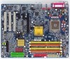
GA-8I915P Duo (Pro) Motherboard Layout DDRII_2 DDRII_1 DDR1 DDR2 PWR_FAN KB_MS ATX_12V LGA775 ATX SPDIF_O SPDIF_I CPU_FAN COMA LPT IDE1 GA-8I915P Duo (Pro) USB USB LAN2 LAN1 AUDIO1 AUDIO2 CD_IN AZALIA_FP Broadcom 5751 /5789 NB_FAN Broadcom 5751/5789 PCIE_1 CODEC PCIE_2 - Gigabyte GA-8I915P Duo | Manual - Page 7
Back Surround Speaker Out Center/Subwoofer Speaker Out Surround Speaker Out MIC Line-Out Line-In SPDIF In SPDIF Out (Note) To use a DDRII 600 memory module on the motherboard, you must install an 800MHz FSB processor and overclock in BIOS. Only for GA-8I915P Duo Pro. Only for GA-8I915P Duo. - 7 - - Gigabyte GA-8I915P Duo | Manual - Page 8
- 8 - - Gigabyte GA-8I915P Duo | Manual - Page 9
instructions below: 1. Please turn off the computer and unplug its power cord. 2. When handling the motherboard motherboard. Installation Notices 1. Prior to installation, please do not remove the stickers on the motherboard the motherboard or or have a problem related to the the user manual. 3. Damage - Gigabyte GA-8I915P Duo | Manual - Page 10
Š Onboard Broadcom 5751/5789 chip (10/100/1000 Mbit) Š 2 RJ 45 port--LAN1 / LAN2 (Note) To use a DDRII 600 memory module on the motherboard, you must install an 800MHz FSB processor and overclock in BIOS. Only for GA-8I915P Duo Pro. Only for GA-8I915P Duo. GA-8I915P Duo (Pro) Motherboard - 10 - - Gigabyte GA-8I915P Duo | Manual - Page 11
Š CPU smart fan control Š Use of licensed AWARD BIOS Š Supports Dual BIOS /Q-Flash/Multilanguage Š Supports @BIOS Š Supports EasyTune Š Over Voltage via BIOS (CPU/DDR/PCI-E) Š Over Clock via BIOS (CPU/DDR) Š ATX form factor; 30.5cm x 24.4cm Only for GA-8I915P Duo Pro. - 11 - Hardware Installation - Gigabyte GA-8I915P Duo | Manual - Page 12
card, memory, hard Processor with HT Technology - Chipset: An Intel® Chipset that supports HT Technology - BIOS: A BIOS that supports socket in a straight and downwards motion. Avoid twisting or bending motions that might cause damage to the CPU during installation.) GA-8I915P Duo (Pro) Motherboard - Gigabyte GA-8I915P Duo | Manual - Page 13
make sure the Male and Female push pin are joined closely. (for detailed installation instructions, please refer to the heatsink installation section of the user manual) Fig. 5 Please check the back of motherboard after installing. If the push pin is inserted as the picture, the installation is - Gigabyte GA-8I915P Duo | Manual - Page 14
in one direction. Insert the DIMM memory module vertically into the DIMM socket. Then push it down. Fig.2 Close the plastic clip at both edges of the DIMM sockets to lock the DIMM module. Reverse the installation steps when you wish to remove the DIMM module. GA-8I915P Duo (Pro) Motherboard - 14 - - Gigabyte GA-8I915P Duo | Manual - Page 15
DDR/DDR II GA-8I915P Duo (Pro) supports the Dual Channel Technology. After operating the Dual Channel Technology, the bandwidth of Memory Bus will add double up to 6.4GB/s(DDR) ; 8.5GB(DDRII) GA-8I915P Duo (Pro) includes 4 DIMM sockets, and each Channel has two DIMM sockets as following: Channel - Gigabyte GA-8I915P Duo | Manual - Page 16
outlined below: 1. Read the related expansion card's instruction document before install the expansion card into the the computer, if necessary, setup BIOS utility of expansion card from BIOS. 8. Install related driver from the operating system. Installing a GA-8I915P Duo (Pro) Motherboard - 16 - - Gigabyte GA-8I915P Duo | Manual - Page 17
output is capable of providing digital audio to external speakers or compressed AC3 devices. LAN Port 1 The provided Internet connection supports USB controller. If your OS does not support USB controller, please contact OS ven dor for possible patch or driver GA-8I915P Duo Pro. - 17 - Hardware Installation - Gigabyte GA-8I915P Duo | Manual - Page 18
audio software to configure 2-/4-/5.1-/7.1-channel audio functioning. 1-7 Connectors Introduction 1 53 2 8 14 13 18 6 4 9 19 10 7 12 17 16 15 11 1) ATX_12V 2) ATX 16) F1_1394 / F2_1394 17) IR 18) CLR_CMOS 19) BAT Only for GA-8I915P Duo Pro. GA-8I915P Duo (Pro) Motherboard - 18 - - Gigabyte GA-8I915P Duo | Manual - Page 19
result can lead to an unstable system or a system that is unable to start. If you use a 24-pin ATX power supply, please remove the small cover on the power connector on the motherboard before plugging in the power cord ; Otherwise, please do not remove it. 13 24 Pin No. 1 2 3 4 Definition GND - Gigabyte GA-8I915P Duo | Manual - Page 20
installed wrong direction, the chip fan will not work. Sometimes will damage the chip fan. (Usually black cable is GND) Pin No. Definition 1 1 +12V 2 GND GA-8I915P Duo (Pro) Motherboard - 20 - - Gigabyte GA-8I915P Duo | Manual - Page 21
other end of the cable connects to the FDD drive. The types of FDD drives supported are: 360KB, 720KB, 1.2MB, 1.44MB and 2.88MB. Please connect the red the other as Slave (for information on settings, please refer to the instructions located on the IDE device). To ensure that an IDE CD-ROM drive - Gigabyte GA-8I915P Duo | Manual - Page 22
Connector) Serial ATA can provide 150MB/s transfer rate. Please refer to the BIOS setting for the Serial ATA and install the proper driver in order to work properly. Pin No. Definition 1 GND 7 1 2 mode. Pin No. Definition 1 1 MPD+ 2 MPD- 3 MPD- GA-8I915P Duo (Pro) Motherboard - 22 - - Gigabyte GA-8I915P Duo | Manual - Page 23
English 12) F_PANEL (Front Panel Jumper) Please connect the power LED, PC peaker, reset switch and power switch etc of your chassis front panel to the F_PANEL connector according to the pin assignment below. Message LED/ Power/ Sleep LED Speaker Connector Power Switch MSG+ MSG- PW+ PWSPEAK+ - Gigabyte GA-8I915P Duo | Manual - Page 24
setting for this connector. To enable AC'97 Audio, from BIOS settings, set Front Panel Type under Integrated Peripherals to AC97. 14) CD_IN (CD IN) Connect CD-ROM or DVD-ROM audio out to the connector. Pin No. Definition 1 1 CD-L 2 GND 3 GND 4 CD-R GA-8I915P Duo (Pro) Motherboard - 24 - - Gigabyte GA-8I915P Duo | Manual - Page 25
USB cable, please contact your local dealer. The "USB Device Wake up From S3" is only supported by rear USB ports. 2 10 1 9 Pin No. 1 2 3 4 5 6 7 Power 2 10 3 TPA0+ 4 TPA0- 1 9 F1_1394 5 GND 6 GND Only for GA-8I915P Duo Pro. Pin No. 1 2 3 4 5 6 7 8 9 10 Definition TPA2+ TPA2GND - Gigabyte GA-8I915P Duo | Manual - Page 26
this jumper. To clear CMOS, temporarily short 1-2 pin. Default doesn't include the "Shunter" to prevent from improper use this jumper. 1 Open: Normal 1 Short: Clear CMOS GA-8I915P Duo (Pro) Motherboard - 26 - - Gigabyte GA-8I915P Duo | Manual - Page 27
is incorrectly replaced. Replace only with the same or equivalent type recommended by the manufacturer. Dispose of used batteries according to the manufacturer's instructions. If you want to erase CMOS... 1.Turn OFF the computer and unplug the power cord. 2.Remove the battery, wait for 30 second - Gigabyte GA-8I915P Duo | Manual - Page 28
English GA-8I915P Duo (Pro) Motherboard - 28 - - Gigabyte GA-8I915P Duo | Manual - Page 29
at the bottom of the screen. Status Page Setup Menu / Option Page Setup Menu Press F1 to pop up a small help window that describes the appropriate keys to use and the possible selections for the highlighted item. To exit the Help Window press . Only for GA-8I915P Duo Pro. - 29 - BIOS Setup - Gigabyte GA-8I915P Duo | Manual - Page 30
PCI Configurations ` PC Health Status ` MB Intelligent Tweaker(M.I.T.) ESC: Quit F8: Dual BIOS 1/Q-Flash Select Language 1 Load Fail-Safe Defaults Load Optimized Defaults Set Supervisor the system would be in safe configuration. Only for GA-8I915P Duo Pro. GA-8I915P Duo (Pro) Motherboard - 30 - - Gigabyte GA-8I915P Duo | Manual - Page 31
system. „ Save & Exit Setup Save CMOS value settings to CMOS and exit setup. „ Exit Without Saving Abandon all CMOS value changes and exit setup. - 31 - BIOS Setup - Gigabyte GA-8I915P Duo | Manual - Page 32
F6: Fail-Safe Default ESC: Exit F1: General Help F7: Optimized Defaults Date The date format is , , , . Week The week, from Sun to Sat, determined by the BIOS start up. Manual User can manually input the GA-8I915P Duo Pro. GA-8I915P Duo (Pro) Motherboard - 32 - - Gigabyte GA-8I915P Duo | Manual - Page 33
88M byte capacity. Floppy 3 Mode Support (for Japan Area) Disabled Normal memory is typically 512K for systems with 512K memory installed on the motherboard, or 640K for systems with 640K or more memory installed on the motherboard. Extended Memory The BIOS determines how much extended memory - Gigabyte GA-8I915P Duo | Manual - Page 34
your boot device priority by USB-HDD. LAN Select your boot device priority by LAN. Disabled Select your boot device priority by Disabled. Only for GA-8I915P Duo Pro. (Note) This item will show up when you install a processor which supports this function. GA-8I915P Duo (Pro) Motherboard - 34 - - Gigabyte GA-8I915P Duo | Manual - Page 35
system with multi processors mode supported. (Default value) Disabled Disables CPU Hyper Threading. Limit CPUID Max. to 3 Enabled Limit CPUID Maximum value to 3 when use older OS like NT4. Disabled Disables CPUID Limit for windows XP. (Default value) No-Execute Memory Protect (Note) Enabled - Gigabyte GA-8I915P Duo | Manual - Page 36
[Disabled] [Disabled] [Auto] [HD Audio] [Enabled] [Enabled] [Enabled] [ F3: Language 1 F5: Previous Values F6: Fail-Safe Default ESC: Exit F1 Support hotplug function under OS. WinXP,2000 only. Select onboard Seria ATA function as ATA. Only for GA-8I915P Duo Pro. GA-8I915P Duo (Pro) Motherboard - Gigabyte GA-8I915P Duo | Manual - Page 37
Audio Panel to the AZALIA_FP connector, set this item to HD Audio. If you connect AC97 Audio Panel to the AZALIA_FP connector, set this item to AC97. AC97 HD Audio Set front audio panel type to AC97. Set front audio panel type to HD Audio. (Default value) Only for GA-8I915P Duo Pro. - 37 - BIOS - Gigabyte GA-8I915P Duo | Manual - Page 38
and address is 2E8. Disabled Disable onboard Serial port 1. Onboard IrDA Port Auto 3F8/IRQ4 BIOS will automatically setup the port 1 address. Enable onboard IrDA port and address is 3F8. chip UART to IrDA Mode. (Default value) Only for GA-8I915P Duo Pro. GA-8I915P Duo (Pro) Motherboard - 38 - - Gigabyte GA-8I915P Duo | Manual - Page 39
Parallel port as ECP & EPP mode. ECP Mode Use DMA 3 Set ECP Mode Use DMA to 3. (Default value) 1 Set ECP Mode Use DMA to 1. - 39 - BIOS Setup - Gigabyte GA-8I915P Duo | Manual - Page 40
Level` KLJI: Move Enter: Select +/-/PU/PD: Value F10: Save F3: Language 1 F5: Previous Values F6: Fail-Safe Default ESC: Exit F1: General Help F7: Optimized Defaults ACPI Suspend Type S1(POS) S3( to power on the system. Only for GA-8I915P Duo Pro. GA-8I915P Duo (Pro) Motherboard - 40 - - Gigabyte GA-8I915P Duo | Manual - Page 41
system, the system will be in "Off" state. (Default value) Full-On When AC-power back to the system, the system always in "On" state. Memory When AC-power back to the system, the system will return to the Last state before AC-power off. - 41 - Gigabyte GA-8I915P Duo | Manual - Page 42
KLJI: Move Enter: Select +/-/PU/PD: Value F10: Save F3: Language 1 F5: Previous Values F6: Fail-Safe Default ESC: Exit F1: General Help F7: Optimized Defaults PCI 1 IRQ Assignment Auto 3,4,5,7,9,10 10,11,12,14,15 to PCI 3. Only for GA-8I915P Duo Pro. GA-8I915P Duo (Pro) Motherboard - 42 - - Gigabyte GA-8I915P Duo | Manual - Page 43
Level` KLJI: Move Enter: Select +/-/PU/PD: Value F10: Save F3: Language 1 F5: Previous Values F6: Fail-Safe Default ESC: Exit F1: General Help F7: Optimized Defaults Current Voltage(V) Vcore / DDRV / degrees Celsius, CPU fan will be disable. Only for GA-8I915P Duo Pro. - 43 - BIOS Setup - Gigabyte GA-8I915P Duo | Manual - Page 44
Control is enabled. Auto BIOS autodetects the type of PCI-E Frequency to CPU Memory Frequency For Memory Frequency (Mhz) DIMM OverVoltage F10: Save F3: Language 1 F5: Previous Values F6: Fail-Safe Default ESC: Exit F1: General Help GA-8I915P Duo Pro. GA-8I915P Duo (Pro) Motherboard - 44 - - Gigabyte GA-8I915P Duo | Manual - Page 45
OverVoltage Control to Normal. (Default value) +0.1V Set DIMM OverVoltage Control to +0.1V. +0.2V Set DIMM OverVoltage Control to +0.2V. (Note) To use a DDRII 600 memory module on the motherboard, you must install an 800MHz FSB processor and set Memory Frequency For to 3.00. - 45 - BIOS Setup - Gigabyte GA-8I915P Duo | Manual - Page 46
Control Supports adjustable Dual BIOS 1/Q-Flash F3: Change Language 1 F10: Save & Exit Setup Load Fail-Safe Defaults Fail-Safe defaults contain the most appropriate values of the system parameters that allow minimum system performance. Only for GA-8I915P Duo Pro. GA-8I915P Duo (Pro) Motherboard - Gigabyte GA-8I915P Duo | Manual - Page 47
User Password Save & Exit Setup Exit Without Saving ESC: Quit F8: Dual BIOS 1/Q-Flash F3: Change Language 1 F10: Save & Exit Setup Change/Set at "Password Check" in Advance BIOS Features Menu, you will be prompted only when you try to enter Setup. Only for GA-8I915P Duo Pro. - 47 - BIOS Setup - Gigabyte GA-8I915P Duo | Manual - Page 48
and EXISTa(vYe/&N)E?xYit Setup ` MB Intelligent Tweaker(M.I.T.) Exit Without Saving ESC: Quit F8: Dual BIOS 1/Q-Flash F3: Change Language 1 F10: Save & Exit Setup Save & Exit Setup Type Type "N" will return to Setup Utility. Only for GA-8I915P Duo Pro. GA-8I915P Duo (Pro) Motherboard - 48 - - Gigabyte GA-8I915P Duo | Manual - Page 49
will continue to install other drivers. System will reboot automatically after install the drivers, afterward you can install others application. For USB2.0 driver support under Windows XP operating system, please use Windows Service Pack. After install Windows Service Pack, it will show a question - Gigabyte GA-8I915P Duo | Manual - Page 50
Applications This page displays all the tools that Gigabyte developed and some free software, you can choose anyone you want and press "install" to install them. 3-3 Driver CD Information This page lists the contents of software and drivers in this CD-title. GA-8I915P Duo (Pro) Motherboard - 50 - - Gigabyte GA-8I915P Duo | Manual - Page 51
English 3-4 Hardware Information This page lists all device you have for this motherboard. 3-5 Contact Us Please see the last page for details. - 51 - Install Drivers - Gigabyte GA-8I915P Duo | Manual - Page 52
English GA-8I915P Duo (Pro) Motherboard - 52 - - Gigabyte GA-8I915P Duo | Manual - Page 53
factory defaults to provide a more user-friendly and reliable platform for users. Download Center Download Center allows users to quickly download and update their BIOS as well as the latest drivers for their system. Download Center automatically runs a system check of the user PC and provides the - Gigabyte GA-8I915P Duo | Manual - Page 54
. . . Verifying DMI Pool Data Boot from CD: Boot from CD: Xpress Recovery V1.0 (C) Copy Right 2003. GIGABYTE Technology CO. , Ltd. 1. Execute Backup Utility 2. Execute Restore Utility 3. Remove Backup Image 4. Set Password 5. Exit and Restart Build 2011 GA-8I915P Duo (Pro) Motherboard - 54 - - Gigabyte GA-8I915P Duo | Manual - Page 55
Energy Star Al ly Copyright (C) 1984-2004, Award Software, Inc. Intel 865PE AGPSet BIOS for 8IPE1000MT F1 Check System Health OK . . . Press DEL to enter SETUP / Q-Flash, F9 For Xpress Recovery 08/16/2002-I845GE-6A69YG01C-00 F9 For Xpress Recovery Xpress Recovery V1.0 (C) Copy Right 2003. GIGABYTE - Gigabyte GA-8I915P Duo | Manual - Page 56
your system and back up data as a backup image in your hard drive. Not all systems support access to Xpress Recovery by pressing the F9 key during computer power on. If this is the password requirement. 5. Exit and Restart: Exit and restart your computer. GA-8I915P Duo (Pro) Motherboard - 56 - - Gigabyte GA-8I915P Duo | Manual - Page 57
Backup Load Default Settings Save Settings to CMOS Q-Flash Utility Update Main BIOS from Floppy Update Backup BIOS from Floppy Save Main BIOS to Floppy Save Backup BIOS to Floppy PgDn/PgUp: Modify hi: Move ESC: Reset 512K 512K F10: Power Off Only for GA-8I915P Duo Pro. - 57 - Appendix - Gigabyte GA-8I915P Duo | Manual - Page 58
Backup BIOS works normally and could automatically recover the Main BIOS. (This auto recovery utility is set by system automatically and can't be changed by user.) Load Default Settings Load dual BIOS default value. Save Settings to CMOS Save revised setting. GA-8I915P Duo (Pro) Motherboard - 58 - Gigabyte GA-8I915P Duo | Manual - Page 59
refer to Part Two. Part One: Updating BIOS with Q-FlashTM Utility on Dual BIOS Motherboards. Some of Gigabyte motherboards are equipped with dual BIOS. In the BIOS menu of the motherboards supporting Q-Flash and Dual BIOS, the Q-Flash utility and Dual BIOS utility are combined in the same screen - Gigabyte GA-8I915P Duo | Manual - Page 60
Set User Password Save & Exit Setup Exit Without Saving ESC: Quit F8: Dual BIOS/Q-Flash F3: Change Language F10: Save & Exit Setup Time, Date, Hard the Q-Flash/Dual BIOS utility. Pressing the buttons mentioned on your keyboards to perform these actions. GA-8I915P Duo (Pro) Motherboard - 60 - - Gigabyte GA-8I915P Duo | Manual - Page 61
download one BIOS file to the floppy disk so only one BIOS file, 8KNXPU.Fba, is listed. Please confirm again you have the correct BIOS file for your motherboard. Dual BIOS Utility Boot From Main Bios progress of reading the BIOS file from the floppy disk. Dual BIOS Utility Boot From Main Bios - Gigabyte GA-8I915P Duo | Manual - Page 62
Channel Primary Master : FUJITSU MPE3170AT ED-03-08 Primary Slave : None Secondary Master : CREATIVEDVD-RM DVD1242E BC101 Secondary Slave : None Press DEL to enter SETUP / Dual BIOS / Q-Flash / F9 For Xpress Recovery 09/23/2003-i875P-6A79BG03C-00 GA-8I915P Duo (Pro) Motherboard - 62 - - Gigabyte GA-8I915P Duo | Manual - Page 63
Quit F8: Dual BIOS/Q-Flash F3: Change Language F10: Save & Exit Setup Time, Date, Hard Disk Type... Press Y on your keyboard to save and exit. Part Two: Updating BIOS with Q-FlashTM Utility on Single-BIOS Motherboards. This part guides users of single-BIOS motherboards how to update BIOS using the - Gigabyte GA-8I915P Duo | Manual - Page 64
:tRemeset F10:Power Off Do not trun off power or reset your system at this stage!! After BIOS file is read, you'll see a confirmation dialog box asking you "Are you sure to update BIOS?" Please do not take out the floppy disk when it begins flashing BIOS. GA-8I915P Duo (Pro) Motherboard - 64 - - Gigabyte GA-8I915P Duo | Manual - Page 65
file becomes F4 after updating Award Modular BIOS v6.00PG, An Energy Star Ally Copyright (C) 1984-2003, Award Software, Inc. Intel 845GE AGPSet BIOS for 8GE800 F4 Check System Health OK Main Processor : Intel Pentium(R) 4 1.7GHz (100x17.0) Memory Testing : 122880K OK - Gigabyte GA-8I915P Duo | Manual - Page 66
"Update New BIOS" c. Please select "All Files" in dialog box while opening the old file. d. Please search for BIOS unzip file, downloading from internet or any other methods (such as: 8I915P Duo Pro.F1). e. Complete update process following the instruction. GA-8I915P Duo (Pro) Motherboard - 66 - Gigabyte GA-8I915P Duo | Manual - Page 67
II, be sure that motherboard's model name in BIOS unzip file are the same as your motherboard's. Otherwise, your system won't boot. III. In method I, if the BIOS file you need cannot be found in @BIOSTM server, please go onto Gigabyte's web site for downloading and updating it according to method - Gigabyte GA-8I915P Duo | Manual - Page 68
4-1-3 Serial ATA BIOS Setting Utility Introduction RAID . The striping block size can be set from 4KB to 64KB. RAID 0 does not support fault tolerance. RAID 1 (Mirroring) RAID 1 writes duplicate data onto a pair of drives array. Only for GA-8I915P Duo Pro. GA-8I915P Duo (Pro) Motherboard - 68 - - Gigabyte GA-8I915P Duo | Manual - Page 69
motherboard BIOS and locate RAID setup (Please refer to the section on Integrated Peripherals). 4) Enter RAID setup in the BIOS and select the RAID type (For instance, enter Ctrl + I to select Intel RAID; Ctrl + S to select Silicon Image). 5) Complete driver I before the window disappears. Intel(R) - Gigabyte GA-8I915P Duo | Manual - Page 70
]-Previous Menu [ENTER]-Select There are two RAID levels: RAID0(Stripe) and RAID1(Mirror). After selecting the RAID level, press Enter to select Strip Size. GA-8I915P Duo (Pro) Motherboard - 70 - - Gigabyte GA-8I915P Duo | Manual - Page 71
English The KB is a unit of Strip Size. You can set disk block size with this item. The disk block size can be set from 4KB to 128KB. After you set disk block size, press Enter to set disk Capacity. Intel(R) Application Accelerator RAID Option ROM v4.0.6180 Copyright(C) 2003-04 Intel Corporation. - Gigabyte GA-8I915P Duo | Manual - Page 72
. Are you sure you want to creat this volume? (Y/N) : Press "ENTER" to Create the specified volume [hi]-Change [TAB]-Next [ESC]-Previous Menu [ENTER]-Select GA-8I915P Duo (Pro) Motherboard - 72 - - Gigabyte GA-8I915P Duo | Manual - Page 73
Status 223.5GB Normal Bootable Yes Physical Disks : Port Driver Model 0 ST3120026AS 1 ST3120026AS Serial # 3JT354CP 3JT329JX Size select the Delete RAID Volume option. Press Enter key and follow the instructions on the screen. Intel(R) Application Accelerator RAID Option ROM v4.0.6180 - Gigabyte GA-8I915P Duo | Manual - Page 74
add a new hard drive to a RAID array, the RAID driver will have to be installed under Windows once for that hard drive. After that, the driver will not have to be installed.) Note: In the menu list, Intel Application Accelerator 4.0 is Intel ICH6R chipset. GA-8I915P Duo (Pro) Motherboard - 74 - - Gigabyte GA-8I915P Duo | Manual - Page 75
After installation of the audio driver, you'll find an icon in the system area. Double click the icon to select the function. If the icon can not be found, go to the control panel from the system menu and double click the C-Media CPL icon. Open "CMI Audio Config" and then go - Gigabyte GA-8I915P Duo | Manual - Page 76
the audio driver, you'll find an audio mode is displayed in "Audio System Status". "Smart Jack" would auto-detect the speaker type you connect and gives you the functions to manually modify the speaker settings. The function to manually modify speaker settings. GA-8I915P Duo (Pro) Motherboard - Gigabyte GA-8I915P Duo | Manual - Page 77
speaker out". STEP 2: After installation of the audio driver, you'll find an icon in the system audio mode is display in "Audio System Status". "Smart Jack" would auto-detect the speaker type you connect and gives you the functions to manually modify speaker the settings. The function to manually - Gigabyte GA-8I915P Duo | Manual - Page 78
audio mode is display in "Audio System Status". "Smart Jack" would auto-detect the speaker type you connect and gives you the functions to manually modify speaker the settings. The function to manually modify speaker setting. The function to adjust speaker volume. GA-8I915P Duo (Pro) Motherboard - Gigabyte GA-8I915P Duo | Manual - Page 79
speaker out". STEP 2: After installation of the audio driver, you find an icon in the system area. audio mode is display in "Audio System Status". "Smart Jack" would auto-detect the speaker type you connect and gives you the functions to manually modify speaker the settings. The function to manually - Gigabyte GA-8I915P Duo | Manual - Page 80
Multiple Streaming" and restart the system to enable support for multiple audio output function. Defaults: The defaults for both "Sound the multiple audio output function. Note:The function can be used only when you connect the audio device to front panel. GA-8I915P Duo (Pro) Motherboard - 80 - Gigabyte GA-8I915P Duo | Manual - Page 81
Troubleshooting Below is a collection of general asked questions. To check general asked questions based on a specific motherboard model, please log on to http://tw.giga-byte.com/faq/faq.htm Question 1: I cannot see some options that were included in previous BIOS after updating BIOS the manual. If - Gigabyte GA-8I915P Duo | Manual - Page 82
memory failure 4 beeps Timer not operational 5 beeps Processor error 6 beeps 8042 - gate A20 failure 7 beeps Processor exception interrupt error 8 beeps Display memory short: BIOS ROM error Continuous long beeps: DRAM error Continuous short beeps: Power error GA-8I915P Duo (Pro) Motherboard - - Gigabyte GA-8I915P Duo | Manual - Page 83
- 83 - Appendix English - Gigabyte GA-8I915P Duo | Manual - Page 84
English GA-8I915P Duo (Pro) Motherboard - 84 - - Gigabyte GA-8I915P Duo | Manual - Page 85
- 85 - Appendix English - Gigabyte GA-8I915P Duo | Manual - Page 86
English GA-8I915P Duo (Pro) Motherboard - 86 - - Gigabyte GA-8I915P Duo | Manual - Page 87
Bletchley Milton Keynes, MK1 1DR, UK, England TEL: +44-1908-362700 FAX: +44-1908-362709 Tech. Support : http://uk.giga-byte.com/TechSupport/ServiceCenter.htm Non-Tech. Support(Sales/Marketing) : http://ggts.gigabyte.com.tw/nontech.asp WEB address : http://uk.giga-byte.com - The Netherlands GIGA-BYTE - Gigabyte GA-8I915P Duo | Manual - Page 88
gigabyte.ru - Poland Representative Office Of Giga-Byte Technology Co., Ltd. POLAND Tech. Support : http://tw.giga-byte.com/TechSupport/ServiceCenter.htm Non-Tech. Support(Sales/Marketing) : http://ggts.gigabyte.com.tw/nontech.asp WEB address : http://www.gigabyte.pl GA-8I915P Duo (Pro) Motherboard
-
 1
1 -
 2
2 -
 3
3 -
 4
4 -
 5
5 -
 6
6 -
 7
7 -
8
-
9
-
10
-
11
-
12
-
13
-
14
-
15
-
16
-
17
-
18
-
19
-
20
-
21
-
22
-
23
-
24
-
25
-
26
-
27
-
28
-
29
-
30
-
31
-
32
-
33
-
34
-
35
-
36
-
37
-
38
-
39
-
40
-
41
-
42
-
43
-
44
-
45
-
46
-
47
-
48
-
49
-
50
-
51
-
52
-
53
-
54
-
55
-
56
-
57
-
58
-
59
-
60
-
61
-
62
-
63
-
64
-
65
-
66
-
67
-
68
-
69
-
70
-
71
-
72
-
73
-
74
-
75
-
76
-
77
-
78
-
79
-
80
-
81
-
82
-
83
-
84
-
85
-
86
-
87
-
88
 |
 |

GA-8I915P Duo (Pro)
Intel
®
Pentium
®
4 LGA775 Processor Motherboard
User's Manual
Rev. 1303
12ME-8I915PUP-1303