Gigabyte GA-8I915P-G Manual
Gigabyte GA-8I915P-G Manual
 |
View all Gigabyte GA-8I915P-G manuals
Add to My Manuals
Save this manual to your list of manuals |
Gigabyte GA-8I915P-G manual content summary:
- Gigabyte GA-8I915P-G | Manual - Page 1
GA-8I915P Series Intel® Pentium® 4 LGA775 Processor Motherboard User's Manual Rev. 2002 12ME-8I915PU-2002 - Gigabyte GA-8I915P-G | Manual - Page 2
Motherboard GA-8I915P/GA-8I915P Ultra/GA-8I915P Pro/GA-8I915P-G Aug.17, 2004 Motherboard GA-8I915P/GA-8I915P Ultra/ GA-8I915P Pro/GA-8I915P-G Aug. 17, 2004 - Gigabyte GA-8I915P-G | Manual - Page 3
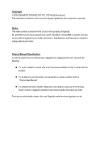
Classification In order to assist in the use of this product, Gigabyte has categorized the user manual in the following: n For quick installation, please refer to the "Hardware Installation Guide" included with the product. n For detailed productinformation and specifications, please carefully - Gigabyte GA-8I915P-G | Manual - Page 4
Table of Contents GA-8I915P (Ultra)(Pro)(-G) Motherboard Layout 6 Block Diagram ...7 Chapter 1 Hardware Installation 9 1-1 Considerations Priorto Installation 9 1-2 Feature Summary 10 1-3 Installation of the CPU and Heatsink 12 1-3-1 Installation of the CPU 12 1-3-2 Installation of the - Gigabyte GA-8I915P-G | Manual - Page 5
Chapter 3 Install Drivers 49 3-1 Install Chipset Drivers 49 3-2 SoftwareApplications 50 3-3 Driver CD Information 50 3-4 Hardware Information 51 3-5 Contact Us ...51 Chapter 4 Appendix 53 4-1 Unique Software Utilities 53 4-1-1 Xpress Recovery Introduction 54 4-1-2 Flash BIOS Method - Gigabyte GA-8I915P-G | Manual - Page 6
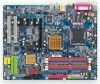
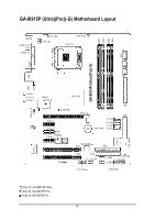
Motherboard Layout KB_MS SP DIF_O UT SP DIF_IN C PU _ FAN A TX_12V PWR_FA N LGA 775 GA-8I915P (Ultra)(Pro)(-G) DDR1 DDR2 DDR3 DDR4 ATX LPT COMA USB LAN USB IT8212 CLR_CMOS A U D IO 1 A U D IO 2 Marv ell 8001 I ntel 915P AZALIA_FP CD_IN C ODEC N B_ FAN P CI E_1 P CI E_2 BAC K BIOS - Gigabyte GA-8I915P-G | Manual - Page 7
8 USB Ports PS/2 KB/M ouse 24MHz 33MHz 2 PCI PCICLK (33M Hz) IT8 212 IDE RAID IDE2/IDE3 3 IEEE1394 Back Surround Speaker Out Center/Subwoofer Speaker Out Surround Speaker Out MIC Line-Out Line-In SPDIF In SPDIF Out Only for GA-8I915P Ultra. Only for GA-8I915P Pro. Only for GA-8I915P-G. - 7 - - Gigabyte GA-8I915P-G | Manual - Page 8
- 8 - - Gigabyte GA-8I915P-G | Manual - Page 9
the instructions below: 1. Please turn off the computer and unplug its power cord. 2. When handling the motherboard, avoid touching any metal leads or connectors. 3. It is best to wear an electrostatic discharge (ESD) cuff when handling electronic components (CPU, RAM). 4. Prior to installing the - Gigabyte GA-8I915P-G | Manual - Page 10
LAN Onboard Audio w Supports the latest Intel® Pentium® 4 LGA775 CPU w Supports 800/533MHz FSB w L2 cache varies with CPU w GA-8I915P Series Motherboard: GA-8I915P Ultra/GA-8I915P Pro/GA-8I915P-G/GA-8I915P w Northbridge: Intel® 915P Express Chipset w Southbridge: Intel® ICH6 w 4 DDR DIMM memory - Gigabyte GA-8I915P-G | Manual - Page 11
AWARD BIOS w Supports Dual BIOS /Q-Flash Additional Features w Supports @BIOS w Supports EasyTune O ve rc lo ck in g w Over Voltage via BIOS (CPU/DDR/PCI-E) w Over Clock via BIOS (CPU/DDR) Form Factor w ATX form factor; 30.5cm x 24.4cm Only for GA-8I915P Ultra. Only for GA-8I915P Pro. - 11 - Gigabyte GA-8I915P-G | Manual - Page 12
in a straight and downwards motion. Avoid twisting or bending motions that m ight cause dam age to the CPU during installation.) GA-8I915P Series Motherboard - 12 - Fig. 4 Once the CPU is properly inserted, please replace the plastic covering and push the m etal lever back into its original - Gigabyte GA-8I915P-G | Manual - Page 13
sta ll .) Please note the direction of arrow sign on the m ale push pin doesn't face inwards before installation. (This instruction is only for Intel boxed fan) Fig. 3 Place the heatsink atop the CPU and m ake sure the push pins aim to the pin hole on the m otherboard.Pressing down the push pins - Gigabyte GA-8I915P-G | Manual - Page 14
supports DDR memory modules, whereby BIOS memory module vertically into the DIMM socket. Then push it down. Fig.2 Close the plastic clip at both edges of the DIMM sockets to lock the DIMM module. Reverse the installation steps when you wish to remove the DIMM m odule. GA-8I915P Series Motherboard - Gigabyte GA-8I915P-G | Manual - Page 15
English Dual Channel DDR GA-8I915P Series supports the Dual Channel Technology. After operating the Dual Channel Technology, the bandwidth of Mem ory Bus will add double up to 6.4GB/s. GA-8I915P Series includes 4 DIMM sockets, and each Channel has two DIM M sockets as following: Channel A : DDR 1, - Gigabyte GA-8I915P-G | Manual - Page 16
end of the PCI Express x 16 slot when you try to install/Uninstall the VGA card. Please align the VGA card to the onboard PCI Express x 16 slot and press firmly down on the slot .M ake sure your VGA card is locked by the sm all white-drawable bar. GA-8I915P Series Motherboard - 16 - - Gigabyte GA-8I915P-G | Manual - Page 17
audio supports USB controller. If your OS does not support USB controller, please contact OS vendor for possible patch or driver upgrade. For more information please contact your OS or device(s) vendors. LAN GA-8I915P Ultra. Only for GA-8I915P Pro. Only for GA-8I915P-G. - 17 - Hardware Installation - Gigabyte GA-8I915P-G | Manual - Page 18
the surround channels to this connector. You can use audio software to configure 2-/4-/5.1-/7.1-channel audio functioning. 1-7 Connectors Introduction 13 5 2 6 8 F2_1394 17) I R 18) CLR_CMOS 19) BAT Only for GA-8I915P Ultra. Only for GA-8I915P Pro. GA-8I915P Series Motherboard - 18 - - Gigabyte GA-8I915P-G | Manual - Page 19
connector, please make sure that all components and devices are properly installed. Align the power connector with its proper location on the motherboard and connect tightly. The ATX_12V power connector mainly supplies power to the CPU. If the ATX_12V power connector is not connected, the system - Gigabyte GA-8I915P-G | Manual - Page 20
! Please remember to connect the power to the CPU fan to prevent CPU overheating and failure. 1 C PU_ F AN installed wrong direction, the chip fan will not work. Sometimes will damage the chip fan. (Usually black cable is GND) Pin No. Definition 1 1 +12V 2 GND GA-8I915P Series Motherboard - Gigabyte GA-8I915P-G | Manual - Page 21
cable while the other end of the cable connects to the FDD drive. The types of FDD drives supported are:360KB, 720KB, 1.2MB, 1.44MB and 2.88MB. Please connect the red power connector wire to , please refer to the instructions located on the IDE device). 1 2 2 40 1 39 40 - 21 - 39 Hardware - Gigabyte GA-8I915P-G | Manual - Page 22
) Serial ATA can provide 150M B/s transfer r ate. Please refer to the BIOS setting for the Serial ATA and install the proper driver in order to work properly. Pin No. Definition 7 1 1 GND 2 TXP mode. Pin No. Definition 1 MPD+ 1 2 MPD- 3 MPD- GA-8I915P Series Motherboard - 22 - - Gigabyte GA-8I915P-G | Manual - Page 23
Pin 4: Data(-) Open:Normal Operation Close: Reset Hardware System Open:Normal Operation Close:Power On/Off Pin 1: LED anode(+) Pin 2: LED cathode(-) NC - 23 - Hardware Installation - Gigabyte GA-8I915P-G | Manual - Page 24
ent on the M B header. To find out ifthe chassis you are buying support front audio panel connector, please contact your dealer. 10 9 2 1 Pin No. 1 CD-ROM or DVD-ROM audio out to the connector. Pin No. Definition 1 CD-L 2 GND 1 3 GND 4 CD-R GA-8I915P Series Motherboard - 24 - - Gigabyte GA-8I915P-G | Manual - Page 25
cable, please contact your local dealer. The "USB Device Wake up From S3" is only supported by rear USB ports. 2 10 1 9 Pin No. 1 2 3 4 5 6 IEEE1394 cable, please contact your local dealer. 2 16 Only for GA-8I915P Ultra. Only for GA-8I915P Pro. 1 F2_1394 1 5 2 10 1 9 F1_1394 Pin No. - Gigabyte GA-8I915P-G | Manual - Page 26
this jumper. To clear CMOS, temporarily short 1-2 pin. Default doesn't include the "Shunter" to prevent from improper use this jumper. 1 Open:Normal 1 Short:Clear CMOS GA-8I915P Series Motherboard - 26 - - Gigabyte GA-8I915P-G | Manual - Page 27
if batteryis incorrectly replaced. Replace only with the same or equivalent type recommended bythe manufacturer. Dispose of used batteries according to the manufacturer's instructions. If you want to erase CM OS... 1.Turn OFF the computer and unplug the power cord. 2.Remove the battery, wait for 30 - Gigabyte GA-8I915P-G | Manual - Page 28
English GA-8I915P Series Motherboard - 28 - - Gigabyte GA-8I915P-G | Manual - Page 29
Page Setup Menu Load the file-safe default CMOS v alue from BIOS default table Load the Optimized Defaults Dual BIOS /Q-F lash utility Sy stem Information Sav e allthe CMOS changes, only . To ex it the Help Window press . Only for GA-8I915P Ultra. Only for GA-8I915P Pro. - 29 - BIOS Setup - Gigabyte GA-8I915P-G | Manual - Page 30
Dual ed Defaults in the BIOS w hen somehow CPU clock and frequency ratio. n Load Fail -Safe Defaults Fail-Safe Defaults indicates the v alue of the sy stem parameters w hich the sy stem w ould be in safe configu ration. Only for GA-8I915P Ultra. Only for GA-8I915P Pro. GA-8I915P Series Motherboard - Gigabyte GA-8I915P-G | Manual - Page 31
n Load O ptimized Defaults Optimized Defaults indicates the v alue of the sy stem parameters w hich performancec onfiguration. n Set Supervisor Password Change, set, or disable passw ord. It allows y ou to limitaccess to the sy n Set User Password Change, set, or disable passw ord. It allow s y ou - Gigabyte GA-8I915P-G | Manual - Page 32
Week Month The w eek, from Sun toSat, determined by the BIOS and is display only The month, Jan. Through Dec. Day The day , from 1 to 31(or the max imum allow ed in the month) Ye ar The y ear a hard disk has not been installed, select NONEand press . GA-8I915P Series Motherboard - 32 - - Gigabyte GA-8I915P-G | Manual - Page 33
w ith 512K memory installed on the motherboard, or 640K for sy stems w ith 640K or more memory installed on themotherboard. Extended Memory The BIOS determines how much ex tended memory is present during the POST. This is the am ount of memory located abov e 1 MB in the CPU 's memory address map - Gigabyte GA-8I915P-G | Manual - Page 34
Check # CPU H y per-Thre ading [CDROM] [Se t up] [Enab led] Select Hard Disk Boot DevicePriority Limit CPUID Max. to install the Intel® Pentium® 4 processor w ithHT Technology. Hard Disk Boot Priority Select boot sequence for onboard(or add-on cards) SCSI, RAID GA-8I915P Series Motherboard - 34 - - Gigabyte GA-8I915P-G | Manual - Page 35
that this feature is only working for operating sy stem w ith multi processors mode supported. (Default v alue) Disabled Disables CPU Hy per Threading. Limit CPUID Max. to 3 Enab led Disabled Limit CPUID Max imum v alue to 3 w hen use older OS like NT4. (Default v alue) Disables CPUID Limit - Gigabyte GA-8I915P-G | Manual - Page 36
394 jk Onboa rd H/W Gig aRAID GigaRAID Func tion Onboa rd H/W L AN jkl Onbo ard LAN Boot ROM jkl Onboar d Serial P ort 1 Onboa rd IrDA Port UART Mode Se lect UR2 Duplex 1st channel IDE port. Only for GA-8I915P Ultra. Only for GA-8I915P Pro. Only for GA-8I915P-G. GA-8I915P Series Motherboard - 36 - - Gigabyte GA-8I915P-G | Manual - Page 37
Azalia Codec Au to Auto detect Azalia audio function. (Default v alue) Disabled Disable Azalia audio function. Onboard H/W 1394 Enab led Disabled Enable onboard IEEE 1394 function.(Default v alue) Disable thi s function. Only for GA-8I915P Ultra. Only for GA-8I915P Pro. - 37 - BIOS Setup - Gigabyte GA-8I915P-G | Manual - Page 38
of the onboard LAN chip. Enab led Enable this func tion. Disa bled Disable this function. (Default v alue) Onboard Serial P ort 1 Auto 3F8/ IRQ4 BIOS w ill IR F unction Duplex F ull. Only for GA-8I915P Ultra. Only for GA-8I915P Pro. Only for GA-8I915P-G. GA-8I915P Series Motherboard - 38 - - Gigabyte GA-8I915P-G | Manual - Page 39
Parallel port as ECP & EPP mode. ECP Mode Use DMA 3 Set ECP Mode Use DMA to 3. (Default v alue) 1 Set ECP Mode Use DMA to 1. - 39 - BIOS Setup - Gigabyte GA-8I915P-G | Manual - Page 40
By Mouse Disa bled Disabled this function. (Default v alue) Double Click Double click on PS/2 m ouse left button to pow er on the sy stem. GA-8I915P Series Motherboard - 40 - - Gigabyte GA-8I915P-G | Manual - Page 41
stem w ill be in "Off"state. (Default v alue) Full-On WhenAC-pow erback to the sy stem, the sy stem alw ay s in "On" state. Memory When AC-pow er back to the sy stem, the sy stem w ill return to the Last state before AC-pow er off. - 41 - Gigabyte GA-8I915P-G | Manual - Page 42
) Set IRQ 3,4,5,7,9,10,11,12,14,15 to PCI 1. Auto assign IRQ to PCI 2. (Default v alue) Set IRQ 3,4,5,7,9,10,11,12,14,15 to PCI 2. GA-8I915P Series Motherboard - 42 - - Gigabyte GA-8I915P-G | Manual - Page 43
degrees Celsius, CPU fan w ill run at full speed. b. The speed of CPU fan w ill increase linearly depand onthe temperature if the temperature is more than 41 degree and less than 65 degree. c. Whenthe CPU temperature is lower than 40 degrees Celsius, CPU fanw ill be disable. - 43 - BIOS Setup - Gigabyte GA-8I915P-G | Manual - Page 44
to Turbo. (Automatic ally inc rease CPU frequenc y (13%,15%,17%) by C PU loading. Full T hrust Set C .I.A.2 to Full Thrust. (Automatically increase CPU frequency (15%, 17%, 19%) by CPU loading. Warning: Stability is highly dependent on sy s tem components. GA-8I915P Series Motherboard - 44 - - Gigabyte GA-8I915P-G | Manual - Page 45
sy stem through the increase of theDIMM v oltage, damage to the memory may occur. Nor mal Set DIMM Ov erVoltage Control to Normal. CPU Voltage Co ntrol Supports adjustable CPU Vcore from 0.8375V to 1.6000V. (Default v alue: Normal) Normal CPU Vcore Display y our CPU Vcore Voltage. - 45 - BIOS - Gigabyte GA-8I915P-G | Manual - Page 46
it F8: Dual BIOSjk/Q-Flash higf:Selec t Item F10: Save & Exit Setup Load Optimized Defaults Selecting this field loads the factory defaults for BIOS and Chipset Features w hich the sy stem automatically detects. Only for GA-8I915P Ultra. Only for GA-8I915P Pro. GA-8I915P Series Motherboard - 46 - Gigabyte GA-8I915P-G | Manual - Page 47
Qu it F8: Dual BIOSjk/Q-Flash higf:Selec t Item F10: Save & Exit Setup Change/Set/Dis able Password Selecting this field loads the factory defaults for BIOS and Chipset Features w hich only w hen y ou try to enter Setup. Only for GA-8I915P Ultra. Only for GA-8I915P Pro. - 47 - BIOS Setup - Gigabyte GA-8I915P-G | Manual - Page 48
d EXITE(xYit/WN)i?thYout Saving } MB In telligent Tweaker(M. I.T.) ESC: Qu it F8: Dual BIOSjk/Q-Flash higf:Selec t Item F10: Save & Exit Setup Save & Exit Setup Ty pe "N" will return to Setup Utility. Only for GA-8I915P Ultra. Only for GA-8I915P Pro. GA-8I915P Series Motherboard - 48 - - Gigabyte GA-8I915P-G | Manual - Page 49
shown in Windows XP. Insert the driver CD-title that came with your motherboard into your CD-ROM drive, the driver CD-title will auto start and show the installation guide. If not, please double click the CD-ROM device icon in "My computer", and execute the Run.exe. 3-1 Install Chipset Drivers After - Gigabyte GA-8I915P-G | Manual - Page 50
Applications This page displays all the tools that Gigabyte developed and some free software, you can choose anyone you want and press "install" to install them. 3-3 Driver CD Information This page lists the contents of software and drivers in this CD-title. GA-8I915P Series Motherboard - 50 - - Gigabyte GA-8I915P-G | Manual - Page 51
English 3-4 Hardware Information This page lists all device you have for this motherboard. 3-5 Contact Us Please see the last page for details. - 51 - Install Drivers - Gigabyte GA-8I915P-G | Manual - Page 52
English GA-8I915P Series Motherboard - 52 - - Gigabyte GA-8I915P-G | Manual - Page 53
information as well as displaying a detailed list of all new drivers with the option for download. C.O.M. (Corporate Online Management) A web-based system management tool that allows system hardware information such as CPU, memory, graphics card, etc. to be monitored and controlled via the Internet - Gigabyte GA-8I915P-G | Manual - Page 54
on. . . Verifying DMI Pool Data Boot from CD: Boot from CD: Xpress Recovery V1.0 (C) Copy Right 2003. GIGABYTE Technology CO. , Ltd. 1. Execute Backup Utility 2. Execute Restore Utility 3. Remove Backup Image 4. Set Password 5. Exit and Restart Build 2011 GA-8I915P Series Motherboard - 54 - - Gigabyte GA-8I915P-G | Manual - Page 55
the F9 key. 2. System storage capacity as well as drive reading/writing speed will affect backup speed. 3. It is recommended that Xpress Recovery be immediately installed after OS and all required driver and software installations are complete. - 55 - Appendix - Gigabyte GA-8I915P-G | Manual - Page 56
your system and back up data as a backup image in your hard drive. Not all systems support access to Xpress Recovery by pressing the F9 key during computer power on. If this is the case password requirement. 5. Exit and Restart: Exit and restart your computer. GA-8I915P Series Motherboard - 56 - - Gigabyte GA-8I915P-G | Manual - Page 57
Settings Save Settings to CMOS Q-Flash Utility Update Main BIOS from Floppy Update Backup BIOS from Floppy Save Main BIOS to Floppy Save Backup BIOS to Floppy PgDn/PgUp: Modify hi: Move ESC: Reset Only for GA-8I915P Ultra. Only for GA-8I915P Pro. 512K 512K F10: Power Off - 57 - Appendix - Gigabyte GA-8I915P-G | Manual - Page 58
the Backup BIOS works normally and could automatically recover the Main BIOS. (This auto recovery utility is set by system automatically and can't be changed by user.) Load Default Settings Load dual BIOS default value. Save Settings to CMOS Save revised setting. GA-8I915P Series Motherboard - 58 - Gigabyte GA-8I915P-G | Manual - Page 59
refer to Part Two. Part One: Updating BIOS with Q-FlashTM Utility on Dual BIOS Motherboards. Some of Gigabyte motherboards are equipped with dual BIOS. In the BIOS menu of the motherboards supporting Q-Flash and Dual BIOS, the Q-Flash utility and Dual BIOS utility are combined in the same screen - Gigabyte GA-8I915P-G | Manual - Page 60
Set User Password Save & Exit Setup Exit Without Saving ESC: Quit F8: Dual BIOS/Q-Flash F3: Change Language F10: Save & Exit Setup Time, Date, Hard operate the Q-Flash/Dual BIOS utility. Pressing the buttons mentioned on your keyboards to perform these actions. GA-8I915P Series Motherboard - 60 - - Gigabyte GA-8I915P-G | Manual - Page 61
flash and press Enter. In this example, we only download one BIOS file to the floppy disk so only one BIOS file, 8KNXPU.Fba, is listed. Please confirm again you have the correct BIOS file for your motherboard. Dual BIOS Utility Boot From Main Bios Main ROM Type/Size SST 49LF004A Backup ROM Type - Gigabyte GA-8I915P-G | Manual - Page 62
Channel Primary Master : FUJITSU MPE3170AT ED-03-08 Primary Slave : None Secondary Master : CREATIVEDVD-RM DVD1242E BC101 Secondary Slave : None Press DEL to enter SETUP / Dual BIOS / Q-Flash / F9 For Xpress Recovery 09/23/2003-i875P-6A79BG03C-00 GA-8I915P Series Motherboard - 62 - - Gigabyte GA-8I915P-G | Manual - Page 63
Quit F8: Dual BIOS/Q-Flash F3: Change Language F10: Save & Exit Setup Time, Date, Hard Disk Type... Press Y on your keyboard to save and exit. Part Two: Updating BIOS with Q-FlashTM Utility on Single-BIOS Motherboards. This part guides users of single-BIOS motherboards how to update BIOS using the - Gigabyte GA-8I915P-G | Manual - Page 64
:tRemeset F10:Power Off Do not trun off power or reset your system at this stage!! After BIOS file is read, you'll see a confirmation dialog box asking you "Are you sure to update BIOS?" Please do not take out the floppy disk when it begins flashing BIOS. GA-8I915P Series Motherboard - 64 - - Gigabyte GA-8I915P-G | Manual - Page 65
file becomes F4 after updating Award Modular BIOS v6.00PG, An Energy Star Ally Copyright (C) 1984-2003, Award Software, Inc. Intel 845GE AGPSet BIOS for 8GE800 F4 Check System Health OK Main Processor : Intel Pentium(R) 4 1.7GHz (100x17.0) Memory Testing : 122880K OK - Gigabyte GA-8I915P-G | Manual - Page 66
b. Click "Update New BIOS" c. Please select "All Files" in dialog box while opening the old file. d. Please search for BIOS unzip file, downloading from internet or any other methods (such as: 8I915P Ultra.F1). e. Complete update process following the instruction. GA-8I915P Series Motherboard - 66 - Gigabyte GA-8I915P-G | Manual - Page 67
II, be sure that motherboard's model name in BIOS unzip file are the same as your motherboard's. Otherwise, your system won't boot. III. In method I, if the BIOS file you need cannot be found in @BIOSTM server, please go onto Gigabyte's web site for downloading and updating it according to method - Gigabyte GA-8I915P-G | Manual - Page 68
and earphone. (e.g. if back surround speakers are configured, then the system will be in 7.1 channel output mode no matter what other output devices are configured.) GA-8I915P Series Motherboard - 68 - - Gigabyte GA-8I915P-G | Manual - Page 69
: We recommend that you use speakers with amplifier to acquire the best sound effect if the stereo output is applied. STEP 1: Connect the stereo speakers or earphone to "Line Out". Line Out STEP 2: After installation of the audio driver, you'll find an icon in the system area. Double click the - Gigabyte GA-8I915P-G | Manual - Page 70
audio mode is display in "Audio System Status". "Smart Jack" would auto-detect the speaker type you connect and gives you the functions to manually modify speaker the settings. The function to manually modify speaker setting. The function to adjust speaker volume. GA-8I915P Series Motherboard - Gigabyte GA-8I915P-G | Manual - Page 71
/Subwoofer Speaker Out". STEP 2: After installation of the audio driver, you find an icon in the audio mode is display in "Audio System Status". "Smart Jack" would auto-detect the speaker type you connect and gives you the functions to manually modify speaker the settings. The function to manually - Gigabyte GA-8I915P-G | Manual - Page 72
audio mode is display in "Audio System Status". "Smart Jack" would auto-detect the speaker type you connect and gives you the functions to manually modify speaker the settings. The function to manually modify speaker setting. The function to adjust speaker volume. GA-8I915P Series Motherboard - Gigabyte GA-8I915P-G | Manual - Page 73
of Equalizer here. Device Setting Check "Enable Multiple Streaming" and restart the system to enable support for multiple audio output function. Defaults: The defaults for both "Sound Playback "and"Sound Recording " are "C-Media Azalia Rear Panel". After you check the "Enable Multiple Steaming" item - Gigabyte GA-8I915P-G | Manual - Page 74
later. Question 8: How do I disable onboard VGA card in order to add an external VGA card? Answer: Gigabyte motherboards will auto-detect the external VGA card after it is plugged in, so you don't need to change any setting manually to disable the onboard VGA. GA-8I915P Series Motherboard - 74 - - Gigabyte GA-8I915P-G | Manual - Page 75
Please refer to the user manual and check whether you have connected any cable that is not provided with the motherboard package to the USB Over Current 10 beeps CMOS shutdown register read/write error 11 beeps Cache memory bad AWARD BIOS Beep Codes 1 short: System boots successfully 2 short: CMOS - Gigabyte GA-8I915P-G | Manual - Page 76
English GA-8I915P Series Motherboard - 76 - - Gigabyte GA-8I915P-G | Manual - Page 77
- 77 - Appendix English - Gigabyte GA-8I915P-G | Manual - Page 78
English GA-8I915P Series Motherboard - 78 - - Gigabyte GA-8I915P-G | Manual - Page 79
Bletchley Milton Keynes, MK1 1DR, UK, England TEL: +44-1908-362700 FAX: +44-1908-362709 Tech. Support : http://uk.giga-byte.com/TechSupport/ServiceCenter.htm Non-Tech. Support(Sales/Marketing) : http://ggts.gigabyte.com.tw/nontech.asp WEB address : http://uk.giga-byte.com - The Netherlands GIGA-BYTE - Gigabyte GA-8I915P-G | Manual - Page 80
.gigabyte.ru - Poland Representative Office Of Giga-Byte Technology Co., Ltd. POLAND Tech. Support : http://tw.giga-byte.com/TechSupport/ServiceCenter.htm Non-Tech. Support(Sales/Marketing) : http://ggts.gigabyte.com.tw/nontech.asp WEB address : http://www.gigabyte.pl GA-8I915P Series Motherboard
-
 1
1 -
 2
2 -
 3
3 -
 4
4 -
 5
5 -
 6
6 -
 7
7 -
8
-
9
-
10
-
11
-
12
-
13
-
14
-
15
-
16
-
17
-
18
-
19
-
20
-
21
-
22
-
23
-
24
-
25
-
26
-
27
-
28
-
29
-
30
-
31
-
32
-
33
-
34
-
35
-
36
-
37
-
38
-
39
-
40
-
41
-
42
-
43
-
44
-
45
-
46
-
47
-
48
-
49
-
50
-
51
-
52
-
53
-
54
-
55
-
56
-
57
-
58
-
59
-
60
-
61
-
62
-
63
-
64
-
65
-
66
-
67
-
68
-
69
-
70
-
71
-
72
-
73
-
74
-
75
-
76
-
77
-
78
-
79
-
80
 |
 |

GA-8I915P Series
Intel
®
Pentium
®
4 LGA775 Processor Motherboard
User's Manual
Rev. 2002
12ME-8I915PU-2002