Gigabyte GA-8I915PL-G Manual
Gigabyte GA-8I915PL-G Manual
 |
View all Gigabyte GA-8I915PL-G manuals
Add to My Manuals
Save this manual to your list of manuals |
Gigabyte GA-8I915PL-G manual content summary:
- Gigabyte GA-8I915PL-G | Manual - Page 1
GA-8I915PL-G Intel® Pentium® 4 LGA775 Processor Motherboard User's Manual Rev. 1001 12ME-8I915PLG-1001 - Gigabyte GA-8I915PL-G | Manual - Page 2
Motherboard GA-8I915PL-G Jan. 25, 2005 Motherboard GA-8I915PL-G Jan. 25, 2005 - Gigabyte GA-8I915PL-G | Manual - Page 3
product information and specifications, please carefully read the "Product User Manual". „ For detailed information related to Gigabyte's unique features, please go to "Technology Guide" section on Gigabyte's website to read or download the information you need. For more product details, please - Gigabyte GA-8I915PL-G | Manual - Page 4
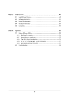
Table of Contents GA-8I915PL-G Motherboard Layout 6 Block Diagram ...7 Chapter 1 Hardware Installation 9 1-1 Considerations Prior to Installation 9 1-2 Feature Summary 10 1-3 Installation of the CPU and Heatsink 12 1-3-1 Installation of the CPU 12 1-3-2 Installation of the Heatsink 13 1-4 - Gigabyte GA-8I915PL-G | Manual - Page 5
4 Appendix 53 4-1 Unique Software Utilities 53 4-1-1 EasyTune 5 Introduction 54 4-1-2 Xpress Recovery Introduction 55 4-1-3 Flash BIOS Method Introduction 58 4-1-4 2- / 4- / 6- / 8- Channel Audio Function Introduction 67 4-1-5 Jack-Sensing and UAJ Introduction 71 4-2 Troubleshooting 73 - 5 - - Gigabyte GA-8I915PL-G | Manual - Page 6
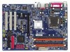
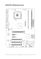
GA-8I915PL-G Motherboard Layout KB_MS ATX_12V LGA775 CPU_FAN COMA LPT LAN COMB ATX R_USB GA-8I915PL-G DDR1 DDR2 USB AUDIO1 AUDIO2 IT8712 F_AUDIO Intel 915PL PCIE_16 Marvell 8001 CODEC CD_IN PCIE_1 PCIE_2 BIOS IR SPDIF_IO CI SATA3 ICH6 SATA2 SATA1 PCI1 SATA0 SYS_FAN - Gigabyte GA-8I915PL-G | Manual - Page 7
) LGA775 Processor CPUCLK+/-(200/133MHz) PCI-ECLK (100MHz) PCI Express x16 Host Interface Intel 915PL MCH DDR 400/333MHz DIMM Dual Channel Memory MCHCLK (133/200MHz) 2 PCI Express x 1 Ports PCI Express x1 Bus PCI Bus Marvell 8001 RJ45 3 PCI Intel ICH6 CODEC 66MHz 33MHz 14.318MHz 48MHz BIOS - Gigabyte GA-8I915PL-G | Manual - Page 8
- 8 - - Gigabyte GA-8I915PL-G | Manual - Page 9
off the computer and unplug its power cord. 2. When handling the motherboard, avoid touching any metal leads or connectors. 3. It is best to wear an electrostatic discharge (ESD) cuff when handling electronic components (CPU, RAM). 4. Prior to installing the electronic components, please have these - Gigabyte GA-8I915PL-G | Manual - Page 10
Onboard LAN Onboard Audio Š Supports the latest Intel® Pentium® 4 LGA775 CPU Š Supports 800/533MHz FSB Š L2 cache varies with CPU Š Northbridge: Intel® 915PL Express Chipset Š Southbridge: Intel® ICH6 Š 2 DDR DIMM memory slots (supports up to 2GB memory) Š Supports 2.5V DDR DIMM Š Supports dual - Gigabyte GA-8I915PL-G | Manual - Page 11
/ System fan speed detection Š CPU warning temperature Š CPU / System fan failure warning Š CPU smart fan control Š Use of licensed AWARD BIOS Š Supports Q-Flash Š Supports @BIOS Š Supports EasyTune 5 Š Over Voltage via BIOS (CPU/DDR/PCI-E/FSB) Š Over Clock via BIOS (CPU/DDR/PCIE) Š ATX form factor - Gigabyte GA-8I915PL-G | Manual - Page 12
your thumb and forefinger, carefully place it into the socket in a straight and downwards motion. Avoid twisting or bending motions that might cause damage to the CPU during installation.) GA-8I915PL-G Motherboard - 12 - Fig. 4 Once the CPU is properly inserted, please replace the load plate and - Gigabyte GA-8I915PL-G | Manual - Page 13
the CPU and make sure the push pins aim to the pin hole on the motherboard.Pressing down the push pins diagonally. Fig. 4 Please make sure the Male and Female push pin are joined closely. (for detailed installation instructions, please refer to the heatsink installation section of the user manual - Gigabyte GA-8I915PL-G | Manual - Page 14
fit in one direction. Insert the DIMM memory module vertically into the DIMM socket. Then push it down. Fig.2 Close the plastic clip at both edges of the DIMM sockets to lock the DIMM module. Reverse the installation steps when you wish to remove the DIMM module. GA-8I915PL-G Motherboard - 14 - - Gigabyte GA-8I915PL-G | Manual - Page 15
English Dual Channel DDR GA-8I915PL-G supports the Dual Channel Technology. After operating the Dual Channel Technology, the bandwidth of Memory Bus will add double. GA-8I915PL-G includes 2 DIMM sockets, and each Channel has two DIMM sockets as following: Channel A : DDR 1 Channel B : DDR 2 If you - Gigabyte GA-8I915PL-G | Manual - Page 16
outlined below: 1. Read the related expansion card's instruction document before install the expansion card into the computer the computer, if necessary, setup BIOS utility of expansion card from BIOS. 8. Install related driver from the operating system. Installing a GA-8I915PL-G Motherboard - 16 - - Gigabyte GA-8I915PL-G | Manual - Page 17
support USB controller, please contact OS vendor for possible patch or driver upgrade. For more information please contact your OS or device(s) vendors. LAN Port The provided Internet connection is Gigabit Ethernet audio software to configure 2-/4-/6-/8-channel audio functioning. - 17 - Hardware - Gigabyte GA-8I915PL-G | Manual - Page 18
5) FDD 6) IDE1 7) SATA0 / SATA1 / SATA2 / SATA3 8) F_PANEL 9) PWR_LED 10) F_AUDIO 11) CD_IN 12) SPDIF_IO 13) F_USB1 / F_USB2 14) IR 15) CI 16) CLR_CMOS 17) BAT GA-8I915PL-G Motherboard - 18 - - Gigabyte GA-8I915PL-G | Manual - Page 19
all components and devices are properly installed. Align the power connector with its proper location on the motherboard and connect tightly. The ATX_12V power connector mainly supplies power to the CPU. If the ATX_12V power connector is not connected, the system will not start. Caution! Please use - Gigabyte GA-8I915PL-G | Manual - Page 20
. Caution! Please remember to connect the power to the CPU fan to prevent CPU overheating and failure. 1 CPU_FAN 1 SYS_FAN Pin No. supported are: 360KB, 720KB, 1.2MB, 1.44MB and 2.88MB. Please connect the red power connector wire to the pin1 position. 2 34 1 33 GA-8I915PL-G Motherboard - - Gigabyte GA-8I915PL-G | Manual - Page 21
the other as Slave (for information on settings, please refer to the instructions located on the IDE device). 2 40 1 39 7) SATA0/SATA1 provide 150MB/s transfer rate. Please refer to the BIOS setting for the Serial ATA and install the proper driver in order to work properly. Pin No. Definition - Gigabyte GA-8I915PL-G | Manual - Page 22
1: Power Pin 2- Pin 3: NC Pin 4: Data(-) Open: Normal Close: Reset Hardware System Open: Normal Close: Power On/Off Pin 1: LED anode(+) Pin 2: LED cathode(-) NC GA-8I915PL-G Motherboard - 22 - - Gigabyte GA-8I915PL-G | Manual - Page 23
header. To find out if the chassis you are buying support front audio connector, please contact your dealer.Please note, you can have the alternative of using front audio connector or of using rear audio connector to play sound. 10 9 2 1 Pin No. 1 2 3 4 5 6 7 8 9 10 Definition MIC GND MIC_BIAS - Gigabyte GA-8I915PL-G | Manual - Page 24
GND 4 CD-R 12) SPDIF_IO (SPDIF In/Out) The SPDIF output is capable of providing digital audio to external speakers or compressed AC3 data to an external Dolby Digital Decoder. Use this feature only when . 1 2 3 4 5 6 Definition Power No Pin SPDIF SPDIFI GND GND GA-8I915PL-G Motherboard - 24 - - Gigabyte GA-8I915PL-G | Manual - Page 25
to work or even damage it. For optional front USB cable, please contact your local dealer. The "USB Device Wake up From S3" is only supported by rear USB ports. Pin No. Definition 2 10 1 Power 2 Power 1 9 3 USB DX- 4 USB Dy- 5 USB DX+ 6 USB Dy+ 7 GND 8 GND 9 No Pin 10 NC 14 - Gigabyte GA-8I915PL-G | Manual - Page 26
Case Open) This 2-pin connector allows your system to enable or disable the "Case Open" item in BIOS, if the system case begin remove. Pin No. Definition 1 1 Signal 2 GND 16) CLR_CMOS ( from improper use this jumper. Open: Normal 1 1 Short: Clear CMOS GA-8I915PL-G Motherboard - 26 - - Gigabyte GA-8I915PL-G | Manual - Page 27
is incorrectly replaced. Replace only with the same or equivalent type recommended by the manufacturer. Dispose of used batteries according to the manufacturer's instructions. If you want to erase CMOS... 1.Turn OFF the computer and unplug the power cord. 2.Remove the battery, wait for 30 second - Gigabyte GA-8I915PL-G | Manual - Page 28
English GA-8I915PL-G Motherboard - 28 - - Gigabyte GA-8I915PL-G | Manual - Page 29
BIOS, either Gigabyte's Q-Flash or @BIOS utility can be used. Q-Flash allows the user to quickly and easily update or backup BIOS without entering the operating system. @BIOS is a Windows-based utility that does not require users to boot to DOS before upgrading BIOS but directly download and update - Gigabyte GA-8I915PL-G | Manual - Page 30
Supervisor Password Set User Password Save & Optimized Defaults in the BIOS when somehow the system CPU clock and frequency ratio. „ Load Fail-Safe Defaults Fail-Safe Defaults indicates the value of the system parameters which the system would be in safe configuration. GA-8I915PL-G Motherboard - Gigabyte GA-8I915PL-G | Manual - Page 31
and Setup, or just to Setup. „ Set User Password Change, set, or disable password. It Drive B Floppy 3 Mode Suport Halt On Base Memory Extended Memory Total Memory [None] [None] [None] [None] [None The week, from Sun to Sat, determined by the BIOS and is display only Month The month, Jan. Through - Gigabyte GA-8I915PL-G | Manual - Page 32
can use one of three methods: Auto Allows BIOS to automatically detect IDE devices during POST(default) None detection step and allow for faster system start up. Manual User can manually input the correct settings Access Mode Use this to ; 2.88M byte capacity. GA-8I915PL-G Motherboard - 32 - - Gigabyte GA-8I915PL-G | Manual - Page 33
English Floppy 3 Mode Support (for Japan Area) Disabled Normal Floppy Drive memory is typically 512K for systems with 512K memory installed on the motherboard, or 640K for systems with 640K or more memory installed on the motherboard. Extended Memory The BIOS determines how much extended memory - Gigabyte GA-8I915PL-G | Manual - Page 34
your boot device priority by USB-CDROM. USB-HDD Select your boot device priority by USB-HDD. LAN Select your boot device priority by LAN. Disabled Disable this function. (Note) This item will show up when you install a processor which supports this function. GA-8I915PL-G Motherboard - 34 - - Gigabyte GA-8I915PL-G | Manual - Page 35
system with multi processors mode supported. (Default value) Disabled Disables CPU Hyper Threading. Limit CPUID Max. to 3 Enabled Limit CPUID Maximum value to 3 when use older OS like NT4. Disabled Disables CPUID Limit for windows XP. (Default value) No-Execute Memory Protect (Note) Enabled - Gigabyte GA-8I915PL-G | Manual - Page 36
Controller USB 2.0 Controller USB Keyboard Support USB Mouse Support AC97 Audio Onboard H/W LAN Onboard LAN Boot ROM Onboard Serial Port 1 BIOS will auto detect. (Default value) Combined Set On-Chip SATA mode to Combined, you can use up to 4 HDDs on the motherboard GA-8I915PL-G Motherboard - 36 - - Gigabyte GA-8I915PL-G | Manual - Page 37
Support Enabled Enable USB Mouse Support. Disabled Disable USB Mouse Support. (Default value) AC97 Audio Auto Disabled Auto detect AC97 audio function. (Default value) Disable this function. Onboard H/W LAN Enabled Enable Onboard H/W LAN Serial Port 2 Auto BIOS will automatically setup - Gigabyte GA-8I915PL-G | Manual - Page 38
Using Parallel port as ECP & EPP mode. ECP Mode Use DMA 3 Set ECP Mode Use DMA to 3. (Default value) 1 Set ECP Mode Use DMA to 1. GA-8I915PL-G Motherboard - 38 - - Gigabyte GA-8I915PL-G | Manual - Page 39
ACPI suspend type to S1/POS(Power On Suspend). (Default value) Set ACPI suspend type to S3/STR(Suspend To RAM). Soft-off by PWR-BTTN Instant-off Press power button then Power off instantly. (Default value) Delay 4 Sec. click on PS/2 mouse left button to power on the system. - 39 - BIOS Setup - Gigabyte GA-8I915PL-G | Manual - Page 40
system, the system will be in "Off" state. (Default value) Full-On When AC-power back to the system, the system always in "On" state. Memory When AC-power back to the system, the system will return to the Last state before AC-power off. GA-8I915PL-G Motherboard - 40 - - Gigabyte GA-8I915PL-G | Manual - Page 41
IRQ 3,4,5,7,9,10,11,12,14,15 to PCI 2. Auto assign IRQ to PCI 3. (Default value) Set IRQ 3,4,5,7,9,10,11,12,14,15 to PCI 3. - 41 - BIOS Setup - Gigabyte GA-8I915PL-G | Manual - Page 42
/ 158oF. Monitor CPU temperature at 80oC / 176oF. Monitor CPU temperature at 90oC / 194oF. Disabled Disable this function. (Default value) CPU/SYSTEM FAN Fail Warning Disabled Fan warning function disable. (Default value) Enabled Fan warning function enable. GA-8I915PL-G Motherboard - 42 - - Gigabyte GA-8I915PL-G | Manual - Page 43
-Copyright (C) 1984-2004 Award Software MB Intelligent Tweaker(M.I.T.) CPU Clock Ratio Robust Graphics Booster C.I.A. 2 CPU Host Clock Control x CPU Host Frequency (Mhz) x PCI Experss Frequency (Mhz) Memory Frequency For Memory Frequency (Mhz) DIMM OverVoltage Control PCI-E OverVoltage Control - Gigabyte GA-8I915PL-G | Manual - Page 44
CPU Host Frequency" to 200MHz. Incorrect using it may cause your system broken. For power End-User Memory Frequency = Host clock X 2.5 3 Memory Frequency = Host clock X 3. 4 Memory Frequency = Host clock X 4. Auto Set Memory frequency by DRAM SPD data. (Default value) GA-8I915PL-G Motherboard - Gigabyte GA-8I915PL-G | Manual - Page 45
DIMM voltage, damage to the memory may occur. Normal Set DIMM your system broken. For power End-User use only! PCI-E OverVoltage Control your system broken. For power End-User use only! FSB OverVoltage Control Normal CPU Voltage Control Supports adjustable CPU Vcore from 0.8375V to 1. - Gigabyte GA-8I915PL-G | Manual - Page 46
` Advanced BIOS Features Load Optimized Defaults ` Integrated Peripherals Set Supervisor Password ` Power Management Setup Set User Password ` this field loads the factory defaults for BIOS and Chipset Features which the system automatically detects. GA-8I915PL-G Motherboard - 46 - - Gigabyte GA-8I915PL-G | Manual - Page 47
, the system will boot and you can enter Setup freely. The BIOS Setup program allows you to specify two separate passwords: SUPERVISOR PASSWORD and a USER PASSWORD. When disabled, anyone may access all BIOS Setup program function. When enabled, the Supervisor password is required for entering - Gigabyte GA-8I915PL-G | Manual - Page 48
` Advanced BIOS Features ` User Password Quit Without Saving (SYa/Nve)?&NExit Setup Exit Without Saving KLJI: Select Item F10: Save & Exit Setup Abandon all Data Type "Y" will quit the Setup Utility without saving to RTC CMOS. Type "N" will return to Setup Utility. GA-8I915PL-G Motherboard - Gigabyte GA-8I915PL-G | Manual - Page 49
will continue to install other drivers. System will reboot automatically after install the drivers, afterward you can install others application. For USB2.0 driver support under Windows XP operating system, please use Windows Service Pack. After install Windows Service Pack, it will show a question - Gigabyte GA-8I915PL-G | Manual - Page 50
Applications This page displays all the tools that Gigabyte developed and some free software, you can choose anyone you want and press "install" to install them. 3-3 Driver CD Information This page lists the contents of software and drivers in this CD-title. GA-8I915PL-G Motherboard - 50 - - Gigabyte GA-8I915PL-G | Manual - Page 51
English 3-4 Hardware Information This page lists all device you have for this motherboard. 3-5 Contact Us Please see the last page for details. - 51 - Install Drivers - Gigabyte GA-8I915PL-G | Manual - Page 52
English GA-8I915PL-G Motherboard - 52 - - Gigabyte GA-8I915PL-G | Manual - Page 53
Download Center allows users to quickly download and update their BIOS as well as the latest drivers for their system. Download Center automatically runs a system check of the user PC and provides the user with the current system information as well as displaying a detailed list of all new drivers - Gigabyte GA-8I915PL-G | Manual - Page 54
Easy and Advance Mode Display panel of CPU frequency Shows the current functions status Log on to GIGABYTE website Display EasyTuneTM 5 Help file Quit or Minimize EasyTuneTM 5 software (Note) EasyTune 5 functions may vary depending on different motherboards. GA-8I915PL-G Motherboard - 54 - - Gigabyte GA-8I915PL-G | Manual - Page 55
, the user can restore the drive to its original state. 1. Supports FAT16, BIOS menu, select "Advanced BIOS Feature" and set to boot from CD-ROM. Insert the provided driver CD into your CD drive, then save and exit the BIOS V1.0 (C) Copy Right 2003. GIGABYTE Technology CO. , Ltd. 1. Execute - Gigabyte GA-8I915PL-G | Manual - Page 56
BIOS for 8IPE1000MT F1 Check System Health OK . . . Press DEL to enter SETUP / Q-Flash, F9 For Xpress Recovery 08/16/2002-I845GE-6A69YG01C-00 F9 For Xpress Recovery Xpress Recovery V1.0 (C) Copy Right 2003. GIGABYTE driver and software installations are complete. GA-8I915PL-G Motherboard - 56 - - Gigabyte GA-8I915PL-G | Manual - Page 57
Esc to Exit The backup utility will automatically scan your system and back up data as a backup image in your hard drive. Not all systems support access to Xpress Recovery by pressing the F9 key during computer power on. If this is the case, please use the boot from CD-ROM - Gigabyte GA-8I915PL-G | Manual - Page 58
of updating BIOS to avoid any claims from end-users. Before You Begin: Before you start updating BIOS with the Q-FlashTM utility, please follow the steps below first. 1. Download the latest BIOS for your motherboard from Gigabyte's website. 2. Extract the BIOS file downloaded and save the BIOS file - Gigabyte GA-8I915PL-G | Manual - Page 59
Setup PnP/PCI Configurations PC Health Status MB Intelligent Tweaker(M.I.T.) ESC: Quit F8: Dual BIOS/Q-Flash Select Language Load Fail-Safe Defaults Load Optimized Defaults Set Supervisor Password Set User Password Save & Exit Setup Exit Without Saving F3: Change Language F10: Save & Exit Setup - Gigabyte GA-8I915PL-G | Manual - Page 60
Save Main BIOS to Floppy Save Backup BIOS to Floppy Enter : Run :Move ESC:Reset F10:Power Off Do not trun off power or reset your system at this stage!! After BIOS file is read, you'll see a confirmation dialog box asking you "Are you sure to update BIOS?" GA-8I915PL-G Motherboard - 60 - Gigabyte GA-8I915PL-G | Manual - Page 61
Fab after updating. Award Modular BIOS v6.00PG, An Energy Star Ally Copyright (C) 1984-2003, Award Software, Inc. Intel i875P AGPset BIOS for 8KNXP Ultra Fba Check System Health OK , VCore = 1.5250 Main Processor : Intel Pentium(R) 4 1.6GHz (133x12) Memory Testing - Gigabyte GA-8I915PL-G | Manual - Page 62
Two: Updating BIOS with Q-FlashTM Utility on Single-BIOS Motherboards. This part guides users of single-BIOS motherboards how to update BIOS using the User Password Save & Exit Setup Exit Without Saving F3: Change Language F10: Save & Exit Setup Time, Date, Hard Disk Type... GA-8I915PL-G Motherboard - Gigabyte GA-8I915PL-G | Manual - Page 63
Q-FlashTM utility Enter : Run Keep DMI Data Enable Update BIOS from Floppy Save BIOS to Floppy :Move ESC:Reset F10:Power Off Action download one BIOS file to the floppy disk so only one BIOS file, 8GE800.F4, is listed. Please confirm again you have the correct BIOS file for your motherboard - Gigabyte GA-8I915PL-G | Manual - Page 64
03/18/2003-I845GE-6A69YG01C-00 6. Press Del to enter BIOS menu after system reboots and "Load BIOS Fail-Safe Defaults". See how to Load BIOS Fail-Safe Defaults, please kindly refer to Step 6 to 7 in Part One. Congratulation!! You have updated BIOS successfully!! GA-8I915PL-G Motherboard - 64 - - Gigabyte GA-8I915PL-G | Manual - Page 65
the new @BIOS utility. @BIOS allows users to update their BIOS under Windows. Just select the desired @BIOS server to download the latest version of BIOS. Fig 1. Installing the @BIOS utility Fig 2. Installation Complete and Run @BIOS Click Sart/ Programs/ GIGABYTE/@BIOS Select @BIOS item than - Gigabyte GA-8I915PL-G | Manual - Page 66
won't boot. III. In method I, if the BIOS file you need cannot be found in @BIOSTM server, please go onto Gigabyte's web site for downloading and updating it according to method II. IV. Please note that any interruption during updating will cause system unbooted GA-8I915PL-G Motherboard - 66 - - Gigabyte GA-8I915PL-G | Manual - Page 67
in Windows XP) Stereo Speakers Connection and Settings: We recommend that you use the speaker with amplifier to acquire the best sound effect if the stereo output is applied. STEP 1: Connect the stereo speakers or earphone to "Line Out". Line Out STEP 2 : Following installation of the audio driver - Gigabyte GA-8I915PL-G | Manual - Page 68
of the audio driver, you find a Sound Effect icon on the lower right hand taskbar. Click the icon to select the function. STEP 3: Click "Speaker Configuration" then click on the left selection bar and select "4CH Speaker" to complete 4 channel audio configuration. GA-8I915PL-G Motherboard - 68 - Gigabyte GA-8I915PL-G | Manual - Page 69
channels to "Rear Speaker Out", and the Center/Subwoofer channels to "Center/Subwoofer Speaker Out". STEP 2 : Following installation of the audio driver, you find a Sound Effect icon on the lower right hand taskbar. Click the icon to select the function. STEP 3: Click "Speaker Configuration" then - Gigabyte GA-8I915PL-G | Manual - Page 70
installation of the audio driver, you find a Sound Effect icon on audio configuration. Sound Effect Configuration: At the sound effect menu, users can adjust sound option settings as desired. Front Speaker Out Rear Speaker Out Center/Subwoofer Speaker Out Side Speaker Out GA-8I915PL-G Motherboard - Gigabyte GA-8I915PL-G | Manual - Page 71
version before to enable Jack-Sensing support for Windows 98/98SE/2000/ME. Jack-Sensing includes 2 parts: AUTO and MANUAL. Following is an example for 2 channels (Windows XP): Introduction of audio connectors You may connect CDROM, Walkman or others audio input devices to Line In jack, speakers - Gigabyte GA-8I915PL-G | Manual - Page 72
jack (Line-in/ Line-out). That means users do not need to worry the audio device should be plug in Line-in or Line-out jack, the device will work perfectly after UAJ is activated. Enable UAJ function: You can click "UAJ Automatic" button to enable UAJ function. GA-8I915PL-G Motherboard - 72 - - Gigabyte GA-8I915PL-G | Manual - Page 73
English 4-2 Troubleshooting Below is a collection of general asked questions. To check general asked questions based on a specific motherboard model, please log on to http://www.gigabyte.com.tw Question 1: I cannot see some options that were included in previous BIOS after updating BIOS. Why? - Gigabyte GA-8I915PL-G | Manual - Page 74
user manual and check whether you have connected any cable that is not provided with the motherboard read/write error 11 beeps Cache memory bad AWARD BIOS Beep Codes 1 short: System boots BIOS ROM error Continuous long beeps: DRAM error Continuous short beeps: Power error GA-8I915PL-G Motherboard - Gigabyte GA-8I915PL-G | Manual - Page 75
- 75 - Appendix English - Gigabyte GA-8I915PL-G | Manual - Page 76
English GA-8I915PL-G Motherboard - 76 - - Gigabyte GA-8I915PL-G | Manual - Page 77
- 77 - Appendix English - Gigabyte GA-8I915PL-G | Manual - Page 78
English GA-8I915PL-G Motherboard - 78 - - Gigabyte GA-8I915PL-G | Manual - Page 79
Milton Keynes, MK1 1DR, UK, England TEL: +44-1908-362700 FAX: +44-1908-362709 Tech. Support : http://uk.giga-byte.com/TechSupport/ServiceCenter.htm Non-Tech. Support(Sales/Marketing) : http://ggts.gigabyte.com.tw/nontech.asp WEB address : http://uk.giga-byte.com The Netherlands GIGA-BYTE TECHNOLOGY - Gigabyte GA-8I915PL-G | Manual - Page 80
://www.gigabyte.ru Poland Representative Office Of Giga-Byte Technology Co., Ltd. POLAND Tech. Support : http://tw.giga-byte.com/TechSupport/ServiceCenter.htm Non-Tech. Support(Sales/Marketing) : http://ggts.gigabyte.com.tw/nontech.asp WEB address : http://www.gigabyte.pl GA-8I915PL-G Motherboard
-
 1
1 -
 2
2 -
 3
3 -
 4
4 -
 5
5 -
 6
6 -
 7
7 -
8
-
9
-
10
-
11
-
12
-
13
-
14
-
15
-
16
-
17
-
18
-
19
-
20
-
21
-
22
-
23
-
24
-
25
-
26
-
27
-
28
-
29
-
30
-
31
-
32
-
33
-
34
-
35
-
36
-
37
-
38
-
39
-
40
-
41
-
42
-
43
-
44
-
45
-
46
-
47
-
48
-
49
-
50
-
51
-
52
-
53
-
54
-
55
-
56
-
57
-
58
-
59
-
60
-
61
-
62
-
63
-
64
-
65
-
66
-
67
-
68
-
69
-
70
-
71
-
72
-
73
-
74
-
75
-
76
-
77
-
78
-
79
-
80
 |
 |

GA-8I915PL-G
Intel
®
Pentium
®
4 LGA775 Processor Motherboard
User's Manual
Rev. 1001
12ME-8I915PLG-1001