Gigabyte GA-8I925X-G Manual
Gigabyte GA-8I925X-G Manual
 |
View all Gigabyte GA-8I925X-G manuals
Add to My Manuals
Save this manual to your list of manuals |
Gigabyte GA-8I925X-G manual content summary:
- Gigabyte GA-8I925X-G | Manual - Page 1
GA-8I925X-G Intel® Pentium® 4 LGA775 Processor Motherboard User's Manual Rev. 2003 12ME-8I925XG-2003 - Gigabyte GA-8I925X-G | Manual - Page 2
Motherboard GA-8I925X-G Jul. 2, 2004 Motherboard GA-8I925X-G Jul. 2, 2004 - Gigabyte GA-8I925X-G | Manual - Page 3
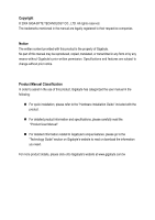
. „ For detailed product information and specifications, please carefully read the "Product User Manual". „ For detailed information related to Gigabyte's unique features, please go to the "Technology Guide" section on Gigabyte's website to read or download the information you need. For more product - Gigabyte GA-8I925X-G | Manual - Page 4
Table of Contents GA-8I925X-G Motherboard Layout 6 Block Diagram ...7 Chapter 1 Hardware Installation 9 1-1 Considerations Prior to Installation 9 1-2 Feature Summary 10 1-3 Installation of the CPU and Heatsink 12 1-3-1 Installation of the CPU 12 1-3-2 Installation of the Heatsink 13 1-4 - Gigabyte GA-8I925X-G | Manual - Page 5
Us ...49 Chapter 4 Appendix 51 4-1 Unique Software Utilities 51 4-1-1 Xpress Recovery Introduction 52 4-1-2 Flash BIOS Method Introduction 55 4-1-3 Serial ATA BIOS Setting Utility Introduction 66 4-1-4 2- / 4- / 6- / 8- Channel Audio Function Introduction 73 4-2 Troubleshooting 78 - 5 - - Gigabyte GA-8I925X-G | Manual - Page 6
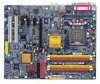
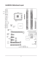
GA-8I925X-G Motherboard Layout DDRII1 DDRII2 DDRII4 DDRII5 KB_MS SPDIF_O SPDIF_I LGA775 GA-8I925X-G COM LPT USB USB LAN2 IT8712 AUDIO1 AUDIO2 ATX_12V CPU_FAN AZALIA_FP PCIE_16 Broadcom 5751 CODEC PCIE_1 PCIE_2 CD_IN PCIE_3 IR Main BIOS Backup BIOS Intel 925X PCI1 PCI2 F_USB1 - Gigabyte GA-8I925X-G | Manual - Page 7
925X Dual Channel Memory MCH MCHCLK (133/200MHz) 66MHz 33MHz 14.318MHz 48MHz Intel ICH6R Dual BIOS 4 Serial ATA ATA33/66/100 IDE Channels 2 PCI PCICLK (33MHz) CODEC 8 USB Ports use a DDRII 600 memory module on the motherboard, you must install an 800MHz FSB processor and overclock in - Gigabyte GA-8I925X-G | Manual - Page 8
- 8 - - Gigabyte GA-8I925X-G | Manual - Page 9
instructions below: 1. Please turn off the computer and unplug its power cord. 2. When handling the motherboard , avoid touching any metal leads or connectors. 3. It is best to wear an electrostatic discharge (ESD) cuff when handling electronic components (CPU motherboard problem manual - Gigabyte GA-8I925X-G | Manual - Page 10
LAN Onboard Audio Š Supports the latest Intel® Pentium® 4 LGA775 CPU Š Supports 800/533MHz FSB Š L2 cache varies with CPU Š Northbridge: Intel® 925X use a DDRII 600 memory module on the motherboard, you must install an 800MHz FSB processor and overclock in BIOS. GA-8I925X-G Motherboard - 10 - - Gigabyte GA-8I925X-G | Manual - Page 11
on the Win 2000/XP operating systems BIOS Š Use of licensed AWARD BIOS Š Supports Dual BIOS/Q-Flash/Multilanguage BIOS Additional Features Š Supports @BIOS Š Supports EasyTune Overclocking Š Over Voltage via BIOS (CPU/ DDR II/ PCI-E) Š Over Clock via BIOS (CPU/ DDR II) Form Factor Š ATX - Gigabyte GA-8I925X-G | Manual - Page 12
- CPU: An Intel® Pentium 4 Processor with HT Technology - Chipset: An Intel® Chipset that supports HT Technology - BIOS: A BIOS that supports HT that might cause damage to the CPU during installation.) GA-8I925X-G Motherboard - 12 - Fig. 4 Once the CPU is properly inserted, please replace the - Gigabyte GA-8I925X-G | Manual - Page 13
the CPU and make sure the push pins aim to the pin hole on the motherboard. Pressing down the push pins diagonally. Fig. 4 Please make sure the Male and Female push pin are joined closely. (for detailed installation instructions, please refer to the heatsink installation section of the user manual - Gigabyte GA-8I925X-G | Manual - Page 14
you are unable to insert the module, please switch the direction. The motherboard supports DDR II memory modules, whereby BIOS will automatically detect memory capacity and specifications. Memory modules are designed so steps when you wish to remove the DIMM module. GA-8I925X-G Motherboard - 14 - - Gigabyte GA-8I925X-G | Manual - Page 15
GA-8I925X-G supports the Dual Channel Technology. After operating the Dual Channel Technology, the bandwidth of Memory Bus will add double up to 8.5GB/s(DDR400). GA-8I925X same storage capacity in order to use dual channel memory and for BIOS to detect all the DDR II memory modules. We'll strongly - Gigabyte GA-8I925X-G | Manual - Page 16
outlined below: 1. Read the related expansion card's instruction document before install the expansion card into the computer on the computer, if necessary, setup BIOS utility of expansion card from BIOS. 8. Install related driver from the operating system. Installing a GA-8I925X-G Motherboard - 16 - - Gigabyte GA-8I925X-G | Manual - Page 17
USB controller. If your OS does not support USB controller, please contact OS ven dor for possible patch or driver upgrade. For more information please contact your OS or device(s) vendors. LAN Port The provided Internet connection is Gigabit Ethernet(PCI Express Gigabit), providing data transfer - Gigabyte GA-8I925X-G | Manual - Page 18
Connector) 10) BAT 3) CPU_FAN 11) F_PANEL 4) SYS_FAN 12) AZALIA_FP 5) PWR_FAN 13) CD_IN 6) FDD 14) F_USB1 / F_USB2 7) IDE 15) IR 8) SATA0_SB/SATA1_SB/SATA2_SB/SATA3_SB 16) CLR_CMOS GA-8I925X-G Motherboard - 18 - - Gigabyte GA-8I925X-G | Manual - Page 19
all components and devices are properly installed. Align the power connector with its proper location on the motherboard and connect tightly. The ATX_12V power connector mainly supplies power to the CPU. If the ATX_12V power connector is not connected, the system will not start. Caution! Please use - Gigabyte GA-8I925X-G | Manual - Page 20
failure. Caution! Please remember to connect the power to the CPU fan to prevent CPU overheating and failure. 1 CPU_FAN Pin No. 1 2 3 supported are: 360KB, 720KB, 1.2MB, 1.44MB and 2.88MB. Please connect the red power connector wire to the pin1 position. 2 34 1 33 GA-8I925X-G Motherboard - - Gigabyte GA-8I925X-G | Manual - Page 21
other as Slave (for information on settings, please refer to the instructions located on the IDE device). 2 40 1 39 8) SATA0_SB / can provide 150MB/s transfer rate. Please refer to the BIOS setting for the Serial ATA and install the proper driver in order to work properly. Pin No. Definition - Gigabyte GA-8I925X-G | Manual - Page 22
+ 2 MPD- 1 3 MPD- 10) BAT(Battery) GA-8I925X-G Motherboard Danger of explosion if battery is incorrectly replaced. Replace only with the same or equivalent type recommended by the manufacturer. Dispose of used batteries according to the manufacturer's instructions. If you want to erase CMOS - Gigabyte GA-8I925X-G | Manual - Page 23
English 11) F_PANEL (Front Panel Jumper) Please connect the power LED, PC peaker, reset switch and power switch etc of your chassis front panel to the F_PANEL connector according to the pin assignment below. Speaker Connector Power Switch Message LED/ Power/ Sleep LED SPEAK- 20 19 SPEAK+ PWPW+ - Gigabyte GA-8I925X-G | Manual - Page 24
pin assigment on the cable is the same as the pin assigment on the motherboard header. To find out if the chassis you are buying support front audio panel connector, please contact your dealer. 10 9 2 1 Pin No. Definition 1 1 CD-L 2 GND 3 GND 4 CD-R GA-8I925X-G Motherboard - 24 - - Gigabyte GA-8I925X-G | Manual - Page 25
to work or even damage it. For optional front USB cable, please contact your local dealer. The "USB Device Wake up From S3" is only supported by rear USB ports. 2 10 1 9 Pin No. 1 2 3 4 5 6 7 8 9 10 Definition Power Power USB DXUSB DyUSB DX+ USB Dy+ GND GND No Pin NC 15) IR Be - Gigabyte GA-8I925X-G | Manual - Page 26
English 16) CLR_CMOS (Clear CMOS) You may clear the CMOS data to its default values by this jumper. To clear CMOS, temporarily short 1-2 pin. Default doesn't include the "Shunter" to prevent from improper use this jumper. Open: Normal 1 Short: Clear CMOS 1 GA-8I925X-G Motherboard - 26 - - Gigabyte GA-8I925X-G | Manual - Page 27
its original settings. If you wish to upgrade to a new BIOS, either Gigabyte's Q-Flash or @BIOS utility can be used. Q-Flash allows the user to quickly and easily update or backup BIOS without entering the operating system. @BIOS is a Windows-based utility that does not require users to boot to DOS - Gigabyte GA-8I925X-G | Manual - Page 28
Defaults in the BIOS when somehow the CPU clock and frequency ratio. „ Select Language This setup page is select multi language. „ Load Fail-Safe Defaults Fail-Safe Defaults indicates the value of the system parameters which the system would be in safe configuration. GA-8I925X-G Motherboard - Gigabyte GA-8I925X-G | Manual - Page 29
system. „ Save & Exit Setup Save CMOS value settings to CMOS and exit setup. „ Exit Without Saving Abandon all CMOS value changes and exit setup. - 29 - BIOS Setup - Gigabyte GA-8I925X-G | Manual - Page 30
. Week Month The week, from Sun to Sat, determined by the BIOS and is display only The month, Jan. Through Dec. Day The day, detection step and allow for faster system start up. Manual User can manually input the correct settings Access Mode Use this to GA-8I925X-G Motherboard - 30 - - Gigabyte GA-8I925X-G | Manual - Page 31
inch double-sided drive; 2.88M byte capacity. Floppy 3 Mode Support (for Japan Area) Disabled Normal Floppy Drive. (Default value) motherboard. Extended Memory The BIOS determines how much extended memory is present during the POST. This is the amount of memory located above 1 MB in the CPU - Gigabyte GA-8I925X-G | Manual - Page 32
Utility-Copyright (C) 1984-2004 Award Software Advanced BIOS Features ` Hard Disk Boot Priority First Boot Device Second Boot Device Third Boot Device Password Check # CPU Hyper-Threading Limit CPUID Max. to 3 if the correct password is not entered at the prompt. GA-8I925X-G Motherboard - 32 - - Gigabyte GA-8I925X-G | Manual - Page 33
working Disabled for operating system with multi processors mode supported. (Default value) Disables CPU Hyper Threading. Limit CPUID Max. to 3 Enabled Disabled Limit CPUID Maximum value to 3 when use older OS like NT4. (Default value) Disables CPUID Limit for windows XP. - 33 - BIOS Setup - Gigabyte GA-8I925X-G | Manual - Page 34
(Default value) Disabled Disable onboard 1st channel IDE port. SATA RAID / AHCI Mode RAID Select onboard Seria ATA function as RAID. (Default value) AHCI Support hotplug function under OS. WinXP, 2000 only. Disabled Select onboard Seria ATA function as ATA. GA-8I925X-G Motherboard - 34 - - Gigabyte GA-8I925X-G | Manual - Page 35
Disabled Disable this function. Auto Combined BIOS will auto detect. (Default value) Set On-Chip SATA mode to Combined, you can use up to 4 HDDs on the Enhanced motherboard; 2 for SATA and the other for PATA IDE. Set On-Chip SATA mode to Enhanced, the motherboard allows up to 6 HDDs to use - Gigabyte GA-8I925X-G | Manual - Page 36
Serial port 1 and address is 2E8. Disabled Disable onboard Serial port 1. Onboard IrDA Port Auto BIOS will automatically setup the port 1 address. 3F8/IRQ4 2F8/IRQ3 Enable onboard IrDA port and address DMA to 3. (Default value) 1 Set ECP Mode Use DMA to 1. GA-8I925X-G Motherboard - 36 - - Gigabyte GA-8I925X-G | Manual - Page 37
) Power On by Mouse Disabled Disabled this function. (Default value) Double Click Double click on PS/2 mouse left button to power on the system. - 37 - BIOS Setup - Gigabyte GA-8I925X-G | Manual - Page 38
system always in "On" state. Memory When AC-power back to the system, the system will return to the Last state before AC-power off. GA-8I925X-G Motherboard - 38 - - Gigabyte GA-8I925X-G | Manual - Page 39
IRQ 3,4,5,7,9,10,11,12,14,15 to PCI 1. Auto assign IRQ to PCI 2. (Default value) Set IRQ 3,4,5,7,9,10,11,12,14,15 to PCI 2. - 39 - BIOS Setup - Gigabyte GA-8I925X-G | Manual - Page 40
Celsius, CPU fan will run at full speed. b. The speed of CPU fan will increase linearly depand on the temperature if the temperature is more than 41 degree and less than 65 degree. c. When the CPU temperature is lower than 40 degrees Celsius, CPU fan will be disable. GA-8I925X-G Motherboard - 40 - Gigabyte GA-8I925X-G | Manual - Page 41
English CPU FAN PIN Type In order to make "CPU Smart FAN Control" function work properly, please set the pin number according to the CPU FAN that you used. 3 PIN Set CPU FAN Type to 3 pins. (Default value) 4 PIN Set CPU FAN Type to 4 pins. - 41 - BIOS Setup - Gigabyte GA-8I925X-G | Manual - Page 42
is overclocked and cannot restart, please wait 20 seconds for automatic system restart or clear the CMOS setup data and perform a safe restart. Disabled Disable CPU host clock control. (Default value) Enabled Enable CPU host clock control. GA-8I925X-G Motherboard - 42 - - Gigabyte GA-8I925X-G | Manual - Page 43
3V. CPU Voltage Control Supports adjustable CPU Vcore from 0.8375V to 1.6000V. (Default value: Normal) Warning: CPU may be damaged or reduce CPU life-cycle when CPU is over-voltage. Normal CPU Vcore Display your CPU vcore voltage. (Note) To use a DDRII 600 memory module on the motherboard, you - Gigabyte GA-8I925X-G | Manual - Page 44
Save & Exit Setup Multi-language supports 7 languages. There are English, BIOS/Q-Flash F3: Change Language F10: Save & Exit Setup Load Fail-Safe Defaults Fail-Safe defaults contain the most appropriate values of the system parameters that allow minimum system performance. GA-8I925X-G Motherboard - Gigabyte GA-8I925X-G | Manual - Page 45
program and having full configuration fields, the User password is required to access only basic items. If you select "System" at "Password Check" in Advance BIOS Features Menu, you will be prompted for the password every time the system is rebooted or any time you try to enter Setup Menu. If - Gigabyte GA-8I925X-G | Manual - Page 46
CMOS and EXITSa(Yve/N&)?EYxit Setup ` MB Intelligent Tweaker(M.I.T.) Exit Without Saving ESC: Quit F8: Dual BIOS/Q-Flash F3: Change Language F10: Save & Exit Setup Save & Exit Setup Type "Y" will quit saving to RTC CMOS. Type "N" will return to Setup Utility. GA-8I925X-G Motherboard - 46 - - Gigabyte GA-8I925X-G | Manual - Page 47
will continue to install other drivers. System will reboot automatically after install the drivers, afterward you can install others application. For USB2.0 driver support under Windows XP operating system, please use Windows Service Pack. After install Windows Service Pack, it will show a question - Gigabyte GA-8I925X-G | Manual - Page 48
Software Applications This page displays all the tools that Gigabyte developed and some free software, you can choose anyone you want and press "install" to install them. 3-3 Driver CD Information This page lists the contents of software and drivers in this CD-title. GA-8I925X-G Motherboard - 48 - - Gigabyte GA-8I925X-G | Manual - Page 49
English 3-4 Hardware Information This page lists all device you have for this motherboard. 3-5 Contact Us Please see the last page for details. - 49 - Drivers Installation - Gigabyte GA-8I925X-G | Manual - Page 50
English GA-8I925X-G Motherboard - 50 - - Gigabyte GA-8I925X-G | Manual - Page 51
) Motherboard Intelligent Tweaker (M.I.T.) allows user to access and change BIOS feature settings with relative speed and ease. Through GIGABYTE M.I.T. feature the user is no longer required to switch into different modes within BIOS setup in order to change system settings such as the CPU system - Gigabyte GA-8I925X-G | Manual - Page 52
power on. . . Verifying DMI Pool Data Boot from CD: Boot from CD: Xpress Recovery V1.0 (C) Copy Right 2003. GIGABYTE Technology CO. , Ltd. 1. Execute Backup Utility 2. Execute Restore Utility 3. Remove Backup Image 4. Set Password 5. Exit and Restart Build 2011 GA-8I925X-G Motherboard - 52 - - Gigabyte GA-8I925X-G | Manual - Page 53
Energy Star Al ly Copyright (C) 1984-2004, Award Software, Inc. Intel 865PE AGPSet BIOS for 8IPE1000MT F1 Check System Health OK . . . Press DEL to enter SETUP / Q-Flash, F9 For Xpress Recovery 08/16/2002-I845GE-6A69YG01C-00 F9 For Xpress Recovery Xpress Recovery V1.0 (C) Copy Right 2003. GIGABYTE - Gigabyte GA-8I925X-G | Manual - Page 54
your system and back up data as a backup image in your hard drive. Not all systems support access to Xpress Recovery by pressing the F9 key during computer power on. If this is the case remove password requirement. 5. Exit and Restart: Exit and restart your computer. GA-8I925X-G Motherboard - 54 - - Gigabyte GA-8I925X-G | Manual - Page 55
Method Introduction A. What is Dual BIOS Technology? Dual BIOS means that there are two system BIOS (ROM) on the motherboard, one is the Main BIOS and the other is Backup BIOS. Under the normal circumstances, the system works on the Main BIOS. If the Main BIOS is corrupted or damaged, the Backup - Gigabyte GA-8I925X-G | Manual - Page 56
that the Backup BIOS works normally and could automatically recover the Main BIOS. (This auto recovery utility is set by system automatically and can't be changed by user.) Load Default Settings Load dual BIOS default value. Save Settings to CMOS Save revised setting. GA-8I925X-G Motherboard - 56 - Gigabyte GA-8I925X-G | Manual - Page 57
of Gigabyte motherboards are equipped with dual BIOS. In the BIOS menu of the motherboards supporting Q-Flash and Dual BIOS, the Q-Flash utility and Dual BIOS utility are combined in the same screen. This section only deals with how to use Q-Flash utility. In the following sections, we take GA-8KNXP - Gigabyte GA-8I925X-G | Manual - Page 58
Enter key on your keyboard to enable execution of the task. Action bar: Contains the names of four actions needed to operate the Q-Flash/Dual BIOS utility. Pressing the buttons mentioned on your keyboards to perform these actions. GA-8I925X-G Motherboard - 58 - - Gigabyte GA-8I925X-G | Manual - Page 59
using the Q-Flash utility. As described in the "Before you begin" section above, you must prepare a floppy disk having the BIOS file for your motherboard and insert it to your computer. If you have already put the floppy disk into your system and have entered the Q-Flash utility, please follow - Gigabyte GA-8I925X-G | Manual - Page 60
find the BIOS version on your boot screen becomes the one you flashed. The BIOS file becomes Fab after updating. Award Modular BIOS v6.00PG, An Energy Star Ally Copyright DEL to enter SETUP / Dual BIOS / Q-Flash / F9 For Xpress Recovery 09/23/2003-i875P-6A79BG03C-00 GA-8I925X-G Motherboard - 60 - - Gigabyte GA-8I925X-G | Manual - Page 61
Disk Type... Press Y on your keyboard to save and exit. Part Two: Updating BIOS with Q-FlashTM Utility on Single-BIOS Motherboards. This part guides users of single-BIOS motherboards how to update BIOS using the Q-FlashTM utility. CMOS Setup Utility-Copyright (C) 1984-2004 Award Software Standard - Gigabyte GA-8I925X-G | Manual - Page 62
SyCs:tRemeset F10:Power Off Do not trun off power or reset your system at this stage!! After BIOS file is read, you'll see a confirmation dialog box asking you "Are you sure to update BIOS?" Please do not take out the floppy disk when it begins flashing BIOS. GA-8I925X-G Motherboard - 62 - - Gigabyte GA-8I925X-G | Manual - Page 63
version on your boot screen becomes the one you flashed. The BIOS file becomes F4 after updating Award Modular BIOS v6.00PG, An Energy Star Ally Copyright (C) 1984-2003, Award Software, Inc. Intel 845GE AGPSet BIOS for 8GE800 F4 Check System Health OK Main Processor : Intel Pentium(R) 4 1.7GHz - Gigabyte GA-8I925X-G | Manual - Page 64
" icon. b. Click "Update New BIOS". c. Please select "All Files" in dialog box while opening the old file. d. Please search for BIOS unzip file, downloading from internet or any other methods (such as: 8I9XG.F1). e. Complete update process following the instruction. GA-8I925X-G Motherboard - 64 - - Gigabyte GA-8I925X-G | Manual - Page 65
II. In method II, be sure that motherboard's model name in BIOS unzip file are the same as your motherboard's. Otherwise, your system won't boot. III. In method I, if the BIOS file you need cannot be found in @BIOSTM server, please go onto Gigabyte's website for downloading and updating it according - Gigabyte GA-8I925X-G | Manual - Page 66
English 4-1-3 Serial ATA BIOS Setting Utility Introduction RAID Levels member. The striping block size can be set from 4KB to 64KB. RAID 0 does not support fault tolerance. RAID 1 (Mirroring) RAID 1 writes duplicate data onto a pair of drives and drives in the array. GA-8I925X-G Motherboard - 66 - - Gigabyte GA-8I925X-G | Manual - Page 67
motherboard BIOS and locate RAID setup (Please refer to the section on Integrated Peripherals). 4) Enter RAID setup in the BIOS and select the RAID type (For instance, enter Ctrl + I to select Intel RAID; Ctrl + S to select Silicon Image). 5) Complete driver I before the window disappears. Intel(R) - Gigabyte GA-8I925X-G | Manual - Page 68
]-Previous Menu [ENTER]-Select There are two RAID levels: RAID0(Stripe) and RAID1(Mirror). After selecting the RAID level, press Enter to select Strip Size. GA-8I925X-G Motherboard - 68 - - Gigabyte GA-8I925X-G | Manual - Page 69
English The KB is a unit of Strip Size. You can set disk block size with this item. The disk block size can be set from 4KB to 128KB. After you set disk block size, press Enter to set disk Capacity. Intel(R) Application Accelerator RAID Option ROM v4.0.6180 Copyright(C) 2003-04 Intel Corporation. - Gigabyte GA-8I925X-G | Manual - Page 70
LOST. Are you sure you want to creat this volume? (Y/N) : Press "ENTER" to Create the specified volume [ ]-Change [TAB]-Next [ESC]-Previous Menu [ENTER]-Select GA-8I925X-G Motherboard - 70 - - Gigabyte GA-8I925X-G | Manual - Page 71
Status 223.5GB Normal Bootable Yes Physical Disks : Port Driver Model 0 ST3120026AS 1 ST3120026AS Serial # 3JT354CP 3JT329JX Size select the Delete RAID Volume option. Press Enter key and follow the instructions on the screen. Intel(R) Application Accelerator RAID Option ROM v4.0.6180 - Gigabyte GA-8I925X-G | Manual - Page 72
time you add a new hard drive to a RAID array, the RAID driver will have to be installed under Windows once for that hard drive. After that, the driver will not have to be installed.) Note: In the menu list, Intel Application Accelerator 4.0 is Intel ICH6R chipset. GA-8I925X-G Motherboard - 72 - - Gigabyte GA-8I925X-G | Manual - Page 73
simple. Please follow the steps to install the function.(Following pictures are in Windows XP) Stereo Speakers Connection and Settings: We recommend that you use the speaker with amplifier to acquire the best sound effect if the stereo output is applied. STEP 1: Connect the stereo speakers or - Gigabyte GA-8I925X-G | Manual - Page 74
of the audio driver, you find a Sound Effect icon on the lower right hand taskbar. Click the icon to select the function. STEP 3: Click "Speaker Configuration" then click on the left selection bar and select "4CH Speaker" to complete 4 channel audio configuration. GA-8I925X-G Motherboard - 74 - Gigabyte GA-8I925X-G | Manual - Page 75
to "Rear Speaker Out", and the Center/Subwoofer channels to "Center/Subwoofer Speaker Out". STEP 2 : Following installation of the audio driver, you find a Sound Effect icon on the lower right hand taskbar. Click the icon to select the function. STEP 3: Click "Speaker Configuration" then click - Gigabyte GA-8I925X-G | Manual - Page 76
Following installation of the audio driver, you find a Sound Effect icon on the lower Sound Effect Configuration: At the sound effect menu, users can adjust sound option settings as desired. Front Speaker Out Rear Speaker Out Center/Subwoofer Speaker Out Side Speaker Out GA-8I925X-G Motherboard - Gigabyte GA-8I925X-G | Manual - Page 77
function. Install Microsoft DirectX8.1 or later version before to enable Jack-Sensing support for Windows 2000. After you install an audio device, a screen of a list to the correct jack following the arrow instruction. The correct icon for audio device will be displayed after the reinstallation. - - Gigabyte GA-8I925X-G | Manual - Page 78
manual and check whether you have connected any cable that is not provided with the motherboard package to the USB Over Current pin in the Front USB Panel. If the cable is your own cable, please remove it from this pin and do not connect any of your own cables to it. GA-8I925X-G Motherboard - Gigabyte GA-8I925X-G | Manual - Page 79
usually stand for? Answer: The beep codes below may help you identify the possible computer problems. However, they are only for reference purposes. The situations might differ from case to case. J AMI BIOS Beep Codes *Computer gives 1 short beep when system boots successfully. *Except for beep code - Gigabyte GA-8I925X-G | Manual - Page 80
English GA-8I925X-G Motherboard - 80 - - Gigabyte GA-8I925X-G | Manual - Page 81
- 81 - Appendix English - Gigabyte GA-8I925X-G | Manual - Page 82
English GA-8I925X-G Motherboard - 82 - - Gigabyte GA-8I925X-G | Manual - Page 83
- 83 - Appendix English - Gigabyte GA-8I925X-G | Manual - Page 84
English GA-8I925X-G Motherboard - 84 - - Gigabyte GA-8I925X-G | Manual - Page 85
- 85 - Appendix English - Gigabyte GA-8I925X-G | Manual - Page 86
English GA-8I925X-G Motherboard - 86 - - Gigabyte GA-8I925X-G | Manual - Page 87
Milton Keynes, MK1 1DR, UK, England TEL: +44-1908-362700 FAX: +44-1908-362709 Tech. Support : http://uk.giga-byte.com/TechSupport/ServiceCenter.htm Non-Tech. Support(Sales/Marketing) : http://ggts.gigabyte.com.tw/nontech.asp WEB address : http://uk.giga-byte.com The Netherlands GIGA-BYTE TECHNOLOGY - Gigabyte GA-8I925X-G | Manual - Page 88
www.gigabyte.ru Poland Representative Office Of Giga-Byte Technology Co., Ltd. POLAND Tech. Support : http://tw.giga-byte.com/TechSupport/ServiceCenter.htm Non-Tech. Support(Sales/Marketing) : http://ggts.gigabyte.com.tw/nontech.asp WEB address : http://www.gigabyte.pl GA-8I925X-G Motherboard - 88
-
 1
1 -
 2
2 -
 3
3 -
 4
4 -
 5
5 -
 6
6 -
 7
7 -
8
-
9
-
10
-
11
-
12
-
13
-
14
-
15
-
16
-
17
-
18
-
19
-
20
-
21
-
22
-
23
-
24
-
25
-
26
-
27
-
28
-
29
-
30
-
31
-
32
-
33
-
34
-
35
-
36
-
37
-
38
-
39
-
40
-
41
-
42
-
43
-
44
-
45
-
46
-
47
-
48
-
49
-
50
-
51
-
52
-
53
-
54
-
55
-
56
-
57
-
58
-
59
-
60
-
61
-
62
-
63
-
64
-
65
-
66
-
67
-
68
-
69
-
70
-
71
-
72
-
73
-
74
-
75
-
76
-
77
-
78
-
79
-
80
-
81
-
82
-
83
-
84
-
85
-
86
-
87
-
88
 |
 |

GA-8I925X-G
Intel
®
Pentium
®
4 LGA775 Processor Motherboard
User's Manual
Rev. 200
3
12ME-8I925XG-200
3