Gigabyte GA-8I945GME Manual
Gigabyte GA-8I945GME Manual
 |
View all Gigabyte GA-8I945GME manuals
Add to My Manuals
Save this manual to your list of manuals |
Gigabyte GA-8I945GME manual content summary:
- Gigabyte GA-8I945GME | Manual - Page 1
GA-8I945GME Intel® Pentium® 4 LGA775 Processor Motherboard User's Manual Rev. 1002 12ME-945GME-1002R * The WEEE marking on the product indicates this product must not be disposed of with user's other household waste and must be handed over to a designated collection point for the recycling of waste - Gigabyte GA-8I945GME | Manual - Page 2
Motherboard GA-8I945GME Dec. 10, 2005 Motherboard GA-8I945GME Dec. 10, 2005 - Gigabyte GA-8I945GME | Manual - Page 3
product information and specifications, please carefully read the "Product User Manual". „ For detailed information related to Gigabyte's unique features, please go to "Technology Guide" section on Gigabyte's website to read or download the information you need. For more product details, please - Gigabyte GA-8I945GME | Manual - Page 4
GA-8I945GME Motherboard Layout 6 Block Diagram ...7 Chapter 1 Hardware Installation 9 1-1 Considerations Prior to Installation 9 1-2 Feature Summary 10 1-3 Installation of the CPU and Heatsink 12 1-3-1 Installation of the CPU 48 2-10 Set Supervisor/User Password 49 2-11 Save & Exit Setup 50 2-12 - Gigabyte GA-8I945GME | Manual - Page 5
Chapter 3 Install Drivers 53 3-1 Install Chipset Drivers 53 3-2 SoftwareApplications 54 3-3 Driver CD Information 54 3-4 Hardware Information Recovery2 Introduction 59 4-1-3 Flash BIOS Method Introduction 62 4-1-4 2 / 4 / 6 Channel Audio Function Introduction 71 4-2 Troubleshooting 77 - 5 - - Gigabyte GA-8I945GME | Manual - Page 6
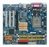
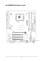
GA-8I945GME Motherboard Layout KB_MS ATX_12V LGA775 CPU_FAN IT8712F COMA GA-8I945GME ATX LPT LAN VGA R_USB USB SYS_FAN AUDIO F_AUDIO PCIE_16 PCI1 RTL 8110S PCI2 SPDIF_IO CODEC PCI3 SUR_CEN CD_IN AUX_IN COMB Intel 945G DDRII2 DDRII1 IDE FDD SATAIIO SATAII2 SATAII1 SATAII3 - Gigabyte GA-8I945GME | Manual - Page 7
Center/Subwoofer Speaker Out Side Speaker Out MIC Line-Out Line-In SPDIF In SPDIF Out (Note) To use a DDRII 667 memory module on the motherboard, you must install an 800/1066MHz FSB processor . - 7 - - Gigabyte GA-8I945GME | Manual - Page 8
- 8 - - Gigabyte GA-8I945GME | Manual - Page 9
, please follow the instructions below: 1. Please turn off the computer and unplug its power cord. 2. When handling the motherboard, avoid touching any metal leads or connectors. 3. It is best to wear an electrostatic discharge (ESD) cuff when handling electronic components (CPU, RAM). 4. Prior to - Gigabyte GA-8I945GME | Manual - Page 10
connector Š 1 front audio connector Š 1 CD In connector Š 1 AUX In connector Š 1 COMB connector Š 2 USB 2.0/1.1 connectors for additional 4 USB 2.0/1.1 ports by cables Š 1 SUR_CEN connector Š 1 SPDIF In/Out connector Š 1 power LED connector Š 1 TPM connector GA-8I945GME Motherboard - 10 - - Gigabyte GA-8I945GME | Manual - Page 11
version) Form Factor Š Micro ATX form factor; 24.4cm x 22.0cm (Note 1) For further CPU support information, please go to GIGABYTE's website. (Note 2) To use a DDRII 667 memory module on the motherboard, you must install an 800/1066MHz FSB processor . (Note 3) EasyTune functions may vary depending - Gigabyte GA-8I945GME | Manual - Page 12
the motherboard supports the CPU. 2. Please take note of the one indented corner of the CPU. If you install the CPU in the wrong direction, the CPU that might cause damage to the CPU during installation.) GA-8I945GME Motherboard - 12 - Fig. 4 Once the CPU is properly inserted, please replace the - Gigabyte GA-8I945GME | Manual - Page 13
the CPU and make sure the push pins aim to the pin hole on the motherboard.Pressing down the push pins diagonally. Fig. 4 Please make sure the Male and Female push pin are joined closely. (for detailed installation instructions, please refer to the heatsink installation section of the user manual - Gigabyte GA-8I945GME | Manual - Page 14
direction. If you are unable to insert the module, please switch the direction. The motherboard supports DDR II memory modules, whereby BIOS will automatically detect memory capacity and specifications. Memory modules steps when you wish to remove the DIMM module. GA-8I945GME Motherboard - 14 - - Gigabyte GA-8I945GME | Manual - Page 15
English Dual Channel Memory Configuration The GA-8I945GME supports the Dual Channel Technology. After operating the Dual Channel Technology, the bandwidth of Memory Bus will add double. The GA-8I945GME includes 2 DIMM sockets. If you want to operate the Dual Channel Technology, please note the - Gigabyte GA-8I945GME | Manual - Page 16
outlined below: 1. Read the related expansion card's instruction document before install the expansion card into the , setup BIOS utility of expansion card from BIOS. 8. Install related driver from the operating system. Installing a PCI Express x 16 expansion card GA-8I945GME Motherboard - 16 - - Gigabyte GA-8I945GME | Manual - Page 17
USB controller. If your OS does not support USB controller, please contact OS vendor for possible patch or driver upgrade. For more information please contact your OS or device(s) vendors. LAN Port The LAN port provides Internet connection. Line In Devices like CD-ROM, walkman etc. can be connected - Gigabyte GA-8I945GME | Manual - Page 18
14) SUR_CEN 5) FDD 15) F_USB1/F_USB2 6) IDE 16) COMB 7) SATAII0 / SATAII1 / SATAII2 / SATAII3 17) CLR_CMOS 8) F_AUDIO 18) CI 9) PWR_LED 19) BAT 10) F_PANEL 20) TPM GA-8I945GME Motherboard - 18 - - Gigabyte GA-8I945GME | Manual - Page 19
the power connector, please make sure that all components and devices are properly installed. Align the power connector with its proper location on the motherboard and connect tightly. The ATX_12V power connector mainly supplies power to the CPU. If the ATX_12V power connector is not connected, the - Gigabyte GA-8I945GME | Manual - Page 20
failure. Caution! Please remember to connect the power to the CPU fan to prevent CPU overheating and failure. 1 CPU_FAN 1 SYS_FAN Pin No. 1 supported are: 360KB, 720KB, 1.2MB, 1.44MB and 2.88MB. Please connect the red power connector wire to the pin1 position. 34 33 GA-8I945GME Motherboard 2 - Gigabyte GA-8I945GME | Manual - Page 21
, please refer to the instructions located on the IDE device). 40 39 2 1 7) SATAII0/SATAII1/SATAII2/SATAII3 (SATA 3Gb/s Connector) SATA 3Gb/s can provide up to 300MB/s transfer rate. Please refer to the BIOS setting for the Serial ATA II and install the proper driver - Gigabyte GA-8I945GME | Manual - Page 22
Return R NC No Pin Front Audio (L) Rear Audio (L)/ Return L 9) PWR_LED PWR_LED is connect with the system power indicator to indicate whether the system is on/off. It will blink when the system enters suspend mode. Pin No. Definition 1 1 MPD+ 2 MPD- 3 MPD- GA-8I945GME Motherboard - 22 - - Gigabyte GA-8I945GME | Manual - Page 23
English 10) F_PANEL (Front Panel Jumper) Please connect the power LED, PC speaker, reset switch and power switch etc of your chassis front panel to the F_PANEL connector according to the pin assignment below. Speaker Connector Power Switch Message LED/ Power/ Sleep LED SPEAK- 20 19 SPEAK+ PWPW+ - Gigabyte GA-8I945GME | Manual - Page 24
CD-ROM or DVD-ROM audio out to the connector. Pin No. Definition 1 CD-L 1 2 GND 3 GND 4 CD-R 12) AUX_IN (AUX In Connector) Connect other device (such as PCI TV Tunner audio out) to the connector. Pin No. Definition 1 AUX-L 2 GND 1 3 GND 4 AUX-R GA-8I945GME Motherboard - 24 - - Gigabyte GA-8I945GME | Manual - Page 25
) The SPDIF output is capable of providing digital audio to external speakers or compressed AC3 data to an external Dolby Digital Decoder. Use this feature only when your stereo system has digital input function. Use SPDIF IN feature only when your device has digital output function. Be careful with - Gigabyte GA-8I945GME | Manual - Page 26
you connect the front USB cable, incorrect connection between the cable and connector will make the device unable to work or even damage it. For optional front USB cable, please contact your 5 6 7 8 9 10 Definition NDCDBNSINB NSOUTB NDTRBGND NDSRBNRTSBNCTSBNRIBNo Pin GA-8I945GME Motherboard - 26 - - Gigabyte GA-8I945GME | Manual - Page 27
English 17) CLR_CMOS (Clear CMOS) You may clear the CMOS data to its default values by this jumper. To clear CMOS, temporarily short 1-2 pin. Default doesn't include the "Shunter" to prevent from improper use this jumper. 1 Open: Normal 1 Short: Clear CMOS 18) CI (Chassis Intrusion, Case Open) - Gigabyte GA-8I945GME | Manual - Page 28
the same or equivalent type recommended by the manufacturer. Dispose of used batteries according to the manufacturer's instructions. If you want to erase CMOS... 1. Turn OFF the computer and unplug the power cord. LAD0 GND RSVO RSV1 SB3V SERIRQ GND CLKRUN LPCPD RSV2 GA-8I945GME Motherboard - 28 - - Gigabyte GA-8I945GME | Manual - Page 29
- 29 - Hardware Installation English - Gigabyte GA-8I945GME | Manual - Page 30
English GA-8I945GME Motherboard - 30 - - Gigabyte GA-8I945GME | Manual - Page 31
BIOS, either Gigabyte's Q-Flash or @BIOS utility can be used. Q-Flash allows the user to quickly and easily update or backup BIOS without entering the operating system. @BIOS is a Windows-based utility that does not require users to boot to DOS before upgrading BIOS but directly download and update - Gigabyte GA-8I945GME | Manual - Page 32
== Select a Boot First device == Floppy LS120 Hard Disk CDROM ZIP USB-FDD USB-ZIP USB-CDROM USB-HDD LAN KL:Move Enter :Accept ESC -Safe Defaults Load Optimized Defaults Set Supervisor Password Set User Password Save & Exit Setup Exit Without Saving KLJI: motherboard. GA-8I945GME Motherboard - 32 - - Gigabyte GA-8I945GME | Manual - Page 33
fan, speed. „ Frequency / Voltage Control This setup page is control CPU clock and frequency ratio. „ Load Fail-Safe Defaults Fail-Safe Defaults you to limit access to the system and Setup, or just to Setup. „ Set User Password Change, set, or disable password. It allows you to limit access to the - Gigabyte GA-8I945GME | Manual - Page 34
and the system will skip the automatic detection step and allow for faster system start up. Manual User can manually input the correct settings Access Mode Use this to set the access mode for the hard drive. The four options are: CHS/LBA/Large/Auto(default:Auto) GA-8I945GME Motherboard - 34 - - Gigabyte GA-8I945GME | Manual - Page 35
to automatically detect SATA IDE devices during POST. (Default value) None Select this if no SATA IDE devices are used and the system 88M, 3.5" 3.5 inch double-sided drive; 2.88M byte capacity. Floppy 3 Mode Support (for Japan Area) Disabled Drive A Normal Floppy Drive. (Default value) Drive - Gigabyte GA-8I945GME | Manual - Page 36
on the motherboard, or 640K for systems with 640K or more memory installed on the motherboard. Extended Memory The BIOS determines how much extended memory is present during the POST. This is the amount of memory located above 1 MB in the CPU's memory address map. GA-8I945GME Motherboard - 36 - Gigabyte GA-8I945GME | Manual - Page 37
BIOS Features ` Hard Disk Boot Priority First Boot Device Second Boot Device Third Boot Device Password Check # CPU Hyper-Threading Limit CPUID Max. to 3 No-Execute Memory Protect (Note) CPU Enhanced Halt (C1E) (Note) CPU Thermal Monitor 2(TM2) (Note) CPU EIST Function (Note) On-Chip Frame Buffer - Gigabyte GA-8I945GME | Manual - Page 38
supported. (Default value) Disables CPU Hyper Threading. Limit CPUID Max. to 3 Enabled Disabled Limit CPUID Maximum value to 3 when use older OS like NT4. Disables CPUID Limit for windows XP will show up when you install a processor which supports this function. GA-8I945GME Motherboard - 38 - - Gigabyte GA-8I945GME | Manual - Page 39
USB 2.0 Controller USB Keyboard Support USB Mouse Support Legacy USB storage detect AC97 Audio Onboard H/W LAN Onboard LAN Boot ROM Onboard Serial Port to 4 HDDs on the motherboard; 2 for SATA and the other for PATA IDE. Set On-Chip SATA mode to Enhanced, the motherboard allows up to 6 HDDs - Gigabyte GA-8I945GME | Manual - Page 40
Support. (Default value) Legacy USB storage detect Enabled Disabled Enable USB storage device boot.(Default value) Disable this function. AC97 Audio Auto Auto detect AC97 audio function. (Default value) Disabled Disable AC97 audio function. Onboard H/W LAN Enabled Enable Onboard H/W LAN - Gigabyte GA-8I945GME | Manual - Page 41
English Parallel Port Mode SPP Using Parallel port as Standard Parallel Port. (Default value) EPP Using Parallel port as Enhanced Parallel Port. ECP Using Parallel port as Extended Capabilities Port. ECP+EPP Using Parallel port as ECP & EPP mode. ECP Mode Use DMA 3 Set ECP Mode Use DMA to - Gigabyte GA-8I945GME | Manual - Page 42
S1/POS(Power On Suspend). (Default value) S3(STR) Set ACPI suspend type to S3/STR(Suspend To RAM). Soft-off by PWR-BTTN Instant-off Press power button then Power off instantly. (Default value) Delay 4 Double click on PS/2 mouse left button to power on the system. GA-8I945GME Motherboard - 42 - - Gigabyte GA-8I945GME | Manual - Page 43
English Power On By Keyboard Password Enter from 1 to 5 characters to set the Keyboard Power On Password. Disabled Keyboard 98 Disabled this function. (Default value) If your keyboard have "POWER Key" button, you can press the key to power on the system. KB Power ON Password When "Power On - Gigabyte GA-8I945GME | Manual - Page 44
) Set IRQ 3,4,5,7,9,10,11,12,14,15 to PCI 2. Auto assign IRQ to PCI 3. (Default value) Set IRQ 3,4,5,7,9,10,11,12,14,15 to PCI 3. GA-8I945GME Motherboard - 44 - - Gigabyte GA-8I945GME | Manual - Page 45
Case Opened Vcore DDRV +3.3V +12V Current System Temperature Current CPU Temperature Current CPU FAN Speed Current SYSTEM FAN Speed System Warning Temperature CPU Warning Temperature CPU FAN Fail Warning SYSTEM FAN Fail Warning CPU Smart FAN Control CPU Smart FAN Mode [Disabled] Yes OK OK OK OK - Gigabyte GA-8I945GME | Manual - Page 46
Voltage option can be used for CPU fans with 3-pin or 4-pin power cables. However, some 4-pin CPU fan power cables are not designed following Intel 4-Wire fans PWM control specifications. With such CPU fans, selecting PWM will not effectively reduce the fan speed. GA-8I945GME Motherboard - 46 - - Gigabyte GA-8I945GME | Manual - Page 47
For power end-user use only. CPU Clock Ratio (Note) This setup option will automatically assign by CPU detection. The option will display "Locked" and read only if the CPU ratio is item. (Note) This item will show up when you install a processor which supports this function. - 47 - BIOS Setup - Gigabyte GA-8I945GME | Manual - Page 48
Set User Password Load Optimized DefaultsS(aYve/N&)?ENxit Setup Exit Without Saving KLJI: Select Item F10: Save & Exit Setup Load Optimized Defaults Selecting this field loads the factory defaults for BIOS and Chipset Features which the system automatically detects. GA-8I945GME Motherboard - 48 - Gigabyte GA-8I945GME | Manual - Page 49
all BIOS Setup program function. When enabled, the Supervisor password is required for entering the BIOS Setup program and having full configuration fields, the User password is required to access only basic items. If you select "System" at "Password Check" in Advance BIOS Features Menu, you will be - Gigabyte GA-8I945GME | Manual - Page 50
Set Supervisor Password Set User Password Quit Without Saving (YSa/Nve)?&NExit Setup Exit Without Saving KLJI: Select Item F10: Save & Exit Setup Abandon all Data Type "Y" will quit the Setup Utility without saving to RTC CMOS. Type "N" will return to Setup Utility. GA-8I945GME Motherboard - 50 - - Gigabyte GA-8I945GME | Manual - Page 51
- 51 - BIOS Setup English - Gigabyte GA-8I945GME | Manual - Page 52
English GA-8I945GME Motherboard - 52 - - Gigabyte GA-8I945GME | Manual - Page 53
you can install others application. For USB2.0 driver support under Windows XP operating system, please use Windows Service Pack. After install Windows Service Pack, it will show a question mark "?" in "Universal Serial Bus controller" under "Device Manager". Please remove the question mark and - Gigabyte GA-8I945GME | Manual - Page 54
Software Applications This page displays all the tools that Gigabyte developed and some free software, you can choose anyone you want and press "install" to install them. 3-3 Driver CD Information This page lists the contents of software and drivers in this CD-title. GA-8I945GME Motherboard - 54 - - Gigabyte GA-8I945GME | Manual - Page 55
English 3-4 Hardware Information This page lists all device you have for this motherboard. 3-5 Contact Us Please see the last page for details. - 55 - Install Drivers - Gigabyte GA-8I945GME | Manual - Page 56
English GA-8I945GME Motherboard - 56 - - Gigabyte GA-8I945GME | Manual - Page 57
) Motherboard Intelligent Tweaker (M.I.T.) allows user to access and change BIOS feature settings with relative speed and ease. Through GIGABYTE M.I.T. feature the user is no longer required to switch into different modes within BIOS setup in order to change system settings such as the CPU system - Gigabyte GA-8I945GME | Manual - Page 58
the current functions status 9. GIGABYTE Logo Log on to GIGABYTE website 10. Help button Display EasyTuneTM 5 Help file 11. Exit or Minimize button Quit or Minimize EasyTuneTM 5 software (Note) EasyTune 5 functions may vary depending on different motherboards. GA-8I945GME Motherboard - 58 - - Gigabyte GA-8I945GME | Manual - Page 59
hard disk data. Supporting Microsoft operating systems including Windows XP/2000/NT/98/ and exit the BIOS Setup. Insert the provided driver CD into your CD-ROM drive. Upon system restart (C) 1984-2004, Award Software, Inc. Intel 945 BIOS for 8I945GME E7 . . . . :BIOS Setup/Q-Flash, : - Gigabyte GA-8I945GME | Manual - Page 60
motherboards (As this is a BIOS-related issue, it can be solved by BIOS update) GA-K8U GA-K8U-9 GA-K8NXP-SLI GA-K8N Ultra-SLI GA-K8N Pro-SLI GA-K8NXP-9 GA-K8N Ultra-9 GA-K8NF-9 (PCB Ver. 1.0) GA-K8NE (PCB Ver. 1.0) GA-K8NMF-9 GA-8N-SLI Royal GA-8N-SLI Pro GA-8N-SLI GA-8I945GME Motherboard - Gigabyte GA-8I945GME | Manual - Page 61
BIOS to avoid any claims from end-users. Before You Begin: Before you start updating BIOS with the Q-FlashTM utility, please follow the steps below first. 1. Download the latest BIOS for your motherboard from Gigabyte's website. 2. Extract the BIOS file downloaded and save the BIOS file (the one - Gigabyte GA-8I945GME | Manual - Page 62
Dual BIOS/Q-Flash Select Language Load Fail-Safe Defaults Load Optimized Defaults Set Supervisor Password Set User Password Save & Exit Setup Exit Without Saving F3: Change Language F10: Save & Exit Setup buttons mentioned on your keyboards to perform these actions. GA-8I945GME Motherboard - 62 - - Gigabyte GA-8I945GME | Manual - Page 63
section above, you must prepare a floppy disk having the BIOS file for your motherboard and insert it to your computer. If you have already put the floppy , you will see a box pop up showing the BIOS files you previously downloaded to the floppy disk. If you want to save the current BIOS for backup - Gigabyte GA-8I945GME | Manual - Page 64
: CREATIVEDVD-RM DVD1242E BC101 Secondary Slave : None Press DEL to enter SETUP / Dual BIOS / Q-Flash / F9 For Xpress Recovery 09/23/2003-i875P-6A79BG03C-00 GA-8I945GME Motherboard - 64 - - Gigabyte GA-8I945GME | Manual - Page 65
to load BIOS Fail-Safe Defaults. Normally the system redetects all devices after BIOS has been upgraded. Therefore, we highly recommend reloading the BIOS with Q-FlashTM Utility on Single-BIOS Motherboards. This part guides users of single-BIOS motherboards how to update BIOS using the Q-FlashTM - Gigabyte GA-8I945GME | Manual - Page 66
menu and press Enter button. Later, you will see a box pop up showing the BIOS files you previously downloaded to the floppy disk. If you want to save the current BIOS for backup purpose, you can begin Step not take out the floppy disk when it begins flashing BIOS. GA-8I945GME Motherboard - 66 - - Gigabyte GA-8I945GME | Manual - Page 67
English 3. Press Y button on your keyboard after you are sure to update BIOS. Then it will begin to update BIOS. The progress of updating BIOS will be shown at the same time. Q-Flash Utility V1.30 Flash Type/Size SST 49LF003A 256K Keep DUMpdIaDtiantga BIEOnSabNleow >>>>>>>U>p>d>a>te>>B>IO>>S>f> - Gigabyte GA-8I945GME | Manual - Page 68
BIOS utility. @BIOS allows users to update their BIOS under Windows. Just select the desired @BIOS server to download the latest version of file, downloading from internet or any other methods (such as: 8I945GME.D2). e. Complete update process following the instruction. GA-8I945GME Motherboard - - Gigabyte GA-8I945GME | Manual - Page 69
to save the current BIOS version. IV. Check out supported motherboard and Flash ROM: In the very beginning, there is motherboard's. Otherwise, your system won't boot. III. In method I, if the BIOS file you need cannot be found in @BIOSTM server, please go onto Gigabyte's web site for downloading - Gigabyte GA-8I945GME | Manual - Page 70
the audio driver, you'll find a Sound Effect icon on the lower right hand taskbar. Click the icon to select the function. STEP 3: On the AC97 Audio Configuration menu, click the Speaker Configuration tab and select the 2-channel mode for stereo speaker output check box. GA-8I945GME Motherboard - Gigabyte GA-8I945GME | Manual - Page 71
Out," the rear channels to "Line In." STEP 2: After installing the audio driver, you'll find a Sound Effect icon on the lower right hand taskbar. Click the icon to select the function. STEP 3: On the AC97 Audio Configuration menu, click the Speaker Configuration tab and select the 4-channel mode - Gigabyte GA-8I945GME | Manual - Page 72
Out STEP 2: After installing the audio driver, you'll find a Sound Effect icon on Audio Output Mode Notes: When the Environment setting is None, the sound would be performed as stereo mode (2-channel output). Please select the other settings for 6 channels output. Line In GA-8I945GME Motherboard - Gigabyte GA-8I945GME | Manual - Page 73
English Advanced 6 Channel Analog Audio Output Mode (using Audio Combo Kit,Optional Device): (Audio Combo Kit provides SPDIF output Line In and MIC at the same time. "SURROUND-KIT" is included in the GIGABYTE unique "Audio Combo Kit" as picture. STEP 1: Secure the metal bracket of the "Surround Kit" - Gigabyte GA-8I945GME | Manual - Page 74
's SUB CENTER. STEP 4: After installing the audio driver, you'll find a Sound Effect icon on Audio Output Mode Notes: When the Environment setting is None, the sound would be performed as stereo mode (2-channel output). Please select the other settings for 6 channels output. GA-8I945GME Motherboard - Gigabyte GA-8I945GME | Manual - Page 75
coaxial cable and Fiber connecting port. STEP 1: Secure the metal bracket of the SPDIF Output device to the chassis back panel with a screw. STEP 2: Connect the SPDIF device cable to the SPDIF_IO connector on the motherboard. STEP 3: Connect SPDIF to the SPDIF decoder. - 75 - Appendix English - Gigabyte GA-8I945GME | Manual - Page 76
Troubleshooting Below is a collection of general asked questions. To check general asked questions based on a specific motherboard model, please log on to www.gigabyte the Clear CMOS steps in the manual. If your board doesn't possible computer problems. However, they GA-8I945GME Motherboard - 76 - - Gigabyte GA-8I945GME | Manual - Page 77
- 77 - Appendix English - Gigabyte GA-8I945GME | Manual - Page 78
English GA-8I945GME Motherboard - 78 - - Gigabyte GA-8I945GME | Manual - Page 79
.giga-byte.com U.S.A. G.B.T. INC. TEL: +1-626-854-9338 FAX: +1-626-854-9339 Tech. Support : http://tw.giga-byte.com/TechSupport/ServiceCenter.htm Non-Tech. Support(Sales/Marketing) : http://ggts.gigabyte.com.tw/nontech.asp WEB address : http://www.giga-byte.com Germany G.B.T. TECHNOLOGY TRADING GMBH - Gigabyte GA-8I945GME | Manual - Page 80
.gigabyte.cz Romania Representative Office Of GIGA-BYTE Technology Co., Ltd. in Romania Tech. Support : http://tw.giga-byte.com/TechSupport/ServiceCenter.htm Non-Tech. Support(Sales/Marketing) : http://ggts.gigabyte.com.tw/nontech.asp WEB address: http://www.gigabyte.com.ro GA-8I945GME Motherboard
-
 1
1 -
 2
2 -
 3
3 -
 4
4 -
 5
5 -
 6
6 -
 7
7 -
8
-
9
-
10
-
11
-
12
-
13
-
14
-
15
-
16
-
17
-
18
-
19
-
20
-
21
-
22
-
23
-
24
-
25
-
26
-
27
-
28
-
29
-
30
-
31
-
32
-
33
-
34
-
35
-
36
-
37
-
38
-
39
-
40
-
41
-
42
-
43
-
44
-
45
-
46
-
47
-
48
-
49
-
50
-
51
-
52
-
53
-
54
-
55
-
56
-
57
-
58
-
59
-
60
-
61
-
62
-
63
-
64
-
65
-
66
-
67
-
68
-
69
-
70
-
71
-
72
-
73
-
74
-
75
-
76
-
77
-
78
-
79
-
80
 |
 |

GA-8I945GME
Intel
®
Pentium
®
4 LGA775 Processor Motherboard
User's Manual
Rev. 1002
12ME-945GME-1002R
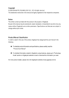
*
The WEEE marking on the product indicates this product must not be disposed of with user's other household waste
and must be handed over to a designated collection point for the recycling of waste electrical and electronic equipment!!
*
The WEEE marking applies only in European Union's member states.