Gigabyte GA-8I945GMF Manual
Gigabyte GA-8I945GMF Manual
 |
View all Gigabyte GA-8I945GMF manuals
Add to My Manuals
Save this manual to your list of manuals |
Gigabyte GA-8I945GMF manual content summary:
- Gigabyte GA-8I945GMF | Manual - Page 1
GA-8I945GMF Intel® Pentium® D / Pentium® 4 LGA775 Processor Motherboard User's Manual Rev. 1005 12ME-8I945GMF-1005R * The WEEE marking on the product indicates this product must not be disposed of with user's other household waste and must be handed over - Gigabyte GA-8I945GMF | Manual - Page 2
Motherboard GA-8I945GMF Apr. 26, 2005 Motherboard GA-8I945GMF Apr. 26, 2005 - Gigabyte GA-8I945GMF | Manual - Page 3
product information and specifications, please carefully read the "Product User Manual". „ For detailed information related to Gigabyte's unique features, please go to the "Technology Guide" section on Gigabyte's website to read or download the information you need. For more product details, please - Gigabyte GA-8I945GMF | Manual - Page 4
GA-8I945GMF Motherboard Layout 6 Block Diagram ...7 Chapter 1 Hardware Installation 9 1-1 Considerations Prior to Installation 9 1-2 Feature Summary 10 1-3 Installation of the CPU and Heatsink 12 1-3-1 Installation of the CPU 12 1-3-2 Installation of the Heatsink 13 1-4 Installation of Memory - Gigabyte GA-8I945GMF | Manual - Page 5
53 3-5 Contact Us ...53 Chapter 4 Appendix 55 4-1 Unique Software Utilities 55 4-1-1 EasyTune 5 Introduction 56 4-1-2 Xpress Recovery2 Introduction 57 4-1-3 Flash BIOS Method Introduction 60 4-1-4 2- / 4- / 6- / 8- Channel Audio Function Introduction 69 4-2 Troubleshooting 73 - 5 - - Gigabyte GA-8I945GMF | Manual - Page 6
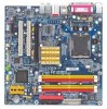
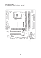
GA-8I945GMF Motherboard Layout COMA LPT KB_MS ATX_12V LGA775 CPU_FAN IT8712F RF_ID ATX VGA GA-8I945GMF USB USB 1394 LAN Intel 945G F_AUDIO AUDIO1 AUDIO2 PCIE_16 PCI1 Marvell 8053 PCI2 CD_IN PCIE_1 CODEC SPDIF_IO COMB DDRII1 DDRII2 DDRII3 DDRII4 IDE FDD BIOS SATAII2_3 ICH7 - Gigabyte GA-8I945GMF | Manual - Page 7
LGA775 Processor CPUCLK+/-(266/200/133MHz) Host Interface DDRII 667(Note)/533/400MHz DIMM Intel 945G GMCH Dual Channel Memory GMCHCLK (266/200/133MHz) 66MHz 33MHz 14.318MHz 48MHz BIOS ) To use a DDRII 667 memory module on the motherboard, you must install an 800/1066MHz FSB processor . - 7 - - Gigabyte GA-8I945GMF | Manual - Page 8
- 8 - - Gigabyte GA-8I945GMF | Manual - Page 9
instructions below: 1. Please turn off the computer and unplug its power cord. 2. When handling the motherboard , avoid touching any metal leads or connectors. 3. It is best to wear an electrostatic discharge (ESD) cuff when handling electronic components (CPU, RAM motherboard problem manual - Gigabyte GA-8I945GMF | Manual - Page 10
Pentium® D / Pentium® 4 LGA775 CPU(Note 1) Supports 1066/800/533MHz FSB L2 cache varies with CPU Northbridge: Intel® 945G Express chipset Southbridge: Intel® ICH7 Supported on the Win 2000/XP operating systems 4 DDRII DIMM memory slots (supports up to 4GB memory) (Note 2) Supports dual channel DDRII - Gigabyte GA-8I945GMF | Manual - Page 11
/ System fan failure warning Š CPU smart fan control Š System smart fan control BIOS Š Use of licensed AWARD BIOS Š Supports Q-Flash Additional Features Š Supports @BIOS Š Supports EasyTune5 (only supports Hardware Monitor function) Overclocking Š Over Clock via BIOS (DDRII) Form Factor - Gigabyte GA-8I945GMF | Manual - Page 12
- CPU: An Intel® Pentium 4 Processor with HT Technology - Chipset: An Intel® Chipset that supports HT Technology - BIOS: A BIOS that supports HT that might cause damage to the CPU during installation.) GA-8I945GMF Motherboard - 12 - Fig. 4 Once the CPU is properly inserted, please replace the - Gigabyte GA-8I945GMF | Manual - Page 13
the CPU and make sure the push pins aim to the pin hole on the motherboard.Pressing down the push pins diagonally. Fig. 4 Please make sure the Male and Female push pin are joined closely. (for detailed installation instructions, please refer to the heatsink installation section of the user manual - Gigabyte GA-8I945GMF | Manual - Page 14
fit in one direction. Insert the DIMM memory module vertically into the DIMM socket. Then push it down. Fig.2 Close the plastic clip at both edges of the DIMM sockets to lock the DIMM module. Reverse the installation steps when you wish to remove the DIMM module. GA-8I945GMF Motherboard - 14 - - Gigabyte GA-8I945GMF | Manual - Page 15
Channel DDR II GA-8I945GMF supports the Dual Channel Technology. After operating the Dual Channel Technology, the bandwidth of Memory Bus will double. GA-8I945GMF includes 4 DIMM sockets, and each Channel has two DIMM sockets as following: Channel A : DDR II 1, DDR II 2 Channel B : DDR II 3, DDR - Gigabyte GA-8I945GMF | Manual - Page 16
outlined below: 1. Read the related expansion card's instruction document before install the expansion card into the computer. the computer, if necessary, setup BIOS utility of expansion card from BIOS. 8. Install related driver from the operating system. Installing a GA-8I945GMF Motherboard - 16 - - Gigabyte GA-8I945GMF | Manual - Page 17
make sure your OS supports USB controller. If your OS does not support USB controller, please contact OS vendor for possible patch or driver upgrade. For more information please contact your OS or device(s) vendors. LAN Port The provided Internet connection is Gigabit Ethernet (PCI Express Gigabit - Gigabyte GA-8I945GMF | Manual - Page 18
the 2-/4-/6-/8- channel audio setup steps for detailed software configuration information. 1-7 Connectors Introduction 1 3 18 2 9 11 15 14 1) ATX_12V 2) ATX (Power Connector) 3) CPU_FAN 4) SYS_FAN 5) FDD 6) IDE 7) SATAII0_1 / SATAII2_3 8) F_PANEL 9) F_AUDIO GA-8I945GMF Motherboard 5 6 7 19 16 - Gigabyte GA-8I945GMF | Manual - Page 19
all components and devices are properly installed. Align the power connector with its proper location on the motherboard and connect tightly. The ATX_12V power connector mainly supplies power to the CPU. If the ATX_12V power connector is not connected, the system will not start. Caution! Please use - Gigabyte GA-8I945GMF | Manual - Page 20
the CPU fan to prevent CPU overheating and failure. 1 CPU_FAN 1 SYS_FAN Pin No. 1 2 3 4 Definition GND +12V Sense Speed Control ( drives supported are: 360KB, 720KB, 1.2MB, 1.44MB and 2.88MB. Please connect the red power connector wire to the pin1 position. 34 33 GA-8I945GMF Motherboard 2 1 - Gigabyte GA-8I945GMF | Manual - Page 21
refer to the instructions located on the IDE device). 40 39 2 1 7) SATAII0/SATAII1/SATAII2/SATAII3 (SATA 3Gb/s Connector) SATA 3Gb/s can provide up to 300MB/s transfer rate. Please refer to the BIOS setting for the Serial ATA and install the proper driver in order to work properly. Pin No - Gigabyte GA-8I945GMF | Manual - Page 22
1: Power Pin 2- Pin 3: NC Pin 4: Data(-) Open: Normal Close: Reset Hardware System Open: Normal Close: Power On/Off Pin 1: LED anode(+) Pin 2: LED cathode(-) NC GA-8I945GMF Motherboard - 22 - - Gigabyte GA-8I945GMF | Manual - Page 23
audio device unable to work or even damage it. For optional front panel audio module, please contact your chassis manufacturer. 10 9 2 1 HD Audio the audio driver is configured to support HD Audio. To connect an AC97 front panel audio module to this connector, please refer to the instructions on - Gigabyte GA-8I945GMF | Manual - Page 24
IN) Connect CD-ROM or DVD-ROM audio out to the connector. Pin No. and connector will make the device unable to work or even damage it. For optional front USB no standby power when system is off and it does not support USB device to wake up from S3 mode. Users who GA-8I945GMF Motherboard - 24 - - Gigabyte GA-8I945GMF | Manual - Page 25
pin assignment carefully while you connect the IEEE1394 cable, incorrect connection between the cable and connector will make the device unable to work or even damage it. For optional IEEE1394 cable, please contact your local dealer. Pin No. Definition 1 TPA+ 2 TPA- 2 10 3 GND 1 9 4 GND - Gigabyte GA-8I945GMF | Manual - Page 26
is capable of providing digital audio to external speakers or between the cable and connector will make the device unable to work or even damage it. For optional SPDIF_IO cable, please BIOS, if the system case begin remove. Pin No. Definition 1 1 Signal 2 GND GA-8I945GMF Motherboard - 26 - - Gigabyte GA-8I945GMF | Manual - Page 27
jumper. 1 Open: Normal 1 Short :Clear CMOS 18) RF_ID This connector allows you to connect external devices to use extra function. Check the pin assignments before you connect the external device cable. Please contact your nearest dealer for the optional GIGABYTE external device. Pin No. Definition - Gigabyte GA-8I945GMF | Manual - Page 28
type recommended by the manufacturer. Dispose of used batteries according to the manufacturer's instructions. If you want to erase CMOS... 1.Turn OFF the computer and unplug the power cord. 2. Take out the battery. 4.Plug the power cord and turn ON the computer. GA-8I945GMF Motherboard - 28 - - Gigabyte GA-8I945GMF | Manual - Page 29
to boot to DOS before upgrading BIOS but directly download and update BIOS from the Internet. CONTROL KEYS Enter> Move to select item Select Item Main Menu - Quit and not save changes into CMOS Status Page Setup Menu and Option - Gigabyte GA-8I945GMF | Manual - Page 30
BIOS when somehow the system works not stable as usual. This action makes the system reset to the default for stability. „ Standard CMOS voltage, fan, speed. „ Frequency / Voltage Control This setup page is control CPU clock and frequency ratio. „ Load Fail-Safe . GA-8I945GMF Motherboard - 30 - - Gigabyte GA-8I945GMF | Manual - Page 31
English „ Set User Password Change, set, or disable password. It allows you to limit access to the system. „ Save & Exit Setup Save CMOS value settings to CMOS and exit setup. „ Exit Without Saving Abandon all CMOS value changes and exit setup. - 31 - BIOS Setup - Gigabyte GA-8I945GMF | Manual - Page 32
CMOS Features Mon, Mar 28 2005 22:31:24 Item Help Menu Level` ` IDE Channel 0 Master ` IDE Channel 0 Slave [None] [None] Change the day, month, year Drive A Drive B Floppy 3 Mode Suport Holt On Base Memory Extended Memory Total Memory , 1 p.m. is 13:00:00. GA-8I945GMF Motherboard - 32 - - Gigabyte GA-8I945GMF | Manual - Page 33
for faster system start up. Manual User can manually input the correct settings Access Mode sided drive; 2.88M byte capacity. Floppy 3 Mode Support (for Japan Area) Disabled Normal Floppy Drive. (Default will be prompted. All Errors Whenever the BIOS detects a non-fatal error the system will - Gigabyte GA-8I945GMF | Manual - Page 34
on the motherboard, or 640K for systems with 640K or more memory installed on the motherboard. Extended Memory The BIOS determines how much extended memory is present during the POST. This is the amount of memory located above 1 MB in the CPU's memory address map. GA-8I945GMF Motherboard - 34 - Gigabyte GA-8I945GMF | Manual - Page 35
2-2 Advanced BIOS Features CMOS Setup Utility-Copyright (C) 1984-2005 Award Software Advanced BIOS Features ` Hard Disk Boot Priority First Boot Device Second Boot Device Third Boot Device Password Check # CPU Hyper-Threading Limit CPUID Max. to 3 No-Execute Memory Protect (Note) CPU Enhanced Halt - Gigabyte GA-8I945GMF | Manual - Page 36
is only working for operating system with multi processors mode supported. (Default value) Disables CPU Hyper Threading. Limit CPUID Max. to 3 Enabled Disabled Limit CPUID Maximum value to 3 when use older OS like NT4. Disables CPUID Limit for windows XP.(Default value) No-Execute Memory Protect - Gigabyte GA-8I945GMF | Manual - Page 37
Controller USB 2.0 Controller USB Keyboard Support USB Mouse Support Azalia Codec Onboard H/W 1394 Onboard H/W LAN Onboard LAN Values +/-/PU/PD: Value F10: Save F6: Fail-Save BIOS will auto detect. (Default value) Set On-Chip SATA mode to Combined, you can use up to 4 HDDs on the motherboard - Gigabyte GA-8I945GMF | Manual - Page 38
/IRQ7. (Default value) 278/IRQ5 3BC/IRQ7 Enable onboard LPT port and address is 278/IRQ5. Enable onboard LPT port and address is 3BC/IRQ7. GA-8I945GMF Motherboard - 38 - - Gigabyte GA-8I945GMF | Manual - Page 39
Parallel port as ECP & EPP mode. ECP Mode Use DMA 3 Set ECP Mode Use DMA to 3. (Default value) 1 Set ECP Mode Use DMA to 1. - 39 - BIOS Setup - Gigabyte GA-8I945GMF | Manual - Page 40
CMOS Level` KLJI: Move Enter: Select F5: Previous Values +/-/PU/PD: Value F10: Save F6: Fail-Save Default ESC: Exit F1: General Help F7: ) S3(STR) Set ACPI suspend type to S3/STR(Suspend To RAM). Soft-off by PWR-BTTN Instant-off Press power button then Power GA-8I945GMF Motherboard - 40 - - Gigabyte GA-8I945GMF | Manual - Page 41
system, the system will be in "Off" state. Full-On (Default value) When AC-power back to the system, the system always in "On" state. Memory When AC-power back to the system, the system will return to the Last state before AC-power off. - 41 - Gigabyte GA-8I945GMF | Manual - Page 42
CMOS Setup Utility-Copyright (C) 1984-2005 Award Software PnP/PCI Configurations PCI 1 IRQ Assignment PCI 2 IRQ Assignment [Auto] [Auto] Item Help Menu Level` KLJI: Move Enter: Select F5: Previous Values +/-/PU/PD: Value F10 3,4,5,7,9,10,11,12,14,15 to PCI 2. GA-8I945GMF Motherboard - 42 - - Gigabyte GA-8I945GMF | Manual - Page 43
Fail Warning CPU Smart FAN Control CPU Smart FAN Mode System Smart FAN Control [Disabled] Yes OK OK OK OK 30oC 38oC 4687 RPM 0 RPM [Disabled] [Disabled] [Disabled] [Disabled] [Enabled] [Auto] [Enabled] Item Help Menu Level` KLJI: Move Enter: Select F5: Previous Values +/-/PU/PD: Value F10: Save - Gigabyte GA-8I945GMF | Manual - Page 44
. With such CPU fans, selecting PWM will not effectively reduce the fan speed. System Smart FAN Control Disabled Disable this function. Enabled When this function is enabled, System fan will run at different speed depending on System temperature. (Default Value) GA-8I945GMF Motherboard - 44 - Gigabyte GA-8I945GMF | Manual - Page 45
2-7 Frequency/Voltage Control CMOS Setup Utility-Copyright (C) 1984-2005 Award Software Frequency/Voltage Control CPU Clock Ratio System Memory Multiplier Memory Frequency (Mhz) [16X] [Auto] 533 Item Help Menu Level` KLJI: Move Enter: Select F5: Previous Values +/-/PU/PD: Value F10: Save F6 - Gigabyte GA-8I945GMF | Manual - Page 46
Set User Password Load Optimized DefaultsS(aYve/N&)?ENxit Setup Exit Without Saving KLJI: Select Item F10: Save & Exit Setup Load Optimized Defaults Selecting this field loads the factory defaults for BIOS and Chipset Features which the system automatically detects. GA-8I945GMF Motherboard - 46 - - Gigabyte GA-8I945GMF | Manual - Page 47
Control Load Fail-Safe Defaults Load Optimized Defaults Set Supervisor Password Set User Password Save & Exit Setup Exit Without Saving ESC: Quit F8: Q-Flash KLJI: Select Item F10: Save & Exit Setup Change/Set/Disable Password Selecting this field loads the factory defaults for BIOS and Chipset - Gigabyte GA-8I945GMF | Manual - Page 48
Set Supervisor Password Set User Password Quit Without Saving (YSa/Nve)?&NExit Setup Exit Without Saving KLJI: Select Item F10: Save & Exit Setup Abandon all Data Type "Y" will quit the Setup Utility without saving to RTC CMOS. Type "N" will return to Setup Utility. GA-8I945GMF Motherboard - 48 - - Gigabyte GA-8I945GMF | Manual - Page 49
- 49 - BIOS Setup English - Gigabyte GA-8I945GMF | Manual - Page 50
English GA-8I945GMF Motherboard - 50 - - Gigabyte GA-8I945GMF | Manual - Page 51
shown in Windows XP. Insert the driver CD-title that came with your motherboard into your CD-ROM drive, the driver CD-title will auto start and show the installation guide. If not, please double click the CD-ROM device icon in "My computer", and execute the Run.exe. 3-1 Install Chipset Drivers After - Gigabyte GA-8I945GMF | Manual - Page 52
Software Applications This page displays all the tools that Gigabyte developed and some free software, you can choose anyone you want and press "install" to install them. 3-3 Driver CD Information This page lists the contents of software and drivers in this CD-title. GA-8I945GMF Motherboard - 52 - - Gigabyte GA-8I945GMF | Manual - Page 53
English 3-4 Hardware Information This page lists all device you have for this motherboard. 3-5 Contact Us Please see the last page for details. - 53 - Install Drivers - Gigabyte GA-8I945GMF | Manual - Page 54
English GA-8I945GMF Motherboard - 54 - - Gigabyte GA-8I945GMF | Manual - Page 55
the "Clear CMOS" pins or the battery on the motherboard to reset the system back to factory default settings. Instead, S.O.S. automatically resets the overclocked system settings back to their factory defaults to provide a more user-friendly and reliable platform for users. Download Center Download - Gigabyte GA-8I945GMF | Manual - Page 56
yet easy to use tools such as 1) Overclocking for enhancing system performance, 2) C.I.A. and M.I.B. for special enhancement for CPU and Memory, 3) Smart-Fan control for managing fan speed control of both CPU cooling fan and North-Bridge Chipset cooling fan, 4) PC health for monitoring system - Gigabyte GA-8I945GMF | Manual - Page 57
and restoration of hard disk data. Supporting Microsoft operating systems including Windows XP/2000/NT/98/Me and DOS, and file systems including FAT16, FAT32, and NTFS, Xpress Recovery2 is able to back up data on hard disks on PATA and SATA IDE controllers. After Xpress Recovery2 is executed from - Gigabyte GA-8I945GMF | Manual - Page 58
Windows 2000, be sure to execute the EnableBigLba.exe program from the driver CD before data backup. 2. It is normal that data backup takes longer time than data restoration. 3. Xpress Recovery2 is compliant with the GPL regulations. 4. On a few motherboards based on Nvidia chipsets, BIOS update - Gigabyte GA-8I945GMF | Manual - Page 59
refer to Part Two. Part One: Updating BIOS with Q-FlashTM Utility on Dual BIOS Motherboards. Some of Gigabyte motherboards are equipped with dual BIOS. In the BIOS menu of the motherboards supporting Q-Flash and Dual BIOS, the Q-Flash utility and Dual BIOS utility are combined in the same screen - Gigabyte GA-8I945GMF | Manual - Page 60
pressing Enter key on your keyboard to enable execution of the task. Action bar: Contains the names of four actions needed to operate the Q-Flash/Dual BIOS utility. Pressing the buttons mentioned on your keyboards to perform these actions. GA-8I945GMF Motherboard - 60 - - Gigabyte GA-8I945GMF | Manual - Page 61
flash and press Enter. In this example, we only download one BIOS file to the floppy disk so only one BIOS file, 8KNXPU.Fba, is listed. Please confirm again you have the correct BIOS file for your motherboard. Dual BIOS Utility Boot From Main Bios Main ROM Type/Size SST 49LF003A Backup ROM Type - Gigabyte GA-8I945GMF | Manual - Page 62
Channel Primary Master : FUJITSU MPE3170AT ED-03-08 Primary Slave : None Secondary Master : CREATIVEDVD-RM DVD1242E BC101 Secondary Slave : None Press DEL to enter SETUP / Dual BIOS / Q-Flash / F9 For Xpress Recovery 09/23/2003-i875P-6A79BG03C-00 GA-8I945GMF Motherboard - 62 - - Gigabyte GA-8I945GMF | Manual - Page 63
F8: Dual BIOS/Q-Flash F3: Change Language F10: Save & Exit Setup Time, Date, Hard Disk Type... Press Y on your keyboard to save and exit. Part Two: Updating BIOS with Q-FlashTM Utility on Single-BIOS Motherboards. This part guides users of single-BIOS motherboards how to update BIOS using the - Gigabyte GA-8I945GMF | Manual - Page 64
ReseEt SyCs:tRemeset F10:Power Off Do not trun off power or reset your system at this stage!! After BIOS file is read, you'll see a confirmation dialog box asking you "Are you sure to update BIOS?" Please do not take out the floppy disk when it begins flashing BIOS. GA-8I945GMF Motherboard - 64 - Gigabyte GA-8I945GMF | Manual - Page 65
file becomes F4 after updating Award Modular BIOS v6.00PG, An Energy Star Ally Copyright (C) 1984-2003, Award Software, Inc. Intel 845GE AGPSet BIOS for 8GE800 F4 Check System Health OK Main Processor : Intel Pentium(R) 4 1.7GHz (100x17.0) Memory Testing : 122880K OK - Gigabyte GA-8I945GMF | Manual - Page 66
Update" icon b. Click "Update New BIOS" c. Please select "All Files" in dialog box while opening the old file. d. Please search for BIOS unzip file, downloading from internet or any other methods (such as: 8I945GMF.F2). e. Complete update process following the instruction. GA-8I945GMF Motherboard - Gigabyte GA-8I945GMF | Manual - Page 67
II, be sure that motherboard's model name in BIOS unzip file are the same as your motherboard's. Otherwise, your system won't boot. III. In method I, if the BIOS file you need cannot be found in @BIOSTM server, please go onto Gigabyte's web site for downloading and updating it according to method - Gigabyte GA-8I945GMF | Manual - Page 68
driver, you should find an Audio Manager icon in your system tray (you can also find the icon in Control Panel). Double-click the icon to open the Audio Control Panel. STEP 2: In the Audio Control Panel, click the Audio I/O tab. In the upper left list, click 2CH Speaker. GA-8I945GMF Motherboard - Gigabyte GA-8I945GMF | Manual - Page 69
Panel). Double-click the icon to open the Audio Control Panel. STEP 2: In the Audio Control Panel, click the Audio I/O tab. In the upper left list, click 4CH Speaker. STEP 3: After plugging in 4-channel speakers to the rear speaker jacks, a small window will pop up and ask you what type of equipment - Gigabyte GA-8I945GMF | Manual - Page 70
6-channel audio setup is completed. 8 Channel Audio Setup STEP 1 : After installation of the audio driver, you should find an Audio Manager icon in your system tray (you can also find the icon in Control Panel). Double-click the icon to open the Audio Control Panel. GA-8I945GMF Motherboard - 70 - Gigabyte GA-8I945GMF | Manual - Page 71
STEP 2: In the Audio Control Panel, click the Audio I/O tab. In the upper left list, click 8CH Speaker. STEP 3: After plugging in 8-channel speakers to the rear speaker jacks, a small window will pop up and ask you what type of equipment is connected. Choose a device depending on the type of speaker - Gigabyte GA-8I945GMF | Manual - Page 72
or display card error 1 long 3 short: Keyboard error 9 beeps ROM checksum error 1 long 9 short: BIOS ROM error 10 beeps CMOS shutdown register read/write error Continuous long beeps: DRAM error 11 beeps Cache memory bad Continuous short beeps: Power error GA-8I945GMF Motherboard - 72 - - Gigabyte GA-8I945GMF | Manual - Page 73
- 73 - Appendix English - Gigabyte GA-8I945GMF | Manual - Page 74
English GA-8I945GMF Motherboard - 74 - - Gigabyte GA-8I945GMF | Manual - Page 75
- 75 - Appendix English - Gigabyte GA-8I945GMF | Manual - Page 76
English GA-8I945GMF Motherboard - 76 - - Gigabyte GA-8I945GMF | Manual - Page 77
- 77 - Appendix English - Gigabyte GA-8I945GMF | Manual - Page 78
English GA-8I945GMF Motherboard - 78 - - Gigabyte GA-8I945GMF | Manual - Page 79
.giga-byte.com U.S.A. G.B.T. INC. TEL: +1-626-854-9338 FAX: +1-626-854-9339 Tech. Support : http://tw.giga-byte.com/TechSupport/ServiceCenter.htm Non-Tech. Support(Sales/Marketing) : http://ggts.gigabyte.com.tw/nontech.asp WEB address : http://www.giga-byte.com Germany G.B.T. TECHNOLOGY TRADING GMBH - Gigabyte GA-8I945GMF | Manual - Page 80
.gigabyte.cz Romania Representative Office Of GIGA-BYTE Technology Co., Ltd. in Romania Tech. Support : http://tw.giga-byte.com/TechSupport/ServiceCenter.htm Non-Tech. Support(Sales/Marketing) : http://ggts.gigabyte.com.tw/nontech.asp WEB address: http://www.gigabyte.com.ro GA-8I945GMF Motherboard
-
 1
1 -
 2
2 -
 3
3 -
 4
4 -
 5
5 -
 6
6 -
 7
7 -
8
-
9
-
10
-
11
-
12
-
13
-
14
-
15
-
16
-
17
-
18
-
19
-
20
-
21
-
22
-
23
-
24
-
25
-
26
-
27
-
28
-
29
-
30
-
31
-
32
-
33
-
34
-
35
-
36
-
37
-
38
-
39
-
40
-
41
-
42
-
43
-
44
-
45
-
46
-
47
-
48
-
49
-
50
-
51
-
52
-
53
-
54
-
55
-
56
-
57
-
58
-
59
-
60
-
61
-
62
-
63
-
64
-
65
-
66
-
67
-
68
-
69
-
70
-
71
-
72
-
73
-
74
-
75
-
76
-
77
-
78
-
79
-
80
 |
 |

GA-8I945GMF
Intel
®
Pentium
®
D / Pentium
®
4 LGA775 Processor Motherboard
User's Manual
Rev. 1005
12ME-8I945GMF-1005R
*
The WEEE marking on the product indicates this product must not be disposed of with user's other household waste
and must be handed over to a designated collection point for the recycling of waste electrical and electronic equipment!!
*
The WEEE marking applies only in European Union's member states.