Gigabyte GA-8I945GMH-RH Manual
Gigabyte GA-8I945GMH-RH Manual
 |
View all Gigabyte GA-8I945GMH-RH manuals
Add to My Manuals
Save this manual to your list of manuals |
Gigabyte GA-8I945GMH-RH manual content summary:
- Gigabyte GA-8I945GMH-RH | Manual - Page 1
GA-8I945GMH-RH Intel® Pentium® Processor Extreme Edition Intel® Pentium® D / Pentium® 4 LGA775 Processor Motherboard User's Manual Rev. 1001 12ME-945GMHR-1001R * The WEEE marking on the product indicates this product must not be disposed of with user's other household waste and must - Gigabyte GA-8I945GMH-RH | Manual - Page 2
Motherboard GA-8I945GMH-RH Jan. 20, 2006 Motherboard GA-8I945GMH-RH Jan. 20, 2006 - Gigabyte GA-8I945GMH-RH | Manual - Page 3
in the following: „ For detailed product information and specifications, please carefully read the "Product User Manual". „ For detailed information related to Gigabyte's unique features, please go to "Technology Guide" section on Gigabyte's website to read or download the information you need - Gigabyte GA-8I945GMH-RH | Manual - Page 4
Table of Contents GA-8I945GMH-RH Motherboard Layout 6 Block Diagram ...7 Chapter 1 Hardware Installation 9 1-1 Considerations Prior to Installation 9 1-2 Feature Summary 10 1-3 Installation of the CPU and Heatsink 12 1-3-1 Installation of the CPU 12 1-3-2 Installation of the Heatsink 13 1-4 - Gigabyte GA-8I945GMH-RH | Manual - Page 5
5 Introduction 54 4-1-2 Xpress Recovery2 Introduction 55 4-1-3 Flash BIOS Method Introduction 57 4-1-4 Configuring SATA Hard Drive(s) (Controller: Intel ICH7-DH 66 (4) Making a SATA Driver Disk 73 4-1-5 2- / 4- / 6- / 8- Channel Audio Function Introduction 77 4-2 Troubleshooting 81 - 5 - - Gigabyte GA-8I945GMH-RH | Manual - Page 6
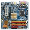
GA-8I945GMH-RH Motherboard Layout KB_MS SPDIF_O SPDIF_I ATX_12V LPT VGA LGA775 CPU_FAN GA-8I945GMH-RH ATX IT8712F 1394 USB LAN USB AUDIO1 AUDIO2 F_AUDIO PCIE_16 Intel 945G IDE DDRII1 DDRII2 DDRII3 DDRII4 Vidalia PCI1 82573L PCI2 CD_IN PCIE_1 CI CODEC COMA F1_1394 ICH7-DH - Gigabyte GA-8I945GMH-RH | Manual - Page 7
DIMM Intel 945G GMCH Dual Channel Memory GMCHCLK (266/200/133MHz) 66MHz 33MHz 14.318MHz 48MHz BIOS Intel ICH7-DH 4 Serial ATAII ATA33/66/100 IDE Channels Floppy IT 8712F LPT Port COM To use a DDRII 667 memory module on the motherboard, you must install an 800/1066MHz FSB processor . - 7 - - Gigabyte GA-8I945GMH-RH | Manual - Page 8
- 8 - - Gigabyte GA-8I945GMH-RH | Manual - Page 9
instructions below: 1. Please turn off the computer and unplug its power cord. 2. When handling the motherboard , avoid touching any metal leads or connectors. 3. It is best to wear an electrostatic discharge (ESD) cuff when handling electronic components (CPU motherboard problem manual - Gigabyte GA-8I945GMH-RH | Manual - Page 10
Š 1 front panel connector Š 1 front audio connector Š 1 CD In connector Š 1 COMA connector Š 2 USB 2.0/1.1 connectors for additional 4 ports by cables Š 2 IEEE1394a connectors for additional 2 ports by cables Š 1 CI connector Š 1 power LED connector GA-8I945GMH-RH Motherboard - 10 - - Gigabyte GA-8I945GMH-RH | Manual - Page 11
4 USB 2.0/1.1 ports Š 1 1394 port Š 1 RJ-45 port (LAN) Š 6 audio jacks (Line In / Line Out / MIC In / Surround Speaker Out 4cm (Note 1) For further CPU support information, please go to GIGABYTE's website. (Note 2) Due module on the motherboard, you must install an 800/1066MHz FSB processor - Gigabyte GA-8I945GMH-RH | Manual - Page 12
- CPU: An Intel® Pentium 4 Processor with HT Technology - Chipset: An Intel® Chipset that supports HT Technology - BIOS: A BIOS that supports HT that might cause damage to the CPU during installation.) GA-8I945GMH-RH Motherboard - 12 - Fig. 4 Once the CPU is properly inserted, please replace the - Gigabyte GA-8I945GMH-RH | Manual - Page 13
the CPU and make sure the push pins aim to the pin hole on the motherboard.Pressing down the push pins diagonally. Fig. 4 Please make sure the Male and Female push pin are joined closely. (for detailed installation instructions, please refer to the heatsink installation section of the user manual - Gigabyte GA-8I945GMH-RH | Manual - Page 14
insert the module, please switch the direction. The motherboard supports DDR II memory modules, whereby BIOS will automatically detect memory capacity and specifications. Memory modules are designed so that they can steps when you wish to remove the DIMM module. GA-8I945GMH-RH Motherboard - 14 - - Gigabyte GA-8I945GMH-RH | Manual - Page 15
GA-8I945GMH-RH includes 4 DIMM sockets, and each Channel has two DIMM sockets as following: Channel A : DDR II 1, DDR II 2 Channel B : DDR II 3, DDR II 4 If you want to operate the Dual Channel Technology, please note the following explanations due to the limitation of Intel chipset specifications - Gigabyte GA-8I945GMH-RH | Manual - Page 16
outlined below: 1. Read the related expansion card's instruction document before install the expansion card into the computer the computer, if necessary, setup BIOS utility of expansion card from BIOS. 8. Install related driver from the operating system. Installing GA-8I945GMH-RH Motherboard - 16 - - Gigabyte GA-8I945GMH-RH | Manual - Page 17
port is capable of providing digital audio to external speakers or compressed AC3 supports USB controller. If your OS does not support USB controller, please contact OS vendor for possible patch or driver local dealer.) LAN Port The provided Internet connection is Gigabit Ethernet, providing data - Gigabyte GA-8I945GMH-RH | Manual - Page 18
In addition to the default speakers settings, the ~ audio jacks can be reconfigured to perform different functions via the audio software. Only microphones still MUST be connected to the default 13) F1_1394 / F2_1394 14) COMA 15) CI 16) CLR_CMOS 17) BATTERY GA-8I945GMH-RH Motherboard - 18 - - Gigabyte GA-8I945GMH-RH | Manual - Page 19
all components and devices are properly installed. Align the power connector with its proper location on the motherboard and connect tightly. The ATX_12V power connector mainly supplies power to the CPU. If the ATX_12V power connector is not connected, the system will not start. Caution! Please use - Gigabyte GA-8I945GMH-RH | Manual - Page 20
. Caution! Please remember to connect the power to the CPU fan to prevent CPU overheating and failure. 1 CPU_FAN 1 SYS_FAN Pin No. supported are: 360KB, 720KB, 1.2MB, 1.44MB and 2.88MB. Please connect the red power connector wire to the pin1 position. 34 33 2 1 GA-8I945GMH-RH Motherboard - Gigabyte GA-8I945GMH-RH | Manual - Page 21
, please refer to the instructions located on the IDE device). 40 39 2 1 7) SATAII0/SATAII1/SATAII2/SATAII3 (SATA 3Gb/s Connector) SATA 3Gb/s can provide up to 300MB/s transfer rate. Please refer to the BIOS setting for the Serial ATA and install the proper driver in order to work properly - Gigabyte GA-8I945GMH-RH | Manual - Page 22
1: Power Pin 2- Pin 3: NC Pin 4: Data(-) Open: Normal Close: Reset Hardware System Open: Normal Close: Power On/Off Pin 1: LED anode(+) Pin 2: LED cathode(-) NC GA-8I945GMH-RH Motherboard - 22 - - Gigabyte GA-8I945GMH-RH | Manual - Page 23
Line Out (R) 6 NC 7 NC 8 No Pin 9 Line Out (L) 10 NC By default, the audio driver is configured to support HD Audio. To connect an AC97 front panel audio module to this connector, please refer to the instructions on Page 77 about the software settings. 10) PWR_LED PWR_LED is connect with - Gigabyte GA-8I945GMH-RH | Manual - Page 24
English 11) CD_IN (CD IN) Connect CD-ROM or DVD-ROM audio out to the connector. 1 Pin No. Definition 1 CD-L 2 GND 3 GND 4 CD -R 12) F_ USB / 2 Power (5V) 2 10 3 USB DX- 1 9 4 USB Dy- 5 USB DX+ 6 USB Dy+ 7 GND 8 GND 9 No Pin 10 NC GA-8I945GMH-RH Motherboard - 24 - - Gigabyte GA-8I945GMH-RH | Manual - Page 25
English 13) F1_1394 / F2_1394 (IEEE 1394 Connector) Serial interface standard set by Institute of Electrical and Electronics Engineers, which has features like high speed, highbandwidth and hot plug. Be careful with the polarity of the IEEE1394 connector. Check the pin assignment carefully while - Gigabyte GA-8I945GMH-RH | Manual - Page 26
Case Open) This 2-pin connector allows your system to enable or disable the "Case Open" item in BIOS, if the system case begin remove. Pin No. Definition 1 1 Signal 2 GND 16) CLR_CMOS ( from improper use this jumper. 1 Open: Normal 1 Short: Clear CMOS GA-8I945GMH-RH Motherboard - 26 - - Gigabyte GA-8I945GMH-RH | Manual - Page 27
is incorrectly replaced. Replace only with the same or equivalent type recommended by the manufacturer. Dispose of used batteries according to the manufacturer's instructions. If you want to erase CMOS... 1.Turn OFF the computer and unplug the power cord. 2. Take out the battery gently and put it - Gigabyte GA-8I945GMH-RH | Manual - Page 28
English GA-8I945GMH-RH Motherboard - 28 - - Gigabyte GA-8I945GMH-RH | Manual - Page 29
the first time, it is recommended that you save the current BIOS to a disk in the event that BIOS needs to be reset to its original settings. If you wish to upgrade to a new BIOS, either Gigabyte's Q-Flash or @BIOS utility can be used. Q-Flash allows the user to quickly and easily update or backup - Gigabyte GA-8I945GMH-RH | Manual - Page 30
in the BIOS when somehow the system works not stable as usual. This action makes the system reset to the default for stability. The BIOS Setup menus described in this chapter are for reference only and may differ from the exact settings for your motherboard. GA-8I945GMH-RH Motherboard - 30 - Gigabyte GA-8I945GMH-RH | Manual - Page 31
setup page includes all the items in standard compatible BIOS. „ Advanced BIOS Features This setup page includes all the items of voltage, fan, speed. „ Frequency / Voltage Control This setup page is control CPU clock and frequency ratio. „ Load Fail-Safe Defaults Fail-Safe Defaults indicates the - Gigabyte GA-8I945GMH-RH | Manual - Page 32
>, . Week The week, from Sun to Sat, determined by the BIOS and is display only Month The month, Jan. Through Dec. Day The will skip the automatic Manual detection step and allow for faster system start up. User can manually input the correct settings GA-8I945GMH-RH Motherboard - 32 - - Gigabyte GA-8I945GMH-RH | Manual - Page 33
88M byte capacity. Floppy 3 Mode Support (for Japan Area) Disabled Normal be prompted. Whenever the BIOS detects a non-fatal error the BIOS. Base Memory The POST of the BIOS will motherboard, or 640K for systems with 640K or more memory installed on the motherboard. Extended Memory The BIOS - Gigabyte GA-8I945GMH-RH | Manual - Page 34
access to Setup page if the correct password is not entered at the prompt. (Note) This item will show up when you install a processor which supports this function. GA-8I945GMH-RH Motherboard - 34 - - Gigabyte GA-8I945GMH-RH | Manual - Page 35
that this feature is only working for operating system with multi processors mode supported. (Default value) Disables CPU Hyper Threading. Limit CPUID Max. to 3 Enabled Disabled Limit CPUID Maximum item will show up when you install a processor which supports this function. - 35 - BIOS Setup - Gigabyte GA-8I945GMH-RH | Manual - Page 36
) Ch.0 Master/Slave Set PATA IDE to Ch. 0 Master/Slave. SATA Port 0/2 Set to This value will auto make by the setting "On-Chip SATA Mode" and "PATA IDE Set to". If PATA IDE were set to Ch. 1 Master/Slave, this function will auto set to Ch. 0 Master/Slave. GA-8I945GMH-RH Motherboard - 36 - - Gigabyte GA-8I945GMH-RH | Manual - Page 37
Boot ROM This function decide whether to invoke the boot ROM of the onboard LAN chip. Enabled Disabled Enable this function. Disable this function. (Default value) Onboard Serial Port 1 Auto 3F8/IRQ4 BIOS will automatically setup the port 1 address. Enable onboard Serial port 1 and address is - Gigabyte GA-8I945GMH-RH | Manual - Page 38
Using Parallel port as ECP & EPP mode. ECP Mode Use DMA 3 Set ECP Mode Use DMA to 3. (Default value) 1 Set ECP Mode Use DMA to 1. GA-8I945GMH-RH Motherboard - 38 - - Gigabyte GA-8I945GMH-RH | Manual - Page 39
system. If RTC Alarm Lead To Power On is Enabled. Date (of Month) Alarm : Everyday, 1~31 Time (hh: mm: ss) Alarm : (0~23) : (0~59) : (0~59) - 39 - BIOS Setup - Gigabyte GA-8I945GMH-RH | Manual - Page 40
) Set IRQ 3,4,5,7,9,10,11,12,14,15 to PCI 1. Auto assign IRQ to PCI 2. (Default value) Set IRQ 3,4,5,7,9,10,11,12,14,15 to PCI 2. GA-8I945GMH-RH Motherboard - 40 - - Gigabyte GA-8I945GMH-RH | Manual - Page 41
158oF. Monitor CPU temperature at 80oC / 176oF. 90oC / 194oF Monitor CPU temperature at 90oC / 194oF. Disabled Disable this function. (Default value) CPU / System FAN Fail Warning Disabled Fan warning function disable. (Default value) Enabled Fan warning function enable. - 41 - BIOS Setup - Gigabyte GA-8I945GMH-RH | Manual - Page 42
option can be used for CPU fans with 3-pin or 4-pin power cables. However, some 4-pin CPU fan power cables are not designed following Intel 4-Wire fans PWM control specifications. With such CPU fans, selecting PWM will not effectively reduce the fan speed. GA-8I945GMH-RH Motherboard - 42 - - Gigabyte GA-8I945GMH-RH | Manual - Page 43
Auto Set Memory frequency by DRAM SPD data. (Default value) Memory Frequency (Mhz) The values depend on "System Memory Multiplier" item. Normal CPU Vcore Display your CPU's normal voltage. (Note) This item will show up when you install a processor which supports this function. - 43 - BIOS Setup - Gigabyte GA-8I945GMH-RH | Manual - Page 44
Copyright (C) 1984-2005 Award Software ` Standard CMOS Features ` Advanced BIOS Features ` Integrated Peripherals ` Power Management Setup ` PnP/PCI field loads the factory defaults for BIOS and Chipset Features which the system automatically detects. GA-8I945GMH-RH Motherboard - 44 - - Gigabyte GA-8I945GMH-RH | Manual - Page 45
Quit F8: Q-Flash KLJI: Select Item F10: Save & Exit Setup Change/Set/Disable Password Selecting this field loads the factory defaults for BIOS and Chipset Features which the system automatically detects. When you select this function, the following message will appear at the center of the screen - Gigabyte GA-8I945GMH-RH | Manual - Page 46
CMOS Setup Utility-Copyright (C) 1984-2005 Award Software ` Standard CMOS Features ` Advanced BIOS Features ` Integrated Peripherals ` Power Management Setup ` PnP/PCI Configurations ` PC Health Status saving to RTC CMOS. Type "N" will return to Setup Utility. GA-8I945GMH-RH Motherboard - 46 - - Gigabyte GA-8I945GMH-RH | Manual - Page 47
- 47 - BIOS Setup English - Gigabyte GA-8I945GMH-RH | Manual - Page 48
English GA-8I945GMH-RH Motherboard - 48 - - Gigabyte GA-8I945GMH-RH | Manual - Page 49
that came with your motherboard into your CD-ROM drive, the driver CD-title will auto start and show the installation guide. If not, please double click the CD-ROM device icon in "My computer", and execute the Run.exe. 3-1 Install Chipset Drivers After insert the driver CD, "Xpress Install" will - Gigabyte GA-8I945GMH-RH | Manual - Page 50
Applications This page displays all the tools that Gigabyte developed and some free software, you can choose anyone you want and press "install" to install them. 3-3 Driver CD Information This page lists the contents of software and drivers in this CD-title. GA-8I945GMH-RH Motherboard - 50 - - Gigabyte GA-8I945GMH-RH | Manual - Page 51
English 3-4 Hardware Information This page lists all device you have for this motherboard. 3-5 Contact Us Please see the last page for details. - 51 - Install Drivers - Gigabyte GA-8I945GMH-RH | Manual - Page 52
English GA-8I945GMH-RH Motherboard - 52 - - Gigabyte GA-8I945GMH-RH | Manual - Page 53
) Motherboard Intelligent Tweaker (M.I.T.) allows user to access and change BIOS feature settings with relative speed and ease. Through GIGABYTE M.I.T. feature the user is no longer required to switch into different modes within BIOS setup in order to change system settings such as the CPU system - Gigabyte GA-8I945GMH-RH | Manual - Page 54
the current functions status 9. GIGABYTE Logo Log on to GIGABYTE website 10. Help button Display EasyTuneTM 5 Help file 11. Exit or Minimize button Quit or Minimize EasyTuneTM 5 software (Note) EasyTune 5 functions may vary depending on different motherboards. GA-8I945GMF Motherboard - 54 - - Gigabyte GA-8I945GMH-RH | Manual - Page 55
data on hard disks on PATA and SATA IDE controllers. After Xpress Recovery2 is executed 64M bytes of system memory 3. VESA-supported VGA cards How to use the BIOS Setup, go to Advanced BIOS Feature and set to boot from CD-ROM. Save the settings and exit the BIOS Setup. Insert the provided driver - Gigabyte GA-8I945GMH-RH | Manual - Page 56
RAID and SATA IDE mode. Please contact your motherboard manufacturer. 5. Xpress Recovery2 supports only PATA hard disks and not SATA hard disks on the following motherboards (As this is a BIOS-related issue, it can be solved by BIOS update) GA-K8U GA-K8U-9 GA-K8NXP-SLI GA-K8N Ultra-SLI GA - Gigabyte GA-8I945GMH-RH | Manual - Page 57
of Gigabyte motherboards are equipped with dual BIOS. In the BIOS menu of the motherboards supporting Q-Flash and Dual BIOS, the Q-Flash utility and Dual BIOS utility are combined in the same screen. This section only deals with how to use Q-Flash utility. In the following sections, we take GA-8KNXP - Gigabyte GA-8I945GMH-RH | Manual - Page 58
Enter key on your keyboard to enable execution of the task. Action bar: Contains the names of four actions needed to operate the Q-Flash/Dual BIOS utility. Pressing the buttons mentioned on your keyboards to perform these actions. GA-8I945GMF Motherboard - 58 - - Gigabyte GA-8I945GMH-RH | Manual - Page 59
using the Q-Flash utility. As described in the "Before you begin" section above, you must prepare a floppy disk having the BIOS file for your motherboard and insert it to your computer. If you have already put the floppy disk into your system and have entered the Q-Flash utility, please follow - Gigabyte GA-8I945GMH-RH | Manual - Page 60
Primary Master : FUJITSU MPE3170AT ED-03-08 Primary Slave : None Secondary Master : CREATIVEDVD-RM DVD1242E BC101 Secondary Slave : None Press DEL to enter SETUP / Dual BIOS / Q-Flash / F9 For Xpress Recovery 09/23/2003-i875P-6A79BG03C-00 GA-8I945GMF Motherboard - 60 - - Gigabyte GA-8I945GMH-RH | Manual - Page 61
Type... Press Y on your keyboard to save and exit. Part Two: Updating BIOS with Q-FlashTM Utility on Single-BIOS Motherboards. This part guides users of single-BIOS motherboards how to update BIOS using the Q-FlashTM utility. CMOS Setup Utility-Copyright (C) 1984-2004 Award Software ` Standard - Gigabyte GA-8I945GMH-RH | Manual - Page 62
to flash and press Enter. In this example, we only download one BIOS file to the floppy disk so only one BIOS file, 8GE800.F4, is listed. Please confirm again you have the correct BIOS file for your motherboard. Q-Flash Utility V1.30 Flash Type/Size SST 49LF003A 256K 8GE800.F4Keep DMI1Dfialeta - Gigabyte GA-8I945GMH-RH | Manual - Page 63
oErS[CE:sRce]steot abort..F. 10:Power Off After system reboots, you may find the BIOS version on your boot screen becomes the one you flashed. The BIOS file becomes F4 after updating Award Modular BIOS v6.00PG, An Energy Star Ally Copyright (C) 1984-2003, Award Software, Inc. Intel 845GE AGPSet - Gigabyte GA-8I945GMH-RH | Manual - Page 64
icon b. Click "Update New BIOS" c. Please select "All Files" in dialog box while opening the old file. d. Please search for BIOS unzip file, downloading from internet or any other methods (such as: 8I945GMHRH.E7). e. Complete update process following the instruction. GA-8I945GMF Motherboard - 64 - - Gigabyte GA-8I945GMH-RH | Manual - Page 65
. II. In method II, be sure that motherboard's model name in BIOS unzip file are the same as your motherboard's. Otherwise, your system won't boot. III. In method I, if the BIOS file you need cannot be found in @BIOSTM server, please go onto Gigabyte's web site for downloading and updating it - Gigabyte GA-8I945GMH-RH | Manual - Page 66
to the rear of the SATA hard drive and the other end to available SATA 3Gb/s port(s) on the motherboard. Then connect the power connector from your power supply to the hard drive. "*" Skip this step if you do not want to create RAID array on the SATA controller GA-8I945GMH-RH Motherboard - 66 - - Gigabyte GA-8I945GMH-RH | Manual - Page 67
1: Turn on your computer and press Del to enter BIOS Setup during POST (Power-On Self Test). If you want to create RAID, set SATA RAID/AHCI Mode under the Integrated Peripherals menu to RAID (Disabled by default). Then, set On-Chip SATA Mode to Manual or Auto (default) based on your own requirements - Gigabyte GA-8I945GMH-RH | Manual - Page 68
Disk Boot Priority under the Advanced BIOS Features menu. In the Hard Disk Boot Priority submenu, select the model of the SATA hard drive onto which you Defaults Figure 3 Step 4: Save and exit BIOS Setup. ESC: Exit F1: General Help F7: Optimized Defaults GA-8I945GMH-RH Motherboard - 68 - - Gigabyte GA-8I945GMH-RH | Manual - Page 69
BIOS setup utility. Intel(R) Matrix Storage Manager option ROM V5.0.0.1032 ICH7R wRAID5 Copyright(C) 2003-05 Intel Corporation. All Rights Reversed. RAID Volumes : None Defined. Physical Disks : Port Driver Model 0 ST3120026AS 1 ST3120026AS Serial # 3JT354CP 3JT329JX Size Type/Status(Vol - Gigabyte GA-8I945GMH-RH | Manual - Page 70
RAID_Volume0 RAID Level : RAID0(Stripe) Disks : Strip Size : Capacity : Select Disks 128KB 223.6 GB Create Volume [ HELP ] The following are typical values: RAID0 - 128KB RAID10 - 64KB RAID5 - 64KB [ ]-Change [TAB]-Next [ESC]-Previous Menu Figure 7 [ENTER]-Select GA-8I945GMH-RH Motherboard - Gigabyte GA-8I945GMH-RH | Manual - Page 71
English Step 5: After setting all the items above, select Create Volume and press ENTER (Figure 8) to begin the creation of the RAID array. Intel(R) Matrix Storage Manager option ROM V5.0.0.1032 ICH7R wRAID5 Copyright(C) 2003-05 Intel Corporation. All Rights Reversed. [ CREATE VOLUME MENU ] Name - Gigabyte GA-8I945GMH-RH | Manual - Page 72
RAID Volume If you want to delete a RAID volume, select the Delete RAID Volume option in Main Menu. Press ENTER and follow on-screen instructions RAID BIOS utility, press ESC in Main Menu. Now, you can proceed to the installation of the SATA driver and operating system. GA-8I945GMH-RH Motherboard - Gigabyte GA-8I945GMH-RH | Manual - Page 73
driver for the SATA controller from the motherboard driver CD-ROM to a floppy disk. See the instructions below about how to copy the driver in MS-DOS mode(Note1). Prepare a startup disk that has CD-ROM support an alternative system and insert the GIGABYTE motherboard driver CD-ROM. From the CD-ROM - Gigabyte GA-8I945GMH-RH | Manual - Page 74
manufacturer, press S. * If you do not have any device support disks from a mass storage device manufacturer, or do not want to specify additional mass storage devices for use with Windows, press ENTER. S=Specify Additional Device ENTER=Continue F3=Exit Figure 16 GA-8I945GMH-RH Motherboard - 74 - - Gigabyte GA-8I945GMH-RH | Manual - Page 75
copy the correct SATA driver again from the motherboard driver CD. Step 4: When the screen as shown below appears, press ENTER to continue the SATA driver installation from the floppy disk. The driver installation will be finished in about one minute. Windows Setup Setup will load support for the - Gigabyte GA-8I945GMH-RH | Manual - Page 76
below. It indicates that you have installed the SATA controller driver successfully. You can proceed with the Windows RAID array, the RAID driver will have to be installed under Windows once for that hard drive. After that, the driver will not have to be installed.) GA-8I945GMH-RH Motherboard - Gigabyte GA-8I945GMH-RH | Manual - Page 77
Introduction This motherboard provides 6 audio connector. You are able to use 2-/4-/6-/8-channnels audio feature by audio software selection. The default speaker settings for the 6 audio jacks are as shown in the picture to the right. The jack retasking capability supported by HD Audio allows - Gigabyte GA-8I945GMH-RH | Manual - Page 78
2-channel audio setup is completed. 4 Channel Audio Setup STEP 1 : After installation of the audio driver, you should find an Audio Manager icon audio consists of Front Speaker Out (Line Out) and Rear Speaker Out and then click OK. The 4-channel audio setup is completed. GA-8I945GMH-RH Motherboard - Gigabyte GA-8I945GMH-RH | Manual - Page 79
Line Out), Rear Speaker Out, and Center/Subwoofer Speaker Out) then click OK. The 6-channel audio setup is completed. 8 Channel Audio Setup STEP 1 : After installation of the audio driver, you should find an Audio Manager icon in your system tray (you can also find the icon in Control Panel). Double - Gigabyte GA-8I945GMH-RH | Manual - Page 80
panel audio connector to support AC97 Audio mode, go to the Audio Control Panel and click the Audio I/O tab. In the ANALOG area, click the Tool icon and then select the Disable front panel jack detection check box. This action completes the AC'97 Audio configuration. GA-8I945GMH-RH Motherboard - Gigabyte GA-8I945GMH-RH | Manual - Page 81
Troubleshooting Below is a collection of general asked questions. To check general asked questions based on a specific motherboard model, please log on to http://www.gigabyte.com.tw Question 1: I cannot see some options that were included in previous BIOS after updating BIOS in the manual. If your - Gigabyte GA-8I945GMH-RH | Manual - Page 82
English GA-8I945GMH-RH Motherboard - 82 - - Gigabyte GA-8I945GMH-RH | Manual - Page 83
- 83 - Appendix English - Gigabyte GA-8I945GMH-RH | Manual - Page 84
English GA-8I945GMH-RH Motherboard - 84 - - Gigabyte GA-8I945GMH-RH | Manual - Page 85
- 85 - Appendix English - Gigabyte GA-8I945GMH-RH | Manual - Page 86
English GA-8I945GMH-RH Motherboard - 86 - - Gigabyte GA-8I945GMH-RH | Manual - Page 87
.giga-byte.com U.S.A. G.B.T. INC. TEL: +1-626-854-9338 FAX: +1-626-854-9339 Tech. Support : http://tw.giga-byte.com/TechSupport/ServiceCenter.htm Non-Tech. Support(Sales/Marketing) : http://ggts.gigabyte.com.tw/nontech.asp WEB address : http://www.giga-byte.com Germany G.B.T. TECHNOLOGY TRADING GMBH - Gigabyte GA-8I945GMH-RH | Manual - Page 88
cz Romania Representative Office Of GIGA-BYTE Technology Co., Ltd. in Romania Tech. Support : http://tw.giga-byte.com/TechSupport/ServiceCenter.htm Non-Tech. Support(Sales/Marketing) : http://ggts.gigabyte.com.tw/nontech.asp WEB address: http://www.gigabyte.com.ro GA-8I945GMH-RH Motherboard - 88 -
-
 1
1 -
 2
2 -
 3
3 -
 4
4 -
 5
5 -
 6
6 -
 7
7 -
8
-
9
-
10
-
11
-
12
-
13
-
14
-
15
-
16
-
17
-
18
-
19
-
20
-
21
-
22
-
23
-
24
-
25
-
26
-
27
-
28
-
29
-
30
-
31
-
32
-
33
-
34
-
35
-
36
-
37
-
38
-
39
-
40
-
41
-
42
-
43
-
44
-
45
-
46
-
47
-
48
-
49
-
50
-
51
-
52
-
53
-
54
-
55
-
56
-
57
-
58
-
59
-
60
-
61
-
62
-
63
-
64
-
65
-
66
-
67
-
68
-
69
-
70
-
71
-
72
-
73
-
74
-
75
-
76
-
77
-
78
-
79
-
80
-
81
-
82
-
83
-
84
-
85
-
86
-
87
-
88
 |
 |

GA-8I945GMH-RH
Intel
®
Pentium
®
Processor Extreme Edition
Intel
®
Pentium
®
D / Pentium
®
4 LGA775 Processor Motherboard
User's Manual
Rev. 1001
12ME-945GMHR-1001R
*
The WEEE marking on the product indicates this product must not be disposed of with user's other household waste
and must be handed over to a designated collection point for the recycling of waste electrical and electronic equipment!!
*
The WEEE marking applies only in European Union's member states.