Gigabyte GA-8I945GZME-RH Manual
Gigabyte GA-8I945GZME-RH Manual
 |
View all Gigabyte GA-8I945GZME-RH manuals
Add to My Manuals
Save this manual to your list of manuals |
Gigabyte GA-8I945GZME-RH manual content summary:
- Gigabyte GA-8I945GZME-RH | Manual - Page 1
GA-8I945GZME-RH Intel® Pentium® 4 LGA775 Processor Motherboard User's Manual Rev. 1003 12ME-945GZMER-1003R * The WEEE marking on the product indicates this product must not be disposed of with user's other household waste and - Gigabyte GA-8I945GZME-RH | Manual - Page 2
Motherboard GA-8I945GZME-RH Jun. 14, 2006 Motherboard GA-8I945GZME-RH Jun. 14, 2006 - Gigabyte GA-8I945GZME-RH | Manual - Page 3
product information and specifications, please carefully read the "User's Manual." „ For detailed information related to Gigabyte's unique features, please go to the "Technology Guide" section on Gigabyte's website to read or download the information you need. For more product details, please visit - Gigabyte GA-8I945GZME-RH | Manual - Page 4
...6 OptionalAccessories ...6 GA-8I945GZME-RH Motherboard Layout 7 Block Diagram ...8 Chapter 1 Hardware Installation 9 1-1 Considerations Prior to Installation 9 1-2 Feature Summary 10 1-3 Installation of the CPU and CPU Cooler 12 1-3-1 Installation of the CPU 12 1-3-2 Installation - Gigabyte GA-8I945GZME-RH | Manual - Page 5
Information 51 3-5 Contact Us ...51 Chapter 4 Appendix 53 4-1 Unique Software Utilities 53 4-1-1 EasyTune 5 Introduction 53 4-1-2 Xpress Recovery2 Introduction 54 4-1-3 Flash BIOS Method Introduction 56 4-1-4 2- / 4- / 6- / 8- Channel Audio Introduction 65 4-2 Troubleshooting 71 - 5 - - Gigabyte GA-8I945GZME-RH | Manual - Page 6
Item Checklist IDE Cable x 1, FDD Cable x 1 SATA 3Gb/s Cable x 1 I/O Shield * The items listed above are for reference only, and are subject to change without notice. Optional Accessories Š 2 Ports USB2.0 Cable (Part Number: 12CR1-1UB030-51/R) Š COM Port Cable (Part Number: 12CF1-1CM001-31/R) Š - Gigabyte GA-8I945GZME-RH | Manual - Page 7
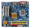
GA-8I945GZME-RH Motherboard Layout GA-8I945GZME-RH IT8718 KB_MS ATX_12V LGA775 CPU_FAN VGA COMA LPT ATX R_USB USB_LAN AUDIO SYS _FAN F_AUDIO HDA_SUR Marvell 8001 CODEC CD_IN COMB SPDIF_IO Intel 945GZ PCIE_16 DDRII1 DDRII2 IDE FDD PCI1 SATAII2 PCI2 ICH7 SATAII3 PCI3 BIOS - Gigabyte GA-8I945GZME-RH | Manual - Page 8
VGA PCI-ECLK (100MHz) LGA775 Processor Host Interface Intel 945GZ GMCH DDRII 533MHz DIMM Dual Channel Memory PCI Express x4 PCI Bus Marvell 8001 RJ45 Intel ICH7 CODEC BIOS 4 Serial ATA ATA33/66/100 IDE Channel IT8718 Floppy LPT Port COM Ports 3 PCI 8 USB Ports PS/2 KB/Mouse PCICLK (33MHz - Gigabyte GA-8I945GZME-RH | Manual - Page 9
instructions below: 1. Please turn off the computer and unplug its power cord. 2. When handling the motherboard, avoid touching any metal leads or connectors. 3. It is best to wear an electrostatic discharge (ESD) cuff when handling electronic components (CPU, RAM motherboard a problem related manual. - Gigabyte GA-8I945GZME-RH | Manual - Page 10
fan connector Š 1 front panel connector Š 1 front audio connector Š 1 CD In connector Š 1 COMB connector Š 1 power LED connector Š 2 USB 2.0/1.1 connectors for additional 4 USB 2.0/1.1 ports by cables Š 1 SPDIF In/Out connector Š 1 HDA_SUR connector GA-8I945GZME-RH Motherboard - 10 - - Gigabyte GA-8I945GZME-RH | Manual - Page 11
22.0cm (Note 1) For further CPU support information, please go to GIGABYTE's website. (Note 2) The GA-8I945GZME-RH supports up to PCI Express x4 mode. (please refer to the VGA cards support list on page 16) (Note 3) EasyTune functions may vary depending on different motherboards. - 11 - Hardware - Gigabyte GA-8I945GZME-RH | Manual - Page 12
specifications including the CPU, graphics card, memory, hard drive, CPU: An Intel® Pentium 4 Processor with HT Technology - Chipset: An Intel® Chipset that supports HT Technology - BIOS: A BIOS that supports the CPU during installation.) GA-8I945GZME-RH Motherboard - 12 - Fig. 4 Once the CPU is - Gigabyte GA-8I945GZME-RH | Manual - Page 13
sign on the male push pin doesn't face inwards before installation. (This instruction is only for Intel boxed fan) Fig. 3 Place the heatsink atop the CPU and make sure the push pins aim to the pin hole on the motherboard.Pressing down the push pins diagonally. Fig. 4 Please make sure the Male - Gigabyte GA-8I945GZME-RH | Manual - Page 14
fit in one direction. Insert the DIMM memory module vertically into the DIMM socket. Then push it down. Fig.2 Close the plastic clip at both edges of the DIMM sockets to lock the DIMM module. Reverse the installation steps when you wish to remove the DIMM module. GA-8I945GZME-RH Motherboard - 14 - - Gigabyte GA-8I945GZME-RH | Manual - Page 15
Memory Configuration The GA-8I945GZME-RH supports the Dual Channel Technology. After operating the Dual Channel Technology, the bandwidth of Memory Bus will double. Due to CPU BIOS utility of expansion card from BIOS. 8. Install related driver from the operating system. Installing a PCI Express - Gigabyte GA-8I945GZME-RH | Manual - Page 16
all supported under the Windows XP operating system. When using an add-on graphics card, please first delete the onboard graphics driver before installing the driver for the add-on graphics card.) Figure 1. PCI Express x16 Cards Graphics Chip Nvidia ATi Maker Gigabyte Gigabyte Gigabyte Gigabyte - Gigabyte GA-8I945GZME-RH | Manual - Page 17
sure your OS supports USB controller. If your OS does not support USB controller, please contact OS vendor for possible patch or driver upgrade. For more information please contact your OS or device(s) vendors. LAN Port The provided Internet connection is Gigabit Ethernet, providing data transfer - Gigabyte GA-8I945GZME-RH | Manual - Page 18
) CD_IN 3) CPU_FAN 12) SPDIF_IO 4) SYS_FAN 13) HDA_SUR 5) IDE 14) F_USB1 / F_USB2 6) FDD 15) COMB 7) SATAII0 / SATAII1 /S ATAII2 / SATAII3 16) C I 8) PWR_LED 17) CLR_CMOS 9) F_AUDIO 18) BAT GA-8I945GZME-RH Motherboard - 18 - - Gigabyte GA-8I945GZME-RH | Manual - Page 19
all components and devices are properly installed. Align the power connector with its proper location on the motherboard and connect tightly. The ATX_12V power connector mainly supplies power to the CPU. If the ATX_12V power connector is not connected, the system will not start. Caution! Please use - Gigabyte GA-8I945GZME-RH | Manual - Page 20
). Remember to connect the CPU/system fan cable to the CPU_FAN/SYS_FAN connector to prevent CPU damage or system hanging caused instructions located on the IDE device). Before attaching the IDE cable, please take note of the foolproof groove in the IDE connector. 40 39 GA-8I945GZME-RH Motherboard - Gigabyte GA-8I945GZME-RH | Manual - Page 21
the cable connects to the FDD drive. The types of FDD drives supported are: 360KB, 720KB, 1.2MB, 1.44MB and 2.88MB. Before provide up to 300MB/s transfer rate. Please refer to the BIOS setting for the SATA 3Gb/s and install the proper driver in order to work properly. 1 SATAII2 7 1 SATAII0 7 - Gigabyte GA-8I945GZME-RH | Manual - Page 22
Line Out (R) 6 NC 7 NC 8 No Pin 9 Line Out (L) 10 NC By default, the audio driver is configured to support HD Audio. To connect an AC97 front panel audio module to this connector, please refer to the instructions on Page 65 about the software settings. GA-8I945GZME-RH Motherboard - 22 - - Gigabyte GA-8I945GZME-RH | Manual - Page 23
PW+ PWSPEAK+ SPEAK- 2 20 1 19 HD+ HD- RESRES+ NC HD (IDE Hard Disk Active LED) SPEAK (Speaker Connector) RES (Reset Switch) PW (Power Switch) MSG (Message LED/Power/Sleep LED) NC Reset Switch IDE Hard Disk Active LED Pin 1: LED anode(+) Pin 2: LED cathode(-) Pin 1: Power Pin 2- Pin 3: NC Pin - Gigabyte GA-8I945GZME-RH | Manual - Page 24
GND 4 CD-R 12) SPDIF_IO (SPDIF In/Out) The SPDIF output is capable of providing digital audio to external speakers or compressed AC3 data to an external Dolby Digital Decoder. Use this feature only when 1 2 3 4 5 6 Definition Power No Pin SPDIF SPDIFI GND GND GA-8I945GZME-RH Motherboard - 24 - - Gigabyte GA-8I945GZME-RH | Manual - Page 25
11 GND 12 S_SURR_JD 13 S_SURR_LL 14 SURR_RR 14) F_USB1/F_USB2 (Front USB Connectors) Be careful with the polarity of the front USB connector. Check the pin assignment carefully while you connect the front USB cable, incorrect connection between the cable and connector will make the device - Gigabyte GA-8I945GZME-RH | Manual - Page 26
Intrusion, Case Open) This 2-pin connector allows your system to detect if the chassis cover is removed. You can check the "Case Opened" status in BIOS Setup. Pin No. Definition 1 1 Signal 2 GND GA-8I945GZME-RH Motherboard - 26 - - Gigabyte GA-8I945GZME-RH | Manual - Page 27
. Open: Normal Short: Clear CMOS 18) BATTERY Danger of explosion if battery is incorrectly replaced. Replace only with the same or equivalent type recommended by the manufacturer. Dispose of used batteries according to the manufacturer's instructions. If you want to erase CMOS... 1. Turn off the - Gigabyte GA-8I945GZME-RH | Manual - Page 28
English GA-8I945GZME-RH Motherboard - 28 - - Gigabyte GA-8I945GZME-RH | Manual - Page 29
BIOS, either GIGABYTE's Q-Flash or @BIOS utility can be used. Q-Flash allows the user to quickly and easily update or backup BIOS without entering the operating system. @BIOS is a Windows-based utility that does not require users to boot to DOS before upgrading BIOS but directly download and update - Gigabyte GA-8I945GZME-RH | Manual - Page 30
in the BIOS when somehow the system works not stable as usual. This action makes the system reset to the default for stability. The BIOS Setup menus described in this chapter are for reference only and may differ from the exact settings for your motherboard. GA-8I945GZME-RH Motherboard - 30 - Gigabyte GA-8I945GZME-RH | Manual - Page 31
, fan, speed. „ Frequency/Voltage Control This setup page is control CPU clock and frequency ratio. „ Load Fail-Safe Defaults Fail-Safe Defaults Save & Exit Setup Save CMOS value settings to CMOS and exit setup. „ Exit Without Saving Abandon all CMOS value changes and exit setup. - 31 - BIOS Setup - Gigabyte GA-8I945GZME-RH | Manual - Page 32
CMOS Features Wed, Apr 12 2006 14:31:24 Item Help Menu Level` ` IDE Channel 0 Master ` IDE Channel 0 Slave ` IDE Channel 2 Master ` IDE Channel 2 Slave ` IDE Channel 3 Master ` IDE Channel 3 Slave Drive A Floppy 3 Mode Support Halt On Base Memory Extended Memory GA-8I945GZME-RH Motherboard - 32 - - Gigabyte GA-8I945GZME-RH | Manual - Page 33
3 Mode Support (for Japan memory installed on the motherboard, or 640K for systems with 640K or more memory installed on the motherboard. Extended Memory The BIOS determines how much extended memory is present during the POST. This is the amount of memory located above 1 MB in the CPU's memory - Gigabyte GA-8I945GZME-RH | Manual - Page 34
be denied if the correct password is not entered at the prompt. (Default value) (Note) This item will show up when you install a processor which supports this function. GA-8I945GZME-RH Motherboard - 34 - - Gigabyte GA-8I945GZME-RH | Manual - Page 35
supported. Disabled (Default value) Disables CPU Hyper Threading. Limit CPUID Max. to 3 Enabled Limit CPUID Maximum value to 3 when use older OS like NT4. Disabled Disables CPUID Limit for windows XP. (Default value) No-Execute Memory which supports this function. - 35 - BIOS Setup - Gigabyte GA-8I945GZME-RH | Manual - Page 36
Set to USB Controller USB 2.0 Controller USB Keyboard Support USB Mouse Support Legacy USB storage detect Azalia Codec Onboard H/W LAN Onboard LAN Boot ROM /Slave. USB Controller Enabled Enable USB controller. (Default value) Disabled Disable USB controller. GA-8I945GZME-RH Motherboard - 36 - - Gigabyte GA-8I945GZME-RH | Manual - Page 37
USB mouse support. (Default value) Legacy USB storage detect Enabled Enable USB storage device boot. (Default value) Disabled Disable this function. Azalia Codec Auto Disabled Auto detect Azalia audio function. (Default value) Disable Azalia audio function. Onboard H/W LAN Auto BIOS will - Gigabyte GA-8I945GZME-RH | Manual - Page 38
Using Parallel port as ECP & EPP mode. ECP Mode Use DMA 3 Set ECP Mode Use DMA to 3. (Default value) 1 Set ECP Mode Use DMA to 1. GA-8I945GZME-RH Motherboard - 38 - - Gigabyte GA-8I945GZME-RH | Manual - Page 39
English 2-4 Power Management Setup CMOS Setup Utility-Copyright (C) Power On Suspend). (Default value) S3(STR) Set ACPI suspend type to S3/STR(Suspend To RAM). Soft-Off by PWR-BTTN Instant-Off Press power button then Power off instantly. (Default value) power on the system. - 39 - BIOS Setup - Gigabyte GA-8I945GZME-RH | Manual - Page 40
system, the system will be in "Off" state. (Default value) Full-On When AC-power back to the system, the system always in "On" state. Memory When AC-power back to the system, the system will return to the Last state before AC-power off. GA-8I945GZME-RH Motherboard - 40 - - Gigabyte GA-8I945GZME-RH | Manual - Page 41
English 2-5 PnP/PCI Configurations CMOS Setup Utility-Copyright (C) 1984-2006 Award Software PnP/PCI Configurations PCI 1 IRQ Assignment PCI 2 IRQ Assignment PCI 3 IRQ Assignment [Auto] PCI 2. Auto assign IRQ to PCI 3. (Default value) Set IRQ 3,4,5,7,9,10,11,12,14,15 to PCI 3. - 41 - BIOS Setup - Gigabyte GA-8I945GZME-RH | Manual - Page 42
at 70oC / 158oF. Monitor CPU temperature at 80oC / 176oF. Monitor CPU temperature at 90oC / 194oF. Disable this function. (Default value) CPU/System FAN Fail Warning Disabled Enabled Disable fan warning function. (Default value) Enable fan warning function. GA-8I945GZME-RH Motherboard - 42 - - Gigabyte GA-8I945GZME-RH | Manual - Page 43
cable. Note: In fact, the Voltage option can be used for CPU fans with 3-pin or 4-pin power cables. However, some 4-pin CPU fan power cables are not designed following Intel 4-Wire fans PWM control specifications. With such CPU fans, selecting PWM will not effectively reduce the fan speed. - 43 - Gigabyte GA-8I945GZME-RH | Manual - Page 44
Memory Frequency = Host clock X 2.66. Auto Set Memory frequency by DRAM SPD data. (Default value) Memory Frequency (Mhz) The values depend on "System Memory Multiplier" item. (Note) This item will show up when you install a processor which supports this function. GA-8I945GZME-RH Motherboard - Gigabyte GA-8I945GZME-RH | Manual - Page 45
of the system parameters that allow minimum system performance. 2-9 Load Optimized Defaults CMOS Setup Utility-Copyright (C) 1984-2006 Award Software ` Standard CMOS Features ` Advanced BIOS Features ` Integrated Peripherals ` Power Management Setup ` PnP/PCI Configurations ` PC Health Status - Gigabyte GA-8I945GZME-RH | Manual - Page 46
in Advance BIOS Features Menu, you will be prompted for the password every time the system is rebooted or any time you try to enter Setup Menu. If you select "Setup" at "Password Check" in Advance BIOS Features Menu, you will be prompted only when you try to enter Setup. GA-8I945GZME-RH Motherboard - Gigabyte GA-8I945GZME-RH | Manual - Page 47
Utility and save the user setup value to RTC CMOS. Type "N" will return to Setup Utility. 2-12 Exit Without Saving CMOS Setup Utility-Copyright (C) 1984-2006 Award Software ` Standard CMOS Features ` Advanced BIOS Features ` Integrated Peripherals ` Power Management Setup ` PnP/PCI Configurations - Gigabyte GA-8I945GZME-RH | Manual - Page 48
English GA-8I945GZME-RH Motherboard - 48 - - Gigabyte GA-8I945GZME-RH | Manual - Page 49
will continue to install other drivers. System will reboot automatically after install the drivers, afterward you can install others application. For USB2.0 driver support under Windows XP operating system, please use Windows Service Pack. After install Windows Service Pack, it will show a question - Gigabyte GA-8I945GZME-RH | Manual - Page 50
Applications This page displays all the tools that Gigabyte developed and some free software, you can choose anyone you want and press "install" to install them. 3-3 Driver CD Information This page lists the contents of software and drivers in this CD-title. GA-8I945GZME-RH Motherboard - 50 - - Gigabyte GA-8I945GZME-RH | Manual - Page 51
English 3-4 Hardware Information This page lists all device you have for this motherboard. 3-5 Contact Us Please see the last page for details. - 51 - Install Drivers - Gigabyte GA-8I945GZME-RH | Manual - Page 52
English GA-8I945GZME-RH Motherboard - 52 - - Gigabyte GA-8I945GZME-RH | Manual - Page 53
5 presents the most convenient Windows based system performance enhancement and manageability utility. Featuring several powerful yet easy to use tools such as 1) Overclocking for enhancing system performance, 2) C.I.A. and M.I.B. for special enhancement for CPU and Memory, 3) Smart-Fan control for - Gigabyte GA-8I945GZME-RH | Manual - Page 54
restoration of hard disk data. Supporting Microsoft operating systems including Windows XP/2000/NT/98/Me and . System requirements: 1. Intel x86 platforms 2. At least 64M bytes of system memory 3. VESA-supported VGA cards How to use drivers as well as software. GA-8I945GZME-RH Motherboard - 54 - - Gigabyte GA-8I945GZME-RH | Manual - Page 55
4GB is recom- mended but the actual space is dependent on the size of the data to be backed up) 4. Capable of backing up hard disks installed with Windows operating systems including DOS and Windows XP/2000/NT/9x/Me. 5. USB hard disks are currently not supported. 6. Does not support RAID - Gigabyte GA-8I945GZME-RH | Manual - Page 56
Primary Master : FUJITSU MPE3170AT ED-03-08 Primary Slave : None Secondary Master : CREATIVEDVD-RM DVD1242E BC101 Secondary Slave : None Press DEL to enter SETUP / Dual BIOS / Q-Flash / F9 For Xpress Recovery 08/07/2003-i875P-6A79BG03C-00 GA-8I945GZME-RH Motherboard - 56 - - Gigabyte GA-8I945GZME-RH | Manual - Page 57
Data to Backup Load Default Settings Save Settings to CMOS Q-Flash Utility Load Main BIOS from Floppy Load Backup BIOS from Floppy Save Main BIOS to Floppy Save Backup BIOS to Floppy Enter : Run :Move ESC:Reset F10:Power Off Dual BIOS utility bar Q-FlashTM utility title bar Action bar Task - Gigabyte GA-8I945GZME-RH | Manual - Page 58
Save Main BIOS to Floppy Save Backup BIOS to Floppy Enter : Run :Move ESC:Reset F10:Power Off Do not turn off power or reset your system at this stage!! After BIOS file is read, you'll see a confirmation dialog box asking you "Are you sure to update BIOS?" GA-8I945GZME-RH Motherboard - 58 - Gigabyte GA-8I945GZME-RH | Manual - Page 59
:Move ESC:Reset F10:Power Off After system reboots, you may find the BIOS version on your boot screen becomes the one you flashed. The BIOS file becomes Fab after updating. Award Modular BIOS v6.00PG, An Energy Star Ally Copyright (C) 1984-2003, Award Software, Inc. Intel i875P AGPset BIOS for - Gigabyte GA-8I945GZME-RH | Manual - Page 60
CMOS Press Y on your keyboard to save and exit. Part Two: Updating BIOS with Q-FlashTM Utility on Single-BIOS Motherboards. This part guides users of single-BIOS motherboards how to update BIOS using the Q-FlashTM utility. CMOS Time, Date, Hard Disk Type... GA-8I945GZME-RH Motherboard - 60 - - Gigabyte GA-8I945GZME-RH | Manual - Page 61
Enter : Run Keep DMI Data Enable Update BIOS from Floppy Save BIOS to Floppy :Move ESC:Reset F10:Power Off Action bar Task menu for download one BIOS file to the floppy disk so only one BIOS file, 8GE800.F4, is listed. Please confirm again you have the correct BIOS file for your motherboard - Gigabyte GA-8I945GZME-RH | Manual - Page 62
03/18/2003-I845GE-6A69YG01C-00 6. Press Del to enter BIOS menu after system reboots and "Load BIOS Fail-Safe Defaults". See how to Load BIOS Fail-Safe Defaults, please kindly refer to Step 6 to 7 in Part One. Congratulation!! You have updated BIOS successfully!! GA-8I945GZME-RH Motherboard - 62 - - Gigabyte GA-8I945GZME-RH | Manual - Page 63
click "Internet Update" icon b. Click "Update New BIOS" c. Please select "All Files" in dialog box while opening the old file. d. Please search for BIOS unzip file, downloading from internet or any other methods (such as: 8I945GZME-RH.F1). e. Complete update process following the instruction. - 63 - Gigabyte GA-8I945GZME-RH | Manual - Page 64
server, please go onto Gigabyte's web site for downloading and updating it according to method II. IV. Please note that any interruption during updating will cause system unbooted. V. Do not use @BIOS and C.O.M. (Corporate Online Management) at the same time. GA-8I945GZME-RH Motherboard - 64 - - Gigabyte GA-8I945GZME-RH | Manual - Page 65
English 4-1-4 2- / 4- / 6- / 8- Channel Audio Introduction This motherboard comes with three audio jacks. To set up multichannel surround sound, install an additional 5.1/7.1 surround cable (optional) and enable the feature through the audio driver. Installing the 5.1/7.1 Surround Cable (Optional) - Gigabyte GA-8I945GZME-RH | Manual - Page 66
. STEP 3: Connect a speaker or headphone to the rear Line Out jack, a small window will pop up and ask you what type of equipment is connected. Choose Headphone or Line Out depending on the device connected and click OK. The 2-channel audio setup is completed. GA-8I945GZME-RH Motherboard - 66 - - Gigabyte GA-8I945GZME-RH | Manual - Page 67
audio driver, you should find an Audio Manager icon in your system tray (you can also find the icon in Control Panel). Doubleclick the icon to open the Audio Control Panel. STEP 2: In the Audio Control Panel, click the Audio the audio jacks on the motherboard and the surround cable, a small window - Gigabyte GA-8I945GZME-RH | Manual - Page 68
6-channel speakers to the audio jacks on the motherboard and the surround cable, a small window will pop up and ask audio consists of Front Speaker Out (Line Out), Rear Speaker Out, and Center/Subwoofer Speaker Out) then click OK. The 6-channel audio setup is completed. GA-8I945GZME-RH Motherboard - Gigabyte GA-8I945GZME-RH | Manual - Page 69
audio driver, you should find an Audio Manager icon in your system tray (you can also find the icon in Control Panel). Doubleclick the icon to open the Audio Control Panel. STEP 2: In the Audio Control Panel, click the Audio the audio jacks on the motherboard and the surround cable, a small window - Gigabyte GA-8I945GZME-RH | Manual - Page 70
panel audio connector to support AC97 Audio mode, go to the Audio Control Panel and click the Audio I/O tab. In the ANALOG area, click the Tool icon and then select the Disable front panel jack detection check box. This action completes the AC'97 Audio configuration. GA-8I945GZME-RH Motherboard - Gigabyte GA-8I945GZME-RH | Manual - Page 71
English 4-2 Troubleshooting Below is a collection of general asked questions. To check general asked questions based on a specific motherboard model, please log on to http://www.gigabyte.com.tw Question 1: I cannot see some options that were included in previous BIOS after updating BIOS. Why? - Gigabyte GA-8I945GZME-RH | Manual - Page 72
English GA-8I945GZME-RH Motherboard - 72 - - Gigabyte GA-8I945GZME-RH | Manual - Page 73
- 73 - Appendix English - Gigabyte GA-8I945GZME-RH | Manual - Page 74
English GA-8I945GZME-RH Motherboard - 74 - - Gigabyte GA-8I945GZME-RH | Manual - Page 75
- 75 - Appendix English - Gigabyte GA-8I945GZME-RH | Manual - Page 76
English GA-8I945GZME-RH Motherboard - 76 - - Gigabyte GA-8I945GZME-RH | Manual - Page 77
- 77 - Appendix English - Gigabyte GA-8I945GZME-RH | Manual - Page 78
English GA-8I945GZME-RH Motherboard - 78 - - Gigabyte GA-8I945GZME-RH | Manual - Page 79
(Soporte de habla hispano) FAX: +1-626-854-9339 Correo: [email protected] Tech. Support: http://rma.gigabyte-usa.com Web address: http://www.gigabyte-latam.com y Japan NIPPON GIGA-BYTE CORPORATION WEB address : http://www.gigabyte.co.jp y Singapore GIGA-BYTE SINGAPORE PTE. LTD. WEB address - Gigabyte GA-8I945GZME-RH | Manual - Page 80
Ltd. in SERBIA & MONTENEGRO WEB address : http://www.gigabyte.co.yu y GIGABYTE Global Service System To submit a technical or non-technical (Sales/ Marketing) question, please link to : http://ggts.gigabyte.com.tw Then select your language to enter the system. GA-8I945GZME-RH Motherboard - 80 -
-
 1
1 -
 2
2 -
 3
3 -
 4
4 -
 5
5 -
 6
6 -
 7
7 -
8
-
9
-
10
-
11
-
12
-
13
-
14
-
15
-
16
-
17
-
18
-
19
-
20
-
21
-
22
-
23
-
24
-
25
-
26
-
27
-
28
-
29
-
30
-
31
-
32
-
33
-
34
-
35
-
36
-
37
-
38
-
39
-
40
-
41
-
42
-
43
-
44
-
45
-
46
-
47
-
48
-
49
-
50
-
51
-
52
-
53
-
54
-
55
-
56
-
57
-
58
-
59
-
60
-
61
-
62
-
63
-
64
-
65
-
66
-
67
-
68
-
69
-
70
-
71
-
72
-
73
-
74
-
75
-
76
-
77
-
78
-
79
-
80
 |
 |

GA-8I945GZME-RH
Intel
®
Pentium
®
4
LGA775 Processor Motherboard
User's Manual
Rev. 1003
12ME-945GZMER-1003R
*
The WEEE marking on the product indicates this product must not be disposed of with user's other household waste
and must be handed over to a designated collection point for the recycling of waste electrical and electronic equipment!!
*
The WEEE marking applies only in European Union's member states.