Gigabyte GA-8I945P-G Manual
Gigabyte GA-8I945P-G Manual
 |
View all Gigabyte GA-8I945P-G manuals
Add to My Manuals
Save this manual to your list of manuals |
Gigabyte GA-8I945P-G manual content summary:
- Gigabyte GA-8I945P-G | Manual - Page 1
GA-8I945P Pro/ GA-8I945P-G Intel® Pentium® D / Pentium® 4 LGA775 Processor Motherboard User's Manual Rev. 1005 12ME-8I945PP-1005 * The WEEE marking on the product indicates this product must not be disposed of with user's other household waste and - Gigabyte GA-8I945P-G | Manual - Page 2
Motherboard GA-8I945P Pro/GA-8I945P-G Apr. 18, 2005 Motherboard GA-8I945P Pro/GA-8I945P-G Apr. 18, 2005 - Gigabyte GA-8I945P-G | Manual - Page 3
product information and specifications, please carefully read the "Product User Manual". „ For detailed information related to Gigabyte's unique features, please go to "Technology Guide" section on Gigabyte's website to read or download the information you need. For more product details, please - Gigabyte GA-8I945P-G | Manual - Page 4
Table of Contents GA-8I945P Pro/GA-8I945P-G Motherboard Layout 6 Block Diagram ...7 Chapter 1 Hardware Installation 9 1-1 Considerations Prior to Installation 9 1-2 Feature Summary 10 1-3 Installation of the CPU and Heatsink 12 1-3-1 Installation of the CPU 12 1-3-2 Installation of the - Gigabyte GA-8I945P-G | Manual - Page 5
55 4-1-1 EasyTune 5 Introduction 56 4-1-2 Xpress Recovery2 Introduction 57 4-1-3 Flash BIOS Method Introduction 59 4-1-4 Serial ATA BIOS Setting Utility Introduction 70 4-1-5 2- / 4- / 6- / 8- Channel Audio Function Introduction 77 4-2 Troubleshooting 81 Only for GA-8I945P Pro. - 5 - - Gigabyte GA-8I945P-G | Manual - Page 6
x 2 & FDD Cable x 1 Serial ATAII Cable x 2 Serial ATA Power Cable x 2 2 Ports USB 2.0 + 2 Ports 1394 Cable x 1 I/O Shield * The items listed above are for reference only, and are subject to change without notice. Optional Accessories Š 8-Channel Audio Combo kit (Part Number: 12CR1-1SPAUD-21/R) - 6 - - Gigabyte GA-8I945P-G | Manual - Page 7
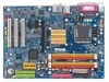
GA-8I945P Pro/GA-8I945P-G Motherboard Layout KB_MS ATX_12V CPU_FAN COAXIAL LGA775 ATX OPTICAL PWR_FAN LPT LAN COMA GA-8I945P (Pro)(-G) R_USB USB FDD AUDIO1 AUDIO2 F_AUDIO Intel 945P Broadcom 5789 CD_IN CODEC IT8712 NB_FAN PCIE_16 PCIE_1 PCIE_2 Main BIOS Back BIOS ICH7R / ICH7 - Gigabyte GA-8I945P-G | Manual - Page 8
RAID Host Interface Intel 945P Intel ICH7R / ICH7 DDRII 667(Note)/533/400MHz DIMM Dual Channel Memory MCHCLK (133/200/266MHz) 66MHz 33MHz 14.318MHz 48MHz Dual BIOS memory module on the motherboard, you must install an 800/1066MHz FSB processor . Only for GA-8I945P Pro. Only for GA-8I945P-G. - 8 - - Gigabyte GA-8I945P-G | Manual - Page 9
instructions below: 1. Please turn off the computer and unplug its power cord. 2. When handling the motherboard , avoid touching any metal leads or connectors. 3. It is best to wear an electrostatic discharge (ESD) cuff when handling electronic components (CPU, RAM motherboard problem manual - Gigabyte GA-8I945P-G | Manual - Page 10
/800/533MHz FSB L2 cache varies with CPU Northbridge: Intel® 945P Express Chipset Southbridge: Intel® ICH7R / ICH7 Supported on the Win 2000/XP operating systems 4 DDR II DIMM memory slots (supports up to 4GB memory) (Note 2) Supports 1.8V DDR II DIMM Supports dual channel DDR II 667(Note 3)/533/400 - Gigabyte GA-8I945P-G | Manual - Page 11
CPU / System / Power fan failure warning CPU smart fan control Use of licensed AWARD BIOS Supports Q-Flash/Multilanguage /Dual BIOS Supports @BIOS Supports EasyTune 5 Over Voltage via BIOS (CPU/DDR/PCIE/FSB) Over Clock via BIOS (CPU/DDR/PCIE) ATX form factor; 30.5cm x 22.0cm Only for GA-8I945P Pro - Gigabyte GA-8I945P-G | Manual - Page 12
- CPU: An Intel® Pentium 4 Processor with HT Technology - Chipset: An Intel® Chipset that supports HT Technology - BIOS: A BIOS that supports HT that might cause damage to the CPU during installation.) GA-8I945P (Pro)(-G) Motherboard - 12 - Fig. 4 Once the CPU is properly inserted, please replace - Gigabyte GA-8I945P-G | Manual - Page 13
the CPU and make sure the push pins aim to the pin hole on the motherboard.Pressing down the push pins diagonally. Fig. 4 Please make sure the Male and Female push pin are joined closely. (for detailed installation instructions, please refer to the heatsink installation section of the user manual - Gigabyte GA-8I945P-G | Manual - Page 14
. The motherboard supports DDR II memory modules, whereby BIOS will automatically detect memory capacity and specifications. Memory modules are designed so that they can be inserted only in one direction. The memory capacity used can differ with each slot. Only for GA-8I945P Pro. GA-8I945P (Pro - Gigabyte GA-8I945P-G | Manual - Page 15
steps when you wish to remove the DIMM module. Dual Channel Memory Configuration GA-8I945P (Pro)(-G) supports the Dual Channel Technology. After operating the Dual Channel Technology, the bandwidth of Memory Bus will add double. GA-8I945P (Pro)(-G) includes 4 DIMM sockets, and each Channel has two - Gigabyte GA-8I945P-G | Manual - Page 16
outlined below: 1. Read the related expansion card's instruction document before install the expansion card into the on the computer, if necessary, setup BIOS utility of expansion card from BIOS. 8. Install related driver from the operating system. Installing a GA-8I945P (Pro)(-G) Motherboard - 16 - - Gigabyte GA-8I945P-G | Manual - Page 17
output port is capable of providing digital audio to external speakers or com pressed AC3 supports USB controller. If your OS does not support USB controller, please contact OS vendor for possible patch or driver upgrade. For more information please contact your OS or device(s) vendors. LAN - Gigabyte GA-8I945P-G | Manual - Page 18
the default speakers settings, the ~ audio jacks can be reconfigured to perform different functions via the audio software. Only microphones still MUST be 9) SATAII0 / SATAII1 / SATAII2 / SATAII3 10) F_AUDIO Only for GA-8I945P Pro. GA-8I945P (Pro)(-G) Motherboard 11) 12) 13) 14) 15) 16) 17) 18) 19 - Gigabyte GA-8I945P-G | Manual - Page 19
proper location on the motherboard and connect tightly. The ATX_12V power connector mainly supplies power to the CPU. If the ATX_12V to start. If you use a 24-pin ATX power supply, please remove the small cover on the power connector on the motherboard before plugging in the power cord ; Otherwise, - Gigabyte GA-8I945P-G | Manual - Page 20
to prevent system overheating and failure. Caution! Please remember to connect the power to the CPU fan to prevent CPU overheating and failure. 1 CPU_FAN 1 SYS_FAN/ PWR_FAN Pin No. 1 2 3 4 ) Pin No. Definition 1 +12V 2 GND 1 Only for GA-8I945P Pro. GA-8I945P (Pro)(-G) Motherboard - 20 - - Gigabyte GA-8I945P-G | Manual - Page 21
cable while the other end of the cable connects to the FDD drive. The types of FDD drives supported are: 360KB, 720KB, 1.2MB, 1.44MB and 2.88MB. Please connect the red power connector wire to , please refer to the instructions located on the IDE device). 40 39 2 1 - 21 - Hardware Installation - Gigabyte GA-8I945P-G | Manual - Page 22
Out (R) 6 NC 7 NC 8 No Pin 9 Line Out (L) 10 NC By default, the audio driver is configured to support HD Audio. To connect an AC97 front panel audio module to this connector, please refer to the instructions on Page 78 about the software settings. GA-8I945P (Pro)(-G) Motherboard - 22 - - Gigabyte GA-8I945P-G | Manual - Page 23
English 11) PWR_LED (Optional) PWR_LED is connect with the system power indicator to indicate whether the system is on/off. It will blink when the system enters suspend mode. Pin No. Definition 1 1 MPD+ 2 MPD- 3 MPD- 12) F_PANEL (Front Panel Jumper) Please connect the power LED, PC speaker - Gigabyte GA-8I945P-G | Manual - Page 24
English 13) CD_IN (CD IN) Connect CD-ROM or DVD-ROM audio out to the connector. Pin No. Definition 1 CD-L 1 2 GND 3 GND 4 CD-R 14) SPDIF_I ( optional SPDIF cable, please contact your local dealer. Pin No. Definition 1 Power 1 2 SPDIFI 3 GND GA-8I945P (Pro)(-G) Motherboard - 24 - - Gigabyte GA-8I945P-G | Manual - Page 25
standby power when system is off and it does not support USB device to wake up from S3 mode. Users who wish to shut down the standby only when you use particular IEEE1394b cable. 2 F2_1394 16 Pin No. Definition 1 Power Only for GA-8I945P Pro. 1 F1_1394 2 1 Pin No. 1 2 3 4 5 6 7 8 9 10 15 - Gigabyte GA-8I945P-G | Manual - Page 26
you connect the external device cable. Please contact your nearest dealer for the optional GIGABYTE external device. Pin No. Definition 1 Power 1 2 RFID_RI- 3 RF_TXD 4 the "Case Opened" status in BIOS Setup. Pin No. Definition 1 1 Signal 2 GND GA-8I945P (Pro)(-G) Motherboard - 26 - - Gigabyte GA-8I945P-G | Manual - Page 27
is incorrectly replaced. Replace only with the same or equivalent type recommended by the manufacturer. Dispose of used batteries according to the manufacturer's instructions. If you want to erase CMOS... 1. Turn OFF the computer and unplug the power cord. 2. Take out the battery gently and put it - Gigabyte GA-8I945P-G | Manual - Page 28
English GA-8I945P (Pro)(-G) Motherboard - 28 - - Gigabyte GA-8I945P-G | Manual - Page 29
at the bottom of the screen. Status Page Setup Menu / Option Page Setup Menu Press F1 to pop up a small help window that describes the appropriate keys to use and the possible selections for the highlighted item. To exit the Help Window press . Only for GA-8I945P Pro. - 29 - BIOS Setup - Gigabyte GA-8I945P-G | Manual - Page 30
Dual BIOS when CPU clock and frequency ratio. „ Select Language This setup page is select multi language. „ Load Fail-Safe Defaults Fail-Safe Defaults indicates the value of the system parameters which the system would be in safe configuration. Only for GA-8I945P Pro. GA-8I945P (Pro)(-G) Motherboard - Gigabyte GA-8I945P-G | Manual - Page 31
system. „ Save & Exit Setup Save CMOS value settings to CMOS and exit setup. „ Exit Without Saving Abandon all CMOS value changes and exit setup. - 31 - BIOS Setup - Gigabyte GA-8I945P-G | Manual - Page 32
Drive B Floppy 3 Mode Suport Halt On Base Memory Extended Memory Total Memory [1.44M, 3.5"] [None] [Disabled] [All, from Sun to Sat, determined by the BIOS and is display only The month, Jan start up. Manual User can manually input the correct GA-8I945P Pro. GA-8I945P (Pro)(-G) Motherboard - 32 - - Gigabyte GA-8I945P-G | Manual - Page 33
. Floppy 3 Mode Support (for Japan Area) memory installed on the motherboard. Extended Memory The BIOS determines how much extended memory is present during the POST. This is the amount of memory located above 1 MB in the CPU's memory address map. Total Memory This item displays the memory - Gigabyte GA-8I945P-G | Manual - Page 34
you want to cancel the setting of password, please just press ENTER to make [SETUP] empty. (Note) This item will show up when you install a processor which supports this function. Only for GA-8I945P Pro. GA-8I945P (Pro)(-G) Motherboard - 34 - - Gigabyte GA-8I945P-G | Manual - Page 35
operating system with multi processors mode supported. (Default value) Disables CPU Hyper Threading. Limit CPUID Max. to 3 Enabled Disabled Limit CPUID Maximum value to 3 when use older OS like NT4. Disables CPUID Limit for windows XP. (Default value) No-Execute Memory Protect (Note) Enabled - Gigabyte GA-8I945P-G | Manual - Page 36
Support USB Mouse Support Azalia Codec Onboard H/W 1394 1 Onboard H/W GigaRAID GigaRAID Function Onboard H/W LAN Onboard LAN Boot ROM Onboard Serial Port 1 G-Keyless Port [Enabled] [Enabled] [RAID Disable onboard 2nd channel IDE port. Only for GA-8I945P Pro. GA-8I945P (Pro)(-G) Motherboard - 36 - - Gigabyte GA-8I945P-G | Manual - Page 37
Keyboard Support. (Default value) USB Mouse Support Enabled Enable USB Mouse Support. Disabled Disable USB Mouse Support. (Default value) Azalia Codec Auto Disabled Auto detect Azalia audio function. (Default value) Disable Azalia audio function. Only for GA-8I945P Pro. - 37 - BIOS Setup - Gigabyte GA-8I945P-G | Manual - Page 38
the boot ROM of the onboard LAN chip. Enabled Enable this function. Disabled Disable this function. (Default value) Onboard Serial Port 1 Auto BIOS will automatically setup the port (Default value) 1 Set ECP Mode Use DMA to 1. Only for GA-8I945P Pro. GA-8I945P (Pro)(-G) Motherboard - 38 - - Gigabyte GA-8I945P-G | Manual - Page 39
POS) Set ACPI suspend type to S1/POS(Power On Suspend). (Default value) S3(STR) Set ACPI suspend type to S3/STR(Suspend To RAM). Soft-off by PWR-BTTN Instant-off Press power button then Power off instantly /2 mouse left button to power on the system. Only for GA-8I945P Pro. - 39 - BIOS Setup - Gigabyte GA-8I945P-G | Manual - Page 40
system, the system will be in "Off" state. Full-On (Default value) When AC-power back to the system, the system always in "On" state. Memory When AC-power back to the system, the system will return to the Last state before AC-power off. GA-8I945P (Pro)(-G) Motherboard - 40 - - Gigabyte GA-8I945P-G | Manual - Page 41
3,4,5,7,9,10,11,12,14,15 to PCI 1. Auto assign IRQ to PCI 2. (Default value) Set IRQ 3,4,5,7,9,10,11,12,14,15 to PCI 2. Only for GA-8I945P Pro. - 41 - BIOS Setup - Gigabyte GA-8I945P-G | Manual - Page 42
CPU temperature at 80oC / 176oF. Monitor CPU temperature at 90oC / 194oF. Disable this function. (Default value) CPU/POWER /SYSTEM FAN Fail Warning Disabled Enabled Fan warning function disable. (Default value) Fan warning function enable. Only for GA-8I945P Pro. GA-8I945P (Pro)(-G) Motherboard - Gigabyte GA-8I945P-G | Manual - Page 43
with Easy Tune based on their requirements. (Default Value) CPU Smart FAN Mode This option is available only when CPU Smart FAN Control is enabled. Auto BIOS autodetects the type of CPU fan you installed and sets the optimal CPU Smart FAN control mode for it. (Default Value) Voltage Set - Gigabyte GA-8I945P-G | Manual - Page 44
increase CPU frequency(7%,9%) by CPU loading. Racing Set C.I.A.2 to Racing. (Automatically increase CPU frequency(9%,11%) by CPU loading. (Note) This item will show up when you install a processor which supports this function. Only for GA-8I945P Pro. GA-8I945P (Pro)(-G) Motherboard - 44 - Gigabyte GA-8I945P-G | Manual - Page 45
4 processor, please set "CPU Host Frequency" to 200MHz. Incorrect using it may cause your system broken. For power End-User use only! PCI Experss Frequency (Mhz) Auto 90~150 Set PCI Express frequency automatically. (Default value) Set PCI Express frequency from 90MHz to 150MHz. System Memory - Gigabyte GA-8I945P-G | Manual - Page 46
OverVoltage Control to +0.1V. Set FSB OverVoltage Control to +0.2V. Set FSB OverVoltage Control to +0.3V. CPU Voltage Control Supports adjustable CPU Vcore from 0.8375V to 1.6000V. (Default value: Normal) Normal CPU Vcore Display your CPU Vcore Voltage. GA-8I945P (Pro)(-G) Motherboard - 46 - - Gigabyte GA-8I945P-G | Manual - Page 47
(M.I.T.) Exit Without Saving ESC: Quit F8: Dual BIOS1/Q-Flash F3: Change Language 1 F10: Save & Exit Setup Load Fail-Safe Defaults Fail-Safe defaults contain the most appropriate values of the system parameters that allow minimum system performance. Only for GA-8I945P Pro. - 47 - BIOS Setup - Gigabyte GA-8I945P-G | Manual - Page 48
Dual BIOS1/Q-Flash F3: Change Language 1 F10: Save & Exit Setup Load Optimized Defaults Selecting this field loads the factory defaults for BIOS and Chipset BIOS Features Menu, you will be prompted only when you try to enter Setup. Only for GA-8I945P Pro. GA-8I945P (Pro)(-G) Motherboard - 48 - - Gigabyte GA-8I945P-G | Manual - Page 49
and EXIT S(Yav/Ne )&? YExit Setup ` MB Intelligent Tweaker(M.I.T.) Exit Without Saving ESC: Quit F8: Dual BIOS1/Q-Flash F3: Change Language 1 F10: Save & Exit Setup Save Data to CMOS Type "Y" will RTC CMOS. Type "N" will return to Setup Utility. Only for GA-8I945P Pro. - 49 - BIOS Setup - Gigabyte GA-8I945P-G | Manual - Page 50
English GA-8I945P (Pro)(-G) Motherboard - 50 - - Gigabyte GA-8I945P-G | Manual - Page 51
shown in Windows XP. Insert the driver CD-title that came with your motherboard into your CD-ROM drive, the driver CD-title will auto start and show the installation guide. If not, please double click the CD-ROM device icon in "My computer", and execute the Run.exe. 3-1 Install Chipset Drivers After - Gigabyte GA-8I945P-G | Manual - Page 52
Applications This page displays all the tools that Gigabyte developed and some free software, you can choose anyone you want and press "install" to install them. 3-3 Driver CD Information This page lists the contents of software and drivers in this CD-title. GA-8I945P (Pro)(-G) Motherboard - 52 - - Gigabyte GA-8I945P-G | Manual - Page 53
English 3-4 Hardware Information This page lists all device you have for this motherboard. 3-5 Contact Us Please see the last page for details. - 53 - Install Drivers - Gigabyte GA-8I945P-G | Manual - Page 54
English GA-8I945P (Pro)(-G) Motherboard - 54 - - Gigabyte GA-8I945P-G | Manual - Page 55
current system information as well as displaying a detailed list of all new drivers with the option for download. C.O.M. (Corporate Online Management) A web-based system management tool that allows system hardware information such as CPU, memory, graphics card, etc. to be monitored and controlled - Gigabyte GA-8I945P-G | Manual - Page 56
Easy and Advance Mode Display panel of CPU frequency Shows the current functions status Log on to GIGABYTE website Display EasyTuneTM 5 Help file Quit or Minimize EasyTuneTM 5 software (Note) EasyTune 5 functions may vary depending on different motherboards. GA-8I945P (Pro)(-G) Motherboard - 56 - - Gigabyte GA-8I945P-G | Manual - Page 57
hard disk data. Supporting Microsoft operating systems including Windows XP/2000/NT At least 64M bytes of system memory 3. VESA-supported VGA cards How to use the BIOS v6.00PG, An Energy Star Ally Copyright (C) 1984-2005, Award Software, Inc. Intel 945 BIOS for 8I945P Pro F9a . . . . :BIOS - Gigabyte GA-8I945P-G | Manual - Page 58
this is a BIOS-related issue, it can be solved by BIOS update) GA-K8U GA-K8NXP-9 GA-K8U-9 GA-K8N Ultra-9 GA-K8NXP-SLI GA-K8NF-9 (PCB Ver. 1.0) GA-K8N Ultra-SLI GA-K8NE (PCB Ver. 1.0) GA-K8N Pro-SLI GA-K8NMF-9 GA-8I945P (Pro)(-G) Motherboard - 58 - GA-8N-SLI Royal GA-8N-SLI Pro GA-8N-SLI - Gigabyte GA-8I945P-G | Manual - Page 59
to Backup Load Default Settings Save Settings to CMOS Q-Flash Utility Update Main BIOS from Floppy Update Backup BIOS from Floppy Save Main BIOS to Floppy Save Backup BIOS to Floppy PgDn/PgUp: Modify : Move ESC: Reset 512K 512K F10: Power Off Only for GA-8I945P Pro. - 59 - Appendix - Gigabyte GA-8I945P-G | Manual - Page 60
Backup BIOS works normally and could automatically recover the Main BIOS. (This auto recovery utility is set by system automatically and can't be changed by user.) Load Default Settings Load dual BIOS default value. Save Settings to CMOS Save revised setting. GA-8I945P (Pro)(-G) Motherboard - 60 - Gigabyte GA-8I945P-G | Manual - Page 61
refer to Part Two. Part One: Updating BIOS with Q-FlashTM Utility on Dual BIOS Motherboards. Some of Gigabyte motherboards are equipped with dual BIOS. In the BIOS menu of the motherboards supporting Q-Flash and Dual BIOS, the Q-Flash utility and Dual BIOS utility are combined in the same screen - Gigabyte GA-8I945P-G | Manual - Page 62
pressing Enter key on your keyboard to enable execution of the task. Action bar: Contains the names of four actions needed to operate the Q-Flash/Dual BIOS utility. Pressing the buttons mentioned on your keyboards to perform these actions. GA-8I945P (Pro)(-G) Motherboard - 62 - - Gigabyte GA-8I945P-G | Manual - Page 63
flash and press Enter. In this example, we only download one BIOS file to the floppy disk so only one BIOS file, 8KNXPU.Fba, is listed. Please confirm again you have the correct BIOS file for your motherboard. Dual BIOS Utility Boot From Main Bios Main ROM Type/Size SST 49LF004A Backup ROM Type - Gigabyte GA-8I945P-G | Manual - Page 64
Channel Primary Master : FUJITSU MPE3170AT ED-03-08 Primary Slave : None Secondary Master : CREATIVEDVD-RM DVD1242E BC101 Secondary Slave : None Press DEL to enter SETUP / Dual BIOS / Q-Flash / F9 For Xpress Recovery 09/23/2003-i875P-6A79BG03C-00 GA-8I945P (Pro)(-G) Motherboard - 64 - - Gigabyte GA-8I945P-G | Manual - Page 65
F8: Dual BIOS/Q-Flash F3: Change Language F10: Save & Exit Setup Time, Date, Hard Disk Type... Press Y on your keyboard to save and exit. Part Two: Updating BIOS with Q-FlashTM Utility on Single-BIOS Motherboards. This part guides users of single-BIOS motherboards how to update BIOS using the - Gigabyte GA-8I945P-G | Manual - Page 66
:tRemeset F10:Power Off Do not turn off power or reset your system at this stage!! After BIOS file is read, you'll see a confirmation dialog box asking you "Are you sure to update BIOS?" Please do not take out the floppy disk when it begins flashing BIOS. GA-8I945P (Pro)(-G) Motherboard - 66 - - Gigabyte GA-8I945P-G | Manual - Page 67
file becomes F4 after updating Award Modular BIOS v6.00PG, An Energy Star Ally Copyright (C) 1984-2003, Award Software, Inc. Intel 845GE AGPSet BIOS for 8GE800 F4 Check System Health OK Main Processor : Intel Pentium(R) 4 1.7GHz (100x17.0) Memory Testing : 122880K OK - Gigabyte GA-8I945P-G | Manual - Page 68
Click "Update New BIOS" c. Please select "All Files" in dialog box while opening the old file. d. Please search for BIOS unzip file, downloading from internet or any other methods (such as: 8I945P Pro.F2a). e. Complete update process following the instruction. GA-8I945P (Pro)(-G) Motherboard - 68 - Gigabyte GA-8I945P-G | Manual - Page 69
II, be sure that motherboard's model name in BIOS unzip file are the same as your motherboard's. Otherwise, your system won't boot. III. In method I, if the BIOS file you need cannot be found in @BIOSTM server, please go onto Gigabyte's web site for downloading and updating it according to method - Gigabyte GA-8I945P-G | Manual - Page 70
English 4-1-4 Serial ATA BIOS Setting Utility Introduction RAID Levels RAID (Redundant Array of . The RAID levels which the Intel® ICH7R chipset supports are RAID 0, RAID 1, RAID 0+1 and RAID 5. RAID 0 (Striping) RAID 0 reads loss. Only for GA-8I945P Pro. GA-8I945P (Pro)(-G) Motherboard - 70 - - Gigabyte GA-8I945P-G | Manual - Page 71
. 3) Enter the motherboard BIOS and locate RAID setup (Please refer to the section on Integrated Peripherals). 4) Enter RAID setup in the BIOS and select the RAID type (For instance, enter Ctrl + I to select Intel RAID; Ctrl + S to select Silicon Image). 5) Complete driver installation. 6) Complete - Gigabyte GA-8I945P-G | Manual - Page 72
performance and redundancy. [ ]-Change [TAB]-Next [ESC]-Previous Menu [ENTER]-Select There are four RAID levels: RAID0(Stripe), RAID1(Mirror), RAID 0+1 (Striping + Mirroring) and RAID5. After selecting the RAID level, press Enter to select Strip Size. GA-8I945P (Pro)(-G) Motherboard - 72 - - Gigabyte GA-8I945P-G | Manual - Page 73
Size : Capacity : RAID_Volume0 RAID0(Stripe) Select Disks 128KB 223.5 GB Create Volume [ HELP ] The following are typical values: RAID 0 - 128KB RAID 1 - 64KB RAID 5 - 64KB [ ]-Change [TAB]-Next [ESC]-Previous Menu [ENTER]-Select Intel(R) Matrix Storage Manager option ROM V5.0.0.1011 ICH7R - Gigabyte GA-8I945P-G | Manual - Page 74
data on selected disks will be lost. Please press Y to complete the set-up of RAID. Intel(R) Matrix Storage Manager option ROM V5.0.0.1011 ICH7R wRAID5 Copyright(C) 2003-04 Intel Corporation volume [ ]-Change [TAB]-Next [ESC]-Previous Menu [ENTER]-Select GA-8I945P (Pro)(-G) Motherboard - 74 - - Gigabyte GA-8I945P-G | Manual - Page 75
Disk(0) 111.7GB Member Disk(0) [ ]-Select [ESC]-Exit [ENTER]-Select Menu Delete RAID Volume If you want to delete a RAID volume, please select the Delete RAID Volume option. Press Enter key and follow the instructions on the screen. Intel(R) Matrix Storage Manager option ROM V5.0.0.1011 ICH7R - Gigabyte GA-8I945P-G | Manual - Page 76
the GIGABYTE motherboard drive CD-ROM. From the CDROM drive (example: D:\) double click the MENU.exe file in the BootDrv folder. A command prompt window will open similar to that in Fig. 2. Note: In the menu list, Intel Matrix Storage Manager is Intel ICH7R chipset. GA-8I945P (Pro)(-G) Motherboard - Gigabyte GA-8I945P-G | Manual - Page 77
Connection and Settings: We recommend that you use the speaker with amplifier to acquire the best sound effect if the stereo output is applied. STEP 1 : After installation of the audio driver, you should find an Audio Manager icon in your system tray (you can also find the icon in Control Panel - Gigabyte GA-8I945P-G | Manual - Page 78
window will pop up and ask you what type of equipment is connected. Choose a device depending on the type of speaker connected (4-channel audio consists of Front Speaker Out (Line Out) and Rear Speaker Out and then click OK. The 4-channel audio setup is completed. GA-8I945P (Pro)(-G) Motherboard - Gigabyte GA-8I945P-G | Manual - Page 79
Control Panel). Double-click the icon to open the Audio Control Panel. STEP 2: In the Audio Control Panel, click the Audio I/O tab. In the upper left list, click 6CH Speaker. STEP 3: After plugging in 6-channel speakers to the rear speaker jacks, a small window will pop up and ask you what type of - Gigabyte GA-8I945P-G | Manual - Page 80
panel audio connector to support AC97 Audio mode, go to the Audio Control Panel and click the Audio I/O tab. In the ANALOG area, click the Tool icon and then select the Disable front panel jack detection check box. This action completes the AC'97 Audio configuration. GA-8I945P (Pro)(-G) Motherboard - Gigabyte GA-8I945P-G | Manual - Page 81
of general asked questions. To check general asked questions based on a specific motherboard model, please log on to http://www.gigabyte.com.tw Question 1: I cannot see some options that were included in previous BIOS after updating BIOS. Why? Answer: Some advanced options are hidden in new - Gigabyte GA-8I945P-G | Manual - Page 82
English GA-8I945P (Pro)(-G) Motherboard - 82 - - Gigabyte GA-8I945P-G | Manual - Page 83
- 83 - Appendix English - Gigabyte GA-8I945P-G | Manual - Page 84
English GA-8I945P (Pro)(-G) Motherboard - 84 - - Gigabyte GA-8I945P-G | Manual - Page 85
- 85 - Appendix English - Gigabyte GA-8I945P-G | Manual - Page 86
English GA-8I945P (Pro)(-G) Motherboard - 86 - - Gigabyte GA-8I945P-G | Manual - Page 87
.giga-byte.com U.S.A. G.B.T. INC. TEL: +1-626-854-9338 FAX: +1-626-854-9339 Tech. Support : http://tw.giga-byte.com/TechSupport/ServiceCenter.htm Non-Tech. Support(Sales/Marketing) : http://ggts.gigabyte.com.tw/nontech.asp WEB address : http://www.giga-byte.com Germany G.B.T. TECHNOLOGY TRADING GMBH - Gigabyte GA-8I945P-G | Manual - Page 88
Representative Office Of GIGA-BYTE Technology Co., Ltd. in Romania Tech. Support : http://tw.giga-byte.com/TechSupport/ServiceCenter.htm Non-Tech. Support(Sales/Marketing) : http://ggts.gigabyte.com.tw/nontech.asp WEB address: http://www.gigabyte.com.ro GA-8I945P (Pro)(-G) Motherboard - 88 -
-
 1
1 -
 2
2 -
 3
3 -
 4
4 -
 5
5 -
 6
6 -
 7
7 -
8
-
9
-
10
-
11
-
12
-
13
-
14
-
15
-
16
-
17
-
18
-
19
-
20
-
21
-
22
-
23
-
24
-
25
-
26
-
27
-
28
-
29
-
30
-
31
-
32
-
33
-
34
-
35
-
36
-
37
-
38
-
39
-
40
-
41
-
42
-
43
-
44
-
45
-
46
-
47
-
48
-
49
-
50
-
51
-
52
-
53
-
54
-
55
-
56
-
57
-
58
-
59
-
60
-
61
-
62
-
63
-
64
-
65
-
66
-
67
-
68
-
69
-
70
-
71
-
72
-
73
-
74
-
75
-
76
-
77
-
78
-
79
-
80
-
81
-
82
-
83
-
84
-
85
-
86
-
87
-
88
 |
 |

GA-8I945P Pro/
GA-8I945P-G
Intel
®
Pentium
®
D / Pentium
®
4 LGA775 Processor Motherboard
User's Manual
Rev. 1005
12ME-8I945PP-1005
*
The WEEE marking on the product indicates this product must not be disposed of with user's other household waste
and must be handed over to a designated collection point for the recycling of waste electrical and electronic equipment!!
*
The WEEE marking applies only in European Union's member states.