Gigabyte GA-8I945PLGE-RH Manual
Gigabyte GA-8I945PLGE-RH Manual
 |
View all Gigabyte GA-8I945PLGE-RH manuals
Add to My Manuals
Save this manual to your list of manuals |
Gigabyte GA-8I945PLGE-RH manual content summary:
- Gigabyte GA-8I945PLGE-RH | Manual - Page 1
GA-8I945PLGE-RH Intel® Pentium® D / Pentium® 4 LGA775 Processor Motherboard User's Manual Rev. 1001 12ME-945PLGER-1001R * The WEEE marking on the product indicates this product must not be disposed of with user's other household waste and - Gigabyte GA-8I945PLGE-RH | Manual - Page 2
Motherboard GA-8I945PLGE-RH Jan. 11, 2006 Motherboard GA-8I945PLGE-RH Jan. 11, 2006 - Gigabyte GA-8I945PLGE-RH | Manual - Page 3
product information and specifications, please carefully read the "Product User Manual". „ For detailed information related to Gigabyte's unique features, please go to "Technology Guide" section on Gigabyte's website to read or download the information you need. For more product details, please - Gigabyte GA-8I945PLGE-RH | Manual - Page 4
Table of Contents GA-8I945PLGE-RH Motherboard Layout 6 Block Diagram ...7 Chapter 1 Hardware Installation 9 1-1 Considerations Prior to Installation 9 1-2 Feature Summary 10 1-3 Installation of the CPU and Heatsink 12 1-3-1 Installation of the CPU 12 1-3-2 Installation of the Heatsink 13 1-4 - Gigabyte GA-8I945PLGE-RH | Manual - Page 5
51 3-5 Contact Us ...51 Chapter 4 Appendix 53 4-1 Unique Software Utilities 53 4-1-1 EasyTune 5 Introduction 54 4-1-2 Xpress Recovery2 Introduction 55 4-1-3 Flash BIOS Method Introduction 57 4-1-4 2- / 4- / 6- / 8- Channel Audio Function Introduction 66 4-2 Troubleshooting 71 - 5 - - Gigabyte GA-8I945PLGE-RH | Manual - Page 6
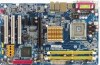
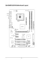
-8I945PLGE-RH Motherboard Layout KB_MS COAXIAL OPTICAL ATX_12V LGA775 CPU_FAN LPT GA-8I945PLGE-RH VGA_COM USB LAN USB AUDIO1 AUDIO2 F_AUDIO RTL 8111B SYS_FAN PCIE_16 Intel 945PL PCIE_1 CD_IN PCIE_2 CODEC PCI1 PCI2 IT8712 PCI3 CI FDD SPDIF_I RF_ID CLR_CMOS IDE1 BAT ICH7 BIOS - Gigabyte GA-8I945PLGE-RH | Manual - Page 7
100MHz) LGA775 Processor CPUCLK+/-(133/200MHz) PCI Express x16 2 PCI Express x1 RJ45 PCI-ECLK (100MHz) RTL 8111B x1 x1 x 1 PCI Express Bus PCI Bus Host Interface Intel 945PL Intel ICH7 DDRII 533/400MHz DIMM Dual Channel Memory MCHCLK (133/200MHz) 66MHz 33MHz 14.318MHz 48MHz BIOS 4 SATA - Gigabyte GA-8I945PLGE-RH | Manual - Page 8
- 8 - - Gigabyte GA-8I945PLGE-RH | Manual - Page 9
, please follow the instructions below: 1. Please turn handling electronic components (CPU, RAM). 4. Prior to information in the provided manual. 3. Before using the any installation steps or have a problem related to the use of the conditions recommended in the user manual. 3. Damage due to improper - Gigabyte GA-8I945PLGE-RH | Manual - Page 10
Feature Summary CPU Š Supports LGA775 Intel® Pentium® Processor Pentium® D / Pentium® 4 (Note 1) Š L2 cache varies with CPU Front Side Bus Š Supports 800/533MHz FSB Chipset Š Northbridge: Intel® 945PL Chipset Š Southbridge: Intel® ICH7 LAN Š Onboard RTL8111B chip (10/100/1000 Mbit) Audio - Gigabyte GA-8I945PLGE-RH | Manual - Page 11
Š CPU smart fan control BIOS Š 1 4Mbit flash ROM Š Use of licensed AWARD BIOS Additional Features Š Supports @BIOS Š Supports Download Center Š Supports Q-Flash Š Supports EasyTune (Note 2) Š Supports Xpress Install Š Supports Xpress Recovery2 Š Supports Xpress Rescue Bundle Software - Gigabyte GA-8I945PLGE-RH | Manual - Page 12
- CPU: An Intel® Pentium 4 Processor with HT Technology - Chipset: An Intel® Chipset that supports HT Technology - BIOS: A BIOS that supports HT that might cause damage to the CPU during installation.) GA-8I945PLGE-RH Motherboard - 12 - Fig. 4 Once the CPU is properly inserted, please replace - Gigabyte GA-8I945PLGE-RH | Manual - Page 13
to install.) Please note the direction of arrow sign on the male push pin doesn't face inwards before installation. (This instruction is only for Intel boxed fan) Fig. 3 Place the heatsink atop the CPU and make sure the push pins aim to the pin hole on the motherboard.Pressing down the push pins - Gigabyte GA-8I945PLGE-RH | Manual - Page 14
fit in one direction. Insert the DIMM memory module vertically into the DIMM socket. Then push it down. Fig.2 Close the plastic clip at both edges of the DIMM sockets to lock the DIMM module. Reverse the installation steps when you wish to remove the DIMM module. GA-8I945PLGE-RH Motherboard - 14 - - Gigabyte GA-8I945PLGE-RH | Manual - Page 15
the Dual Channel Technology, the bandwidth of Memory Bus will add double. The GA-8I945PLGE-RH includes 2 DIMM sockets. If you want to operate the Dual Channel Technology, please note the following explanations due to the limitation of Intel chipset specifications. 1. Dual Channel mode will not be - Gigabyte GA-8I945PLGE-RH | Manual - Page 16
outlined below: 1. Read the related expansion card's instruction document before install the expansion card into the on the computer, if necessary, setup BIOS utility of expansion card from BIOS. 8. Install related driver from the operating system. Installing a GA-8I945PLGE-RH Motherboard - 16 - - Gigabyte GA-8I945PLGE-RH | Manual - Page 17
port is capable of providing digital audio to external speakers or compressed AC3 support USB controller, please contact OS vendor for possible patch or driver upgrade. For more information please contact your OS or device(s) vendors. LAN Port The provided Internet connection is Gigabit Ethernet - Gigabyte GA-8I945PLGE-RH | Manual - Page 18
addition to the default speakers settings, the ~ audio jacks can be reconfigured to perform different functions via the audio software. Only microphones still MUST be connected to the / SATAII1 / SATAII2 / SATAII3 16) CLR_CMOS 8) F_AUDIO 17) BAT 9) PWR_LED GA-8I945PLGE-RH Motherboard - 18 - - Gigabyte GA-8I945PLGE-RH | Manual - Page 19
installed. Align the power connector with its proper location on the motherboard and connect tightly. The ATX_12V power connector mainly supplies power to the CPU. If the ATX_12V power connector is not connected, the system will not start. Caution! Please use a power supply that is able to handle - Gigabyte GA-8I945PLGE-RH | Manual - Page 20
failure. Caution! Please remember to connect the power to the CPU fan to prevent CPU overheating and failure. 1 CPU_FAN 1 SYS_FAN Pin No. 1 supported are: 360KB, 720KB, 1.2MB, 1.44MB and 2.88MB. Please connect the red power connector wire to the pin1 position. 2 34 1 33 GA-8I945PLGE-RH - Gigabyte GA-8I945PLGE-RH | Manual - Page 21
other as Slave (for information on settings, please refer to the instructions located on the IDE device). 40 39 2 1 7) SATAII0/SATAII1 up to 300MB/s transfer rate. Please refer to the BIOS setting for the Serial ATA and install the proper driver in order to work properly. Pin No. Definition 1 - Gigabyte GA-8I945PLGE-RH | Manual - Page 22
to the instructions on Page 70 about the software settings. 9) PWR_LED PWR_LED is connected with the system power indicator to indicate whether the system is on/off. It will blink when the system enters suspend mode. Pin No. Definition 1 MPD+ 2 MPD- 1 3 MPD- GA-8I945PLGE-RH Motherboard - Gigabyte GA-8I945PLGE-RH | Manual - Page 23
English 10) F_PANEL (Front Panel Jumper) Please connect the power LED, PC speaker, reset switch and power switch etc of your chassis front panel to the F_PANEL connector according to the pin assignment below. Reset Switch IDE Hard Disk Active LED Speaker Connector Power Switch 20 19 SPEAK- - Gigabyte GA-8I945PLGE-RH | Manual - Page 24
English 11) CD_IN (CD IN) Connect CD-ROM or DVD-ROM audio out to the connector. Pin No. Definition 1 CD-L 1 2 GND 3 GND 4 CD-R 12) SPDIF_I ( optional SPDIF cable, please contact your local dealer. Pin No. Definition 1 Power 1 2 SPDIFI 3 GND GA-8I945PLGE-RH Motherboard - 24 - - Gigabyte GA-8I945PLGE-RH | Manual - Page 25
devices to use extra function. Check the pin assignments before you connect the external device cable. Please contact your nearest dealer for the optional GIGABYTE external device. Pin No. Definition 1 Power 1 2 RFID_RI- 3 RF_TXD 4 RF_RXD 5 NC 6 GND - 25 - Hardware Installation - Gigabyte GA-8I945PLGE-RH | Manual - Page 26
your system to detect if the chassis cover is removed. You can check the "Case Opened" status in BIOS Setup. Pin No. Definition 1 1 Signal 2 GND 16) CLR_CMOS (Clear CMOS) You may clear the from improper use this jumper. 1 Open: Normal 1 Short: Clear CMOS GA-8I945PLGE-RH Motherboard - 26 - - Gigabyte GA-8I945PLGE-RH | Manual - Page 27
is incorrectly replaced. Replace only with the same or equivalent type recommended by the manufacturer. Dispose of used batteries according to the manufacturer's instructions. If you want to erase CMOS... 1. Turn OFF the computer and unplug the power cord. 2. Take out the battery gently and put it - Gigabyte GA-8I945PLGE-RH | Manual - Page 28
English GA-8I945PLGE-RH Motherboard - 28 - - Gigabyte GA-8I945PLGE-RH | Manual - Page 29
BIOS, either Gigabyte's Q-Flash or @BIOS utility can be used. Q-Flash allows the user to quickly and easily update or backup BIOS without entering the operating system. @BIOS is a Windows-based utility that does not require users to boot to DOS before upgrading BIOS but directly download and update - Gigabyte GA-8I945PLGE-RH | Manual - Page 30
Modular BIOS v6.00PG, An Energy Star Ally Copyright (C) 1984-2004, Award Software, Inc. Intel I945 BIOS for 8I945PLGE-RH E6 . . . . :BIOS Setup USB-CDROM USB-HDD LAN KL:Move Enter :Accept ESC:Exit The Main Menu (For example: BIOS Ver. : F1a) Once you enter Award BIOS CMOS Setup Utility, the - Gigabyte GA-8I945PLGE-RH | Manual - Page 31
setup page includes all the items in standard compatible BIOS. „ Advanced BIOS Features This setup page includes all the items of voltage, fan, speed. „ MB Intelligent Tweaker(M.I.T.) This setup page is control CPU clock and frequency ratio. „ Load Fail-Safe Defaults Fail-Safe Defaults indicates - Gigabyte GA-8I945PLGE-RH | Manual - Page 32
Copyright (C) 1984-2005 Award Software Standard CMOS Features Fri, Mar B Floppy 3 Mode Support Halt On Base Memory Extended Memory Total Memory [None] [None] Sun to Sat, determined by the BIOS and is display only The month, up. Manual User can manually input GA-8I945PLGE-RH Motherboard - 32 - - Gigabyte GA-8I945PLGE-RH | Manual - Page 33
. Floppy 3 Mode Support (for Japan Area) memory installed on the motherboard. Extended Memory The BIOS determines how much extended memory is present during the POST. This is the amount of memory located above 1 MB in the CPU's memory address map. Total Memory This item displays the memory - Gigabyte GA-8I945PLGE-RH | Manual - Page 34
to cancel the setting of password, please just press ENTER to make [SETUP] empty. (Note) This item will show up when you install a processor which supports this function. GA-8I945PLGE-RH Motherboard - 34 - - Gigabyte GA-8I945PLGE-RH | Manual - Page 35
Disabled Disable CPUID Limit for windows XP. (Default value) No-Execute Memory Protect (Note) Enabled Disabled Enable No-Execute Memory Protect function. (Default value) Disable No-Execute Memory Protect function. CPU Enhanced Halt (C1E) (Note) Enabled Enable CPU Enhanced Halt (C1E) function - Gigabyte GA-8I945PLGE-RH | Manual - Page 36
SATA Mode" and "PATA IDE Set to". If PATA IDE were set to Ch. 0 Master/Slave,this function will auto set to Ch. 1 Master/Slave. GA-8I945PLGE-RH Motherboard - 36 - - Gigabyte GA-8I945PLGE-RH | Manual - Page 37
this function. Azalia Codec Auto Auto detect Azalia audio function. (Default value) Disabled Disable Azalia audio function. Onboard H/W LAN Enabled Disabled Enable Onboard H/W LAN function. (Default value) Disable this function. OnBoard LAN Boot ROM This function decide whether to invoke - Gigabyte GA-8I945PLGE-RH | Manual - Page 38
Power Management Setup CMOS Setup Utility-Copyright (C) 1984-2005 Award Software Power Management Setup ACPI Suspend Type Soft-Off by PWR-BTTN PME S3(STR) Set ACPI suspend type to S3/STR(Suspend To RAM). Soft-Off by PWR-BTTN Instant-Off Delay 4 Sec. Press GA-8I945PLGE-RH Motherboard - 38 - - Gigabyte GA-8I945PLGE-RH | Manual - Page 39
On password. AC BACK Function Soft-Off When AC-power back to the system, the system will be in "Off" state. (Default value) Full-On Memory When AC-power back to the system, the system always in "On" state. When AC-power back to the system, the system will return to - Gigabyte GA-8I945PLGE-RH | Manual - Page 40
English 2-5 PnP/PCI Configurations CMOS Setup Utility-Copyright (C) 1984-2005 Award Software PnP/PCI Configurations PCI 1 IRQ Assignment PCI 2 IRQ Assignment PCI 3 IRQ Assignment [Auto] [Auto to PCI 3. (Default value) Set IRQ 3,4,5,7,9,10,11,12,14,15 to PCI 3. GA-8I945PLGE-RH Motherboard - 40 - - Gigabyte GA-8I945PLGE-RH | Manual - Page 41
(C) 1984-2005 Award Software PC Health Status Reset Case Open Status Case Opened Vcore DDR18V +3.3V +12V Current CPU Temperature Current CPU FAN Speed Current SYSTEM FAN Speed CPU Warning Temperature CPU FAN Fail Warning SYSTEM FAN Fail Warning CPU Smart FAN Control CPU Smart FAN Mode [Disabled - Gigabyte GA-8I945PLGE-RH | Manual - Page 42
option can be used for CPU fans with 3-pin or 4-pin power cables. However, some 4-pin CPU fan power cables are not designed following Intel 4-Wire fans PWM control specifications. With such CPU fans, selecting PWM will not effectively reduce the fan speed. GA-8I945PLGE-RH Motherboard - 42 - - Gigabyte GA-8I945PLGE-RH | Manual - Page 43
Utility-Copyright (C) 1984-2005 Award Software MB Intelligent Tweaker(M.I.T.) CPU Clock Ratio (Note) C.A.M (Note) Robust Graphics Booster C.I.A. 2 CPU Host Clock Control x CPU Host Frequency (Mhz) x PCI Experss Frequency (Mhz) System Memory Multiplier Memory Frequency (Mhz) DIMM OverVoltage Control - Gigabyte GA-8I945PLGE-RH | Manual - Page 44
Memory Frequency = Host clock X 2.66. 3.00 Memory Frequency = Host clock X 3.00. 4.00 Memory Frequency = Host clock X 4.00. Auto Set Memory frequency by DRAM SPD data. (Default value) Memory Frequency (Mhz) The values depend on CPU power End-User use only! GA-8I945PLGE-RH Motherboard - 44 - - Gigabyte GA-8I945PLGE-RH | Manual - Page 45
+0.2V Set FSB OverVoltage Control to +0.1V. Set FSB OverVoltage Control to +0.2V. +0.3V Set FSB OverVoltage Control to +0.3V. CPU Voltage Control Supports adjustable CPU Vcore from 0.8375V to 1.6000V. (Default value: Normal) Normal CPU Vcore Display your CPU Vcore Voltage. - 45 - BIOS Setup - Gigabyte GA-8I945PLGE-RH | Manual - Page 46
(C) 1984-2005 Award Software ` Standard CMOS Features Load Fail-Safe Defaults ` Advanced BIOS Features Load Optimized Defaults Defaults Selecting this field loads the factory defaults for BIOS and Chipset Features which the system automatically detects. GA-8I945PLGE-RH Motherboard - 46 - - Gigabyte GA-8I945PLGE-RH | Manual - Page 47
English 2-10 Set Supervisor/User Password CMOS Setup Utility-Copyright (C) 1984-2005 Award Software ` Standard CMOS Features ` Advanced BIOS Features ` Integrated Peripherals ` Power Management Setup ` PnP/PCI ConfigurationEsnter Password: ` PC Health Status ` MB Intelligent Tweaker(M.I.T.) Load - Gigabyte GA-8I945PLGE-RH | Manual - Page 48
12 Exit Without Saving CMOS Setup Utility-Copyright (C) 1984-2005 Award Software ` Standard CMOS Features ` Advanced BIOS Features ` Integrated Peripherals ` Power Management Setup ` PnP/PCI without saving to RTC CMOS. Type "N" will return to Setup Utility. GA-8I945PLGE-RH Motherboard - 48 - - Gigabyte GA-8I945PLGE-RH | Manual - Page 49
shown in Windows XP. Insert the driver CD-title that came with your motherboard into your CD-ROM drive, the driver CD-title will auto start and show the installation guide. If not, please double click the CD-ROM device icon in "My computer", and execute the Run.exe. 3-1 Install Chipset Drivers After - Gigabyte GA-8I945PLGE-RH | Manual - Page 50
3-2 Software Applications This page displays all the tools that Gigabyte developed and some free software, you can choose anyone you want and press "install" to install them. 3-3 Driver CD Information This page lists the contents of software and drivers in this CD-title. GA-8I945PLGE-RH Motherboard - Gigabyte GA-8I945PLGE-RH | Manual - Page 51
English 3-4 Hardware Information This page lists all device you have for this motherboard. 3-5 Contact Us Please see the last page for details. - 51 - Install Drivers - Gigabyte GA-8I945PLGE-RH | Manual - Page 52
English GA-8I945PLGE-RH Motherboard - 52 - - Gigabyte GA-8I945PLGE-RH | Manual - Page 53
different modes within BIOS setup in order to change system settings such as the CPU system bus, memory timings or to enabled Gigabyte's unique C.I.A. Download Center Download Center allows users to quickly download and update their BIOS as well as the latest drivers for their system. Download - Gigabyte GA-8I945PLGE-RH | Manual - Page 54
Easy and Advance Mode Display panel of CPU frequency Shows the current functions status Log on to GIGABYTE website Display EasyTuneTM 5 Help file Quit or Minimize EasyTuneTM 5 software (Note) EasyTune 5 functions may vary depending on different motherboards. GA-8I945PLGE-RH Motherboard - 54 - - Gigabyte GA-8I945PLGE-RH | Manual - Page 55
disk data. Supporting Microsoft operating systems including Windows XP/2000/NT/98 1. Intel x86 platforms 2. At least 64M bytes of system memory 3. VESA-supported VGA cards BIOS v6.00PG, An Energy Star Ally Copyright (C) 1984-2004, Award Software, Inc. Intel 945 BIOS for 8I945GME E7 . . . . :BIOS - Gigabyte GA-8I945PLGE-RH | Manual - Page 56
(As this is a BIOS-related issue, it can be solved by BIOS update) GA-K8U GA-K8NXP-9 GA-K8U-9 GA-K8N Ultra-9 GA-K8NXP-SLI GA-K8NF-9 (PCB Ver. 1.0) GA-K8N Ultra-SLI GA-K8NE (PCB Ver. 1.0) GA-K8N Pro-SLI GA-K8NMF-9 GA-8I945PLGE-RH Motherboard - 56 - GA-8N-SLI Royal GA-8N-SLI Pro GA-8N-SLI - Gigabyte GA-8I945PLGE-RH | Manual - Page 57
, we take GA-8KNXP Ultra as the example to guide you how to flash BIOS from an older version to the latest version. For example, from Fa3 to Fba. The BIOS file is Fa3 before updating Award Modular BIOS v6.00PG, An Energy Star Ally Copyright (C) 1984-2003, Award Software, Inc. Intel i875P AGPset - Gigabyte GA-8I945PLGE-RH | Manual - Page 58
screen to enter BIOS menu. CMOS Setup Utility-Copyright (C) 1984-2004 Award Software Standard CMOS Features Advanced BIOS Features Integrated Peripherals the Q-Flash/Dual BIOS utility. Pressing the buttons mentioned on your keyboards to perform these actions. GA-8I945PLGE-RH Motherboard - 58 - - Gigabyte GA-8I945PLGE-RH | Manual - Page 59
flash and press Enter. In this example, we only download one BIOS file to the floppy disk so only one BIOS file, 8KNXPU.Fba, is listed. Please confirm again you have the correct BIOS file for your motherboard. Dual BIOS Utility Boot From Main Bios Main ROM Type/Size SST 49LF004A Backup ROM Type - Gigabyte GA-8I945PLGE-RH | Manual - Page 60
Memory Frequency 266 MHz in Single Channel Primary Master : FUJITSU MPE3170AT ED-03-08 Primary Slave : None Secondary Master : CREATIVEDVD-RM DVD1242E BC101 Secondary Slave : None Press DEL to enter SETUP / Dual BIOS / Q-Flash / F9 For Xpress Recovery 09/23/2003-i875P-6A79BG03C-00 GA-8I945PLGE-RH - Gigabyte GA-8I945PLGE-RH | Manual - Page 61
exit. Part Two: Updating BIOS with Q-FlashTM Utility on Single-BIOS Motherboards. This part guides users of single-BIOS motherboards how to update BIOS using the Q-FlashTM utility. CMOS Setup Utility-Copyright (C) 1984-2004 Award Software Standard CMOS Features Advanced BIOS Features Integrated - Gigabyte GA-8I945PLGE-RH | Manual - Page 62
SyCs:tRemeset F10:Power Off Do not trun off power or reset your system at this stage!! After BIOS file is read, you'll see a confirmation dialog box asking you "Are you sure to update BIOS?" Please do not take out the floppy disk when it begins flashing BIOS. GA-8I945PLGE-RH Motherboard - 62 - - Gigabyte GA-8I945PLGE-RH | Manual - Page 63
. The BIOS file becomes F4 after updating Award Modular BIOS v6.00PG, An Energy Star Ally Copyright (C) 1984-2003, Award Software, Inc. Intel 845GE AGPSet BIOS for 8GE800 F4 Check System Health OK Main Processor : Intel Pentium(R) 4 1.7GHz (100x17.0) Memory Testing - Gigabyte GA-8I945PLGE-RH | Manual - Page 64
Update" icon b. Click "Update New BIOS" c. Please select "All Files" in dialog box while opening the old file. d. Please search for BIOS unzip file, downloading from internet or any other methods (such as: 8I945PLGERH.F1). e. Complete update process following the instruction. GA-8I945PLGE-RH - Gigabyte GA-8I945PLGE-RH | Manual - Page 65
there is "Save Current BIOS" icon shown in dialog box. It means to save the current BIOS version. IV. Check out supported motherboard and Flash ROM: I, if the BIOS file you need cannot be found in @BIOSTM server, please go onto Gigabyte's web site for downloading and updating it according to method - Gigabyte GA-8I945PLGE-RH | Manual - Page 66
the best sound effect if the stereo output is applied. STEP 1 : After installation of the audio driver, you should find an Audio Manager icon in your system tray (you can also find the icon in Control Panel). Doubleclick the icon to open the Audio Control Panel. GA-8I945PLGE-RH Motherboard - 66 - Gigabyte GA-8I945PLGE-RH | Manual - Page 67
Line Out jack, a small window will pop up and ask you what type of equipment is connected. Choose Headphone or Line Out depending on the device connected and click OK. The 2-channel audio setup is completed. 4 Channel Audio Setup STEP 1 : After installation of the audio driver, you should find an - Gigabyte GA-8I945PLGE-RH | Manual - Page 68
audio setup is completed. 6 Channel Audio Setup STEP 1 : After installation of the audio driver, you should find an Audio audio consists of Front Speaker Out (Line Out), Rear Speaker Out, and Center/Subwoofer Speaker Out) then click OK. The 6-channel audio setup is completed. GA-8I945PLGE-RH - Gigabyte GA-8I945PLGE-RH | Manual - Page 69
Setup STEP 1 : After installation of the audio driver, you should find an Audio Manager icon in your system tray (you can also find the icon in Control Panel). Doubleclick the icon to open the Audio Control Panel. STEP 2: In the Audio Control Panel, click the Audio I/O tab. In the upper left list - Gigabyte GA-8I945PLGE-RH | Manual - Page 70
panel audio connector to support AC97 Audio mode, go to the Audio Control Panel and click the Audio I/O tab. In the ANALOG area, click the Tool icon and then select the Disable front panel jack detection check box. This action completes the AC'97 Audio configuration. GA-8I945PLGE-RH Motherboard - Gigabyte GA-8I945PLGE-RH | Manual - Page 71
Troubleshooting Below is a collection of general asked questions. To check general asked questions based on a specific motherboard model, please log on to www.gigabyte.com.tw Question 1: I cannot see some options that were included in previous BIOS after updating BIOS memory bad - 71 - AWARD BIOS - Gigabyte GA-8I945PLGE-RH | Manual - Page 72
English GA-8I945PLGE-RH Motherboard - 72 - - Gigabyte GA-8I945PLGE-RH | Manual - Page 73
- 73 - Appendix English - Gigabyte GA-8I945PLGE-RH | Manual - Page 74
English GA-8I945PLGE-RH Motherboard - 74 - - Gigabyte GA-8I945PLGE-RH | Manual - Page 75
- 75 - Appendix English - Gigabyte GA-8I945PLGE-RH | Manual - Page 76
English GA-8I945PLGE-RH Motherboard - 76 - - Gigabyte GA-8I945PLGE-RH | Manual - Page 77
- 77 - Appendix English - Gigabyte GA-8I945PLGE-RH | Manual - Page 78
English GA-8I945PLGE-RH Motherboard - 78 - - Gigabyte GA-8I945PLGE-RH | Manual - Page 79
.giga-byte.com U.S.A. G.B.T. INC. TEL: +1-626-854-9338 FAX: +1-626-854-9339 Tech. Support : http://tw.giga-byte.com/TechSupport/ServiceCenter.htm Non-Tech. Support(Sales/Marketing) : http://ggts.gigabyte.com.tw/nontech.asp WEB address : http://www.giga-byte.com Germany G.B.T. TECHNOLOGY TRADING GMBH - Gigabyte GA-8I945PLGE-RH | Manual - Page 80
://www.gigabyte.cz Romania Representative Office Of GIGA-BYTE Technology Co., Ltd. in Romania Tech. Support : http://tw.giga-byte.com/TechSupport/ServiceCenter.htm Non-Tech. Support(Sales/Marketing) : http://ggts.gigabyte.com.tw/nontech.asp WEB address: http://www.gigabyte.com.ro GA-8I945PLGE-RH
-
 1
1 -
 2
2 -
 3
3 -
 4
4 -
 5
5 -
 6
6 -
 7
7 -
8
-
9
-
10
-
11
-
12
-
13
-
14
-
15
-
16
-
17
-
18
-
19
-
20
-
21
-
22
-
23
-
24
-
25
-
26
-
27
-
28
-
29
-
30
-
31
-
32
-
33
-
34
-
35
-
36
-
37
-
38
-
39
-
40
-
41
-
42
-
43
-
44
-
45
-
46
-
47
-
48
-
49
-
50
-
51
-
52
-
53
-
54
-
55
-
56
-
57
-
58
-
59
-
60
-
61
-
62
-
63
-
64
-
65
-
66
-
67
-
68
-
69
-
70
-
71
-
72
-
73
-
74
-
75
-
76
-
77
-
78
-
79
-
80
 |
 |

GA-8I945PLGE-RH
Intel
®
Pentium
®
D / Pentium
®
4 LGA775 Processor Motherboard
User's Manual
Rev. 1001
12ME-945PLGER-1001R
*
The WEEE marking on the product indicates this product must not be disposed of with user's other household waste
and must be handed over to a designated collection point for the recycling of waste electrical and electronic equipment!!
*
The WEEE marking applies only in European Union's member states.