Gigabyte GA-8I945PMF Manual
Gigabyte GA-8I945PMF Manual
 |
View all Gigabyte GA-8I945PMF manuals
Add to My Manuals
Save this manual to your list of manuals |
Gigabyte GA-8I945PMF manual content summary:
- Gigabyte GA-8I945PMF | Manual - Page 1
GA-8I945PMF Intel® Pentium® D / Pentium® 4 LGA775 Processor Motherboard User's Manual Rev. 1003 12ME-8I945PMF-1003 * The WEEE marking on the product indicates this product must not be disposed of with user's other household waste and must be handed over - Gigabyte GA-8I945PMF | Manual - Page 2
Motherboard GA-8I945PMF May. 17, 2005 Motherboard GA-8I945PMF May. 17, 2005 - Gigabyte GA-8I945PMF | Manual - Page 3
: „ For detailed product information and specifications, please carefully read the "Product User Manual". „ For detailed information related to Gigabyte's unique features, please go to the "Technology Guide" section on Gigabyte's website to read or download the information you need. For more product - Gigabyte GA-8I945PMF | Manual - Page 4
GA-8I945PMF Motherboard Layout 6 Block Diagram ...7 Chapter 1 Hardware Installation 9 1-1 Considerations Prior to Installation 9 1-2 Feature Summary 10 1-3 Installation of the CPU and Heatsink 12 1-3-1 Installation of the CPU 12 1-3-2 Installation of the Heatsink 13 1-4 Installation of Memory - Gigabyte GA-8I945PMF | Manual - Page 5
Chapter 3 Install Drivers 49 3-1 Install Chipset Drivers 49 3-2 SoftwareApplications 50 3-3 Driver CD Information 50 3-4 Hardware Information 51 3-5 Contact 55 4-1-3 Flash BIOS Method Introduction 58 4-1-4 2- / 4- / 6- / 8- Channel Audio Function Introduction 67 4-2 Troubleshooting 71 - 5 - - Gigabyte GA-8I945PMF | Manual - Page 6
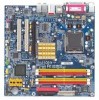
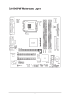
GA-8I945PMF Motherboard Layout COMA LPT KB_MS ATX_12V LGA775 CPU_FAN IT8712F RF_ID ATX COMB GA-8I945PMF USB USB 1394 LAN AUDIO1 AUDIO2 F_AUDIO PCIE_16 PCI1 Marvell 8053 PCI2 CD_IN PCIE_1 CODEC SPDIF_IO Intel 945P DDRII1 DDRII2 DDRII3 DDRII4 IDE FDD BIOS - Gigabyte GA-8I945PMF | Manual - Page 7
200/133MHz) Host Interface DDRII 667(Note)/533/400MHz DIMM Intel 945P GMCH Dual Channel Memory GMCHCLK (266/200/133MHz) 66MHz 33MHz 14.318MHz 48MHz BIOS 4 Serial ATAII Intel ) (Note) To use a DDRII 667 memory module on the motherboard, you must install an 800/1066MHz FSB processor . - 7 - - Gigabyte GA-8I945PMF | Manual - Page 8
- 8 - - Gigabyte GA-8I945PMF | Manual - Page 9
instructions below: 1. Please turn off the computer and unplug its power cord. 2. When handling the motherboard , avoid touching any metal leads or connectors. 3. It is best to wear an electrostatic discharge (ESD) cuff when handling electronic components (CPU motherboard problem manual - Gigabyte GA-8I945PMF | Manual - Page 10
therefore the actual memory size is less than the stated amount. For example, 4 GB of memory size will instead be shown as 3.xxGB memory during system startup. (Note 3) To use a DDRII 667 memory module on the motherboard, you must install an 800/1066MHz FSB processor . GA-8I945PMF Motherboard - 10 - Gigabyte GA-8I945PMF | Manual - Page 11
warning Š CPU smart fan control Š System smart fan control BIOS Š Use of licensed AWARD BIOS Š Supports Q-Flash Additional Features Š Supports @BIOS Š Supports EasyTune5 (only supports Hardware Monitor function) Overclocking Š Over Clock via BIOS (DDRII) Form Factor Š Micro ATX form - Gigabyte GA-8I945PMF | Manual - Page 12
the socket in a straight and downwards motion. Avoid twisting or bending motions that might cause damage to the CPU during installation.) GA-8I945PMF Motherboard - 12 - Fig. 4 Once the CPU is properly inserted, please replace the plastic covering and push the metal lever back into its original - Gigabyte GA-8I945PMF | Manual - Page 13
the CPU and make sure the push pins aim to the pin hole on the motherboard.Pressing down the push pins diagonally. Fig. 4 Please make sure the Male and Female push pin are joined closely. (for detailed installation instructions, please refer to the heatsink installation section of the user manual - Gigabyte GA-8I945PMF | Manual - Page 14
fit in one direction. Insert the DIMM memory module vertically into the DIMM socket. Then push it down. Fig.2 Close the plastic clip at both edges of the DIMM sockets to lock the DIMM module. Reverse the installation steps when you wish to remove the DIMM module. GA-8I945PMF Motherboard - 14 - - Gigabyte GA-8I945PMF | Manual - Page 15
English Dual Channel DDR II GA-8I945PMF supports the Dual Channel Technology. After operating the Dual Channel Technology, the bandwidth of Memory Bus will double. GA-8I945PMF includes 4 DIMM sockets, and each Channel has two DIMM sockets as following: Channel A : DDR II 1, DDR II 2 Channel B : - Gigabyte GA-8I945PMF | Manual - Page 16
outlined below: 1. Read the related expansion card's instruction document before install the expansion card into the computer. setup BIOS utility of expansion card from BIOS. 8. Install related driver from the operating system. Installing a PCI Express x 16 expansion GA-8I945PMF Motherboard - 16 - - Gigabyte GA-8I945PMF | Manual - Page 17
mouse, scanner, zip, speaker...etc. have a standard USB interface. Also make sure your OS supports USB controller. If your OS does not support USB controller, please contact OS vendor for possible patch or driver upgrade. For more information please contact your OS or device(s) vendors. LAN Port The - Gigabyte GA-8I945PMF | Manual - Page 18
for detailed software configuration information. 1-7 Connectors Introduction 1 3 17 2 9 11 14 1) ATX_12V 2) ATX (Power Connector) 3) CPU_FAN 4) SYS_FAN 5) FDD 6) IDE 7) SATAII0_1 / SATAII2_3 8) F_PANEL 9) F_AUDIO GA-8I945PMF Motherboard 4 13 5 6 7 18 15 16 12 10 8 10) PWR_LED 11) CD_IN 12 - Gigabyte GA-8I945PMF | Manual - Page 19
proper location on the motherboard and connect tightly. The ATX_12V power connector mainly supplies power to the CPU. If the ATX_12V power start. If you use a 24-pin ATX power supply, please remove the small cover on the power connector on the motherboard before plugging in the power cord ; Otherwise - Gigabyte GA-8I945PMF | Manual - Page 20
failure. Caution! Please remember to connect the power to the CPU fan to prevent CPU overheating and failure. 1 CPU_FAN 1 SYS_FAN Pin No. 1 supported are: 360KB, 720KB, 1.2MB, 1.44MB and 2.88MB. Please connect the red power connector wire to the pin1 position. 34 33 GA-8I945PMF Motherboard 2 - Gigabyte GA-8I945PMF | Manual - Page 21
the other as Slave (for information on settings, please refer to the instructions located on the IDE device). 40 39 2 1 7) SATAII0/SATAII1/ rate. Please refer to the BIOS setting for the Serial ATA and install the proper driver in order to work properly. Pin No. Definition 1 GND 7 1 2 TXP - Gigabyte GA-8I945PMF | Manual - Page 22
1: Power Pin 2- Pin 3: NC Pin 4: Data(-) Open: Normal Close: Reset Hardware System Open: Normal Close: Power On/Off Pin 1: LED anode(+) Pin 2: LED cathode(-) NC GA-8I945PMF Motherboard - 22 - - Gigabyte GA-8I945PMF | Manual - Page 23
Out (R) 6 NC 7 NC 8 No Pin 9 Line Out (L) 10 NC By default, the audio driver is configured to support HD Audio. To connect an AC97 front panel audio module to this connector, please refer to the instructions on Page 65 about the software settings. 10) PWR_LED PWR_LED is connect with the - Gigabyte GA-8I945PMF | Manual - Page 24
your local dealer. The GREEN_USB connector provides no standby power when system is off and it does not support USB device to wake up from S3 mode. Users who wish to shut down the standby power ( (example: optical mouses) will not light on during system power-off. GA-8I945PMF Motherboard - 24 - - Gigabyte GA-8I945PMF | Manual - Page 25
English 13) F1_1394/F2_1394 (IEEE 1394 Connector) Serial interface standard set by Institute of Electrical and Electronics Engineers, which has features like high speed, highbandwidth and hot plug. Be careful with the polarity of the IEEE1394 connector. Check the pin assignment carefully while you - Gigabyte GA-8I945PMF | Manual - Page 26
this jumper. To clear CMOS, temporarily short 1-2 pin. Default doesn't include the "Shunter" to prevent from improper use this jumper. 1 Open: Normal 1 Short :Clear CMOS GA-8I945PMF Motherboard - 26 - - Gigabyte GA-8I945PMF | Manual - Page 27
assignments before you connect the external device cable. Please contact your nearest dealer for the optional GIGABYTE external device. Pin No. Definition 1 Power 1 2 RFID_RI- 3 RF_TXD 4 RF_RXD 5 used batteries according to the manufacturer's instructions. - 27 - Hardware Installation - Gigabyte GA-8I945PMF | Manual - Page 28
English GA-8I945PMF Motherboard - 28 - - Gigabyte GA-8I945PMF | Manual - Page 29
configuration in the CMOS SRAM of the motherboard. When the power is turned off, the battery on the motherboard supplies the necessary power to the CMOS to its original settings. If you wish to upgrade to a new BIOS, either Gigabyte's Q-Flash or @BIOS utility can be used. Q-Flash allows the user to - Gigabyte GA-8I945PMF | Manual - Page 30
auto detect Temperature, voltage, fan, speed. „ Frequency / Voltage Control This setup page is control CPU clock and frequency ratio. „ Load Fail-Safe Defaults Fail-Safe Defaults indicates the value of the to limit access to the system and Setup, or just to Setup. GA-8I945PMF Motherboard - 30 - - Gigabyte GA-8I945PMF | Manual - Page 31
English „ Set User Password Change, set, or disable password. It allows you to limit access to the system. „ Save & Exit Setup Save CMOS value settings to CMOS and exit setup. „ Exit Without Saving Abandon all CMOS value changes and exit setup. - 31 - BIOS Setup - Gigabyte GA-8I945PMF | Manual - Page 32
[None] [None] Change the day, month, year Drive A Drive B Floppy 3 Mode Suport Holt On Base Memory Extended Memory Total Memory [1.44M, 3.5"] [None] [Disabled] [All, But Keyboard] 640K 127M 128M Sun. to Sat. -time clock. For example, 1 p.m. is 13:00:00. GA-8I945PMF Motherboard - 32 - - Gigabyte GA-8I945PMF | Manual - Page 33
detection step and allow for faster system start up. Manual User can manually input the correct settings Access Mode Use this to set 3.5" 3.5 inch double-sided drive; 2.88M byte capacity. Floppy 3 Mode Support (for Japan Area) Disabled Normal Floppy Drive. (Default value) Drive A Drive - Gigabyte GA-8I945PMF | Manual - Page 34
on the motherboard, or 640K for systems with 640K or more memory installed on the motherboard. Extended Memory The BIOS determines how much extended memory is present during the POST. This is the amount of memory located above 1 MB in the CPU's memory address map. GA-8I945PMF Motherboard - 34 - Gigabyte GA-8I945PMF | Manual - Page 35
Third Boot Device Password Check # CPU Hyper-Threading Limit CPUID Max. to 3 No-Execute Memory Protect (Note) CPU Enhanced Halt (C1E) (Note) CPU Thermal Monitor 2(TM2) (Note) CPU EIST Function (Note) [Press will show up when you install a processor which supports this function. - 35 - BIOS Setup - Gigabyte GA-8I945PMF | Manual - Page 36
. (Default value) Disable CPU Thermal Monitor 2 (TM2) function. CPU EIST Function (Note) Enabled Enable CPU EIST function. (Default value) Disabled Disable EIST function. (Note) This item will show up when you install a processor which supports this function. GA-8I945PMF Motherboard - 36 - - Gigabyte GA-8I945PMF | Manual - Page 37
Port 1/3 Set to USB Controller USB 2.0 Controller USB Keyboard Support USB Mouse Support Azalia Codec Onboard H/W 1394 Onboard H/W LAN Onboard LAN Boot ROM to 4 HDDs on the motherboard; 2 for SATA and the other for PATA IDE. Set On-Chip SATA mode to Enhanced, the motherboard allows up to 6 HDDs - Gigabyte GA-8I945PMF | Manual - Page 38
Keyboard Support Enabled Enable USB Keyboard Support. Disabled Disable USB Keyboard Support. (Default value) USB Mouse Support Enabled Disabled Enable USB Mouse Support. Disable USB Mouse Support. is 278/IRQ5. Enable onboard LPT port and address is 3BC/IRQ7. GA-8I945PMF Motherboard - 38 - - Gigabyte GA-8I945PMF | Manual - Page 39
English Parallel Port Mode SPP Using Parallel port as Standard Parallel Port. (Default value) EPP Using Parallel port as Enhanced Parallel Port. ECP Using Parallel port as Extended Capabilities Port. ECP+EPP Using Parallel port as ECP & EPP mode. ECP Mode Use DMA 3 Set ECP Mode Use DMA to - Gigabyte GA-8I945PMF | Manual - Page 40
) : (0~59) Power On By Mouse Disabled Disable this function. (Default value) Double Click Double click on PS/2 mouse left button to power on the system. GA-8I945PMF Motherboard - 40 - - Gigabyte GA-8I945PMF | Manual - Page 41
system, the system will be in "Off" state. Full-On (Default value) When AC-power back to the system, the system always in "On" state. Memory When AC-power back to the system, the system will return to the Last state before AC-power off. - 41 - BIOS Setup - Gigabyte GA-8I945PMF | Manual - Page 42
) Set IRQ 3,4,5,7,9,10,11,12,14,15 to PCI 1. Auto assign IRQ to PCI 2. (Default value) Set IRQ 3,4,5,7,9,10,11,12,14,15 to PCI 2. GA-8I945PMF Motherboard - 42 - - Gigabyte GA-8I945PMF | Manual - Page 43
Vcore DDRV +3.3V +12V Current System Temperature Current CPU Temperature Current CPU FAN Speed Current SYSTEM FAN Speed System Warning Temperature CPU Warning Temperature CPU FAN Fail Warning SYSTEM FAN Fail Warning CPU Smart FAN Control CPU Smart FAN Mode System Smart FAN Control [Disabled] Yes - Gigabyte GA-8I945PMF | Manual - Page 44
. With such CPU fans, selecting PWM will not effectively reduce the fan speed. System Smart FAN Control Disabled Disable this function. Enabled When this function is enabled, System fan will run at different speed depending on System temperature. (Default Value) GA-8I945PMF Motherboard - 44 - Gigabyte GA-8I945PMF | Manual - Page 45
CPU Clock Ratio System Memory Multiplier Memory Memory Frequency = Host clock X 2.5. Auto Set Memory frequency by DRAM SPD data. (Default value) Memory Frequency (Mhz) The values depend on "System Memory Multiplier" item. (Note) This item will show up when you install a processor which supports - Gigabyte GA-8I945PMF | Manual - Page 46
Item F10: Save & Exit Setup Load Optimized Defaults Selecting this field loads the factory defaults for BIOS and Chipset Features which the system automatically detects. GA-8I945PMF Motherboard - 46 - - Gigabyte GA-8I945PMF | Manual - Page 47
English 2-10 Set Supervisor/User Password CMOS Setup Utility-Copyright (C) 1984-2005 Award Software ` Standard CMOS Features ` Advanced BIOS Features ` Integrated Peripherals ` Power Management Setup ` PnP/PCI ConfigurationEsnter Password: ` PC Health Status ` Frequency/Voltage Control Load Fail - Gigabyte GA-8I945PMF | Manual - Page 48
Item F10: Save & Exit Setup Abandon all Data Type "Y" will quit the Setup Utility without saving to RTC CMOS. Type "N" will return to Setup Utility. GA-8I945PMF Motherboard - 48 - - Gigabyte GA-8I945PMF | Manual - Page 49
Pictures below are shown in Windows XP. Insert the driver CD-title that came with your motherboard into your CD-ROM drive, the driver CD-title will auto start and show the installation guide. If not, please double click the CD-ROM device icon in "My computer", and execute the Run.exe. 3-1 Install - Gigabyte GA-8I945PMF | Manual - Page 50
Software Applications This page displays all the tools that Gigabyte developed and some free software, you can choose anyone you want and press "install" to install them. 3-3 Driver CD Information This page lists the contents of software and drivers in this CD-title. GA-8I945PMF Motherboard - 50 - - Gigabyte GA-8I945PMF | Manual - Page 51
English 3-4 Hardware Information This page lists all device you have for this motherboard. 8I945PMF F2 3-5 Contact Us Please see the last page for details. - 51 - Install Drivers - Gigabyte GA-8I945PMF | Manual - Page 52
English GA-8I945PMF Motherboard - 52 - - Gigabyte GA-8I945PMF | Manual - Page 53
model support these Motherboard Intelligent Tweaker) Motherboard Intelligent Tweaker (M.I.T.) allows user to access and change BIOS feature settings with relative speed and ease. Through GIGABYTE the CPU system bus, memory timings or to enabled Gigabyte's well as the latest drivers for their system. - Gigabyte GA-8I945PMF | Manual - Page 54
the current functions status 9. GIGABYTE Logo Log on to GIGABYTE website 10. Help button Display EasyTuneTM 5 Help file 11. Exit or Minimize button Quit or Minimize EasyTuneTM 5 software (Note) EasyTune 5 functions may vary depending on different motherboards. GA-8I945PMF Motherboard - 54 - - Gigabyte GA-8I945PMF | Manual - Page 55
: 1. Intel x86 platforms 2. At least 64M bytes of system memory 3. VESA-supported VGA cards How to use the Xpress Recovery2 Initial access by booting CD-ROM. Save the settings and exit the BIOS Setup. Insert the provided driver CD into your CD-ROM drive. Upon system restart, the message which says - Gigabyte GA-8I945PMF | Manual - Page 56
motherboards (As this is a BIOS-related issue, it can be solved by BIOS update) GA-K8U GA-K8U-9 GA-K8NXP-SLI GA-K8N Ultra-SLI GA-K8N Pro-SLI GA-K8NXP-9 GA-K8N Ultra-9 GA-K8NF-9 (PCB Ver. 1.0) GA-K8NE (PCB Ver. 1.0) GA-K8NMF-9 GA-8N-SLI Royal GA-8N-SLI Pro GA-8N-SLI GA-8I945PMF Motherboard - Gigabyte GA-8I945PMF | Manual - Page 57
of Gigabyte motherboards are equipped with dual BIOS. In the BIOS menu of the motherboards supporting Q-Flash and Dual BIOS, the Q-Flash utility and Dual BIOS utility are combined in the same screen. This section only deals with how to use Q-Flash utility. In the following sections, we take GA-8KNXP - Gigabyte GA-8I945PMF | Manual - Page 58
: Contains the names of four actions needed to operate the Q-Flash/Dual BIOS utility. Pressing the buttons mentioned on your keyboards to perform these actions. GA-8I945PMF Motherboard - 58 - - Gigabyte GA-8I945PMF | Manual - Page 59
BIOS using the Q-Flash utility. As described in the "Before you begin" section above, you must prepare a floppy disk having the BIOS file for your motherboard and insert it to your computer. If you have already put the floppy disk into your system and have entered the Q-Flash utility, please follow - Gigabyte GA-8I945PMF | Manual - Page 60
: Intel Pentium(R) 4 1.6GHz (133x12) Memory Testing : 131072K OK Memory Frequency 266 MHz in Single Channel Primary Master : FUJITSU MPE3170AT ED-03-08 Primary Slave / Q-Flash / F9 For Xpress Recovery 09/23/2003-i875P-6A79BG03C-00 GA-8I945PMF Motherboard - 60 - - Gigabyte GA-8I945PMF | Manual - Page 61
Press Y on your keyboard to save and exit. Part Two: Updating BIOS with Q-FlashTM Utility on Single-BIOS Motherboards. This part guides users of single-BIOS motherboards how to update BIOS using the Q-FlashTM utility. CMOS Setup Utility-Copyright (C) 1984-2004 Award Software Standard CMOS Features - Gigabyte GA-8I945PMF | Manual - Page 62
the "Before you begin" section above, you must prepare a floppy disk having the BIOS file for your motherboard and insert it to your computer. If you have already put the floppy disk into your system and have not take out the floppy disk when it begins flashing BIOS. GA-8I945PMF Motherboard - 62 - - Gigabyte GA-8I945PMF | Manual - Page 63
8GE800 F4 Check System Health OK Main Processor : Intel Pentium(R) 4 1.7GHz (100x17.0) Memory Testing : 122880K OK + 8192K Shared Memory Primary Master : FUJITSU MPE3170AT ED-03-08 Primary Slave : None Secondary Master : CREATIVEDVD-RM DVD1242E BC101 Secondary Slave - Gigabyte GA-8I945PMF | Manual - Page 64
the @BIOS utility Fig 2. Installation Complete and Run @BIOS Click Sart/ Programs/ GIGABYTE/@BIOS Select @BIOS item than click Install Fig 3. The @BIOS Utility Fig 4. any other methods (such as: 8I945PMF.F2). e. Complete update process following the instruction. GA-8I945PMF Motherboard - 64 - - Gigabyte GA-8I945PMF | Manual - Page 65
. It means to save the current BIOS version. IV. Check out supported motherboard and Flash ROM: In the very beginning, there is "About this program motherboard's. Otherwise, your system won't boot. III. In method I, if the BIOS file you need cannot be found in @BIOSTM server, please go onto Gigabyte - Gigabyte GA-8I945PMF | Manual - Page 66
driver, you should find an Audio Manager icon in your system tray (you can also find the icon in Control Panel). Double-click the icon to open the Audio Control Panel. STEP 2: In the Audio Control Panel, click the Audio I/O tab. In the upper left list, click 2CH Speaker. GA-8I945PMF Motherboard - Gigabyte GA-8I945PMF | Manual - Page 67
Line Out depending on the device connected and click OK. The 2-channel audio setup is completed. 4 Channel Audio Setup STEP 1 : After installation of the audio driver, you should find an Audio Manager icon in your system tray (you can also find the icon in Control Panel). Double-click the icon to - Gigabyte GA-8I945PMF | Manual - Page 68
6-channel audio setup is completed. 8 Channel Audio Setup STEP 1 : After installation of the audio driver, you should find an Audio Manager icon in your system tray (you can also find the icon in Control Panel). Double-click the icon to open the Audio Control Panel. GA-8I945PMF Motherboard - 68 - - Gigabyte GA-8I945PMF | Manual - Page 69
: At the Sound Effect menu, users can adjust sound option settings as desired. AC'97 Audio Configuration: To enable the front panel audio connector to support AC97 Audio mode, go to the Audio Control Panel and click the Audio I/O tab. In the ANALOG area, click the Tool icon and then select - Gigabyte GA-8I945PMF | Manual - Page 70
Troubleshooting Below is a collection of general asked questions. To check general asked questions based on a specific motherboard model, please log on to http://www.gigabyte steps in the manual. If your board problems. memory bad Continuous short beeps: Power error GA-8I945PMF Motherboard - 70 - - Gigabyte GA-8I945PMF | Manual - Page 71
- 71 - Appendix English - Gigabyte GA-8I945PMF | Manual - Page 72
English GA-8I945PMF Motherboard - 72 - - Gigabyte GA-8I945PMF | Manual - Page 73
- 73 - Appendix English - Gigabyte GA-8I945PMF | Manual - Page 74
English GA-8I945PMF Motherboard - 74 - - Gigabyte GA-8I945PMF | Manual - Page 75
- 75 - Appendix English - Gigabyte GA-8I945PMF | Manual - Page 76
English GA-8I945PMF Motherboard - 76 - - Gigabyte GA-8I945PMF | Manual - Page 77
- 77 - Appendix English - Gigabyte GA-8I945PMF | Manual - Page 78
English GA-8I945PMF Motherboard - 78 - - Gigabyte GA-8I945PMF | Manual - Page 79
.giga-byte.com U.S.A. G.B.T. INC. TEL: +1-626-854-9338 FAX: +1-626-854-9339 Tech. Support : http://tw.giga-byte.com/TechSupport/ServiceCenter.htm Non-Tech. Support(Sales/Marketing) : http://ggts.gigabyte.com.tw/nontech.asp WEB address : http://www.giga-byte.com Germany G.B.T. TECHNOLOGY TRADING GMBH - Gigabyte GA-8I945PMF | Manual - Page 80
.gigabyte.cz Romania Representative Office Of GIGA-BYTE Technology Co., Ltd. in Romania Tech. Support : http://tw.giga-byte.com/TechSupport/ServiceCenter.htm Non-Tech. Support(Sales/Marketing) : http://ggts.gigabyte.com.tw/nontech.asp WEB address: http://www.gigabyte.com.ro GA-8I945PMF Motherboard
-
 1
1 -
 2
2 -
 3
3 -
 4
4 -
 5
5 -
 6
6 -
 7
7 -
8
-
9
-
10
-
11
-
12
-
13
-
14
-
15
-
16
-
17
-
18
-
19
-
20
-
21
-
22
-
23
-
24
-
25
-
26
-
27
-
28
-
29
-
30
-
31
-
32
-
33
-
34
-
35
-
36
-
37
-
38
-
39
-
40
-
41
-
42
-
43
-
44
-
45
-
46
-
47
-
48
-
49
-
50
-
51
-
52
-
53
-
54
-
55
-
56
-
57
-
58
-
59
-
60
-
61
-
62
-
63
-
64
-
65
-
66
-
67
-
68
-
69
-
70
-
71
-
72
-
73
-
74
-
75
-
76
-
77
-
78
-
79
-
80
 |
 |

GA-8I945PMF
Intel
®
Pentium
®
D / Pentium
®
4 LGA775 Processor Motherboard
User's Manual
Rev. 1003
12ME-8I945PMF-1003
*
The WEEE marking on the product indicates this product must not be disposed of with user's other household waste
and must be handed over to a designated collection point for the recycling of waste electrical and electronic equipment!!
*
The WEEE marking applies only in European Union's member states.