Gigabyte GA-8IP775 Manual
Gigabyte GA-8IP775 Manual
 |
View all Gigabyte GA-8IP775 manuals
Add to My Manuals
Save this manual to your list of manuals |
Gigabyte GA-8IP775 manual content summary:
- Gigabyte GA-8IP775 | Manual - Page 1
GA-8IP775 Series Intel® Pentium® 4 LGA775 Processor Motherboard User's Manual Rev. 1003 12ME-8IP775-1003 - Gigabyte GA-8IP775 | Manual - Page 2
Motherboard GA-8IP775/GA-8IP775-G Sep. 10, 2004 Motherboard GA-8IP775/GA-8IP775-G Sep. 10, 2004 - Gigabyte GA-8IP775 | Manual - Page 3
product information and specifications, please carefully read the "Product User Manual". „ For detailed information related to Gigabyte's unique features, please go to Gigabyte's website under "Technology Guide" where information can be downloaded in .pdf format. For more product details, please - Gigabyte GA-8IP775 | Manual - Page 4
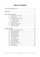
Table of Contents GA-8IP775(-G) Motherboard Layout 6 Block Diagram ...7 Chapter 1 Hardware Installation 9 1-1 Memory 14 1-5 Installation of Expansion Cards 16 1-6 I/O Back Panel Introduction 17 1-7 Connectors Introduction 18 Chapter 2 BIOS Setup 29 The Main Menu (For example: BIOS - Gigabyte GA-8IP775 | Manual - Page 5
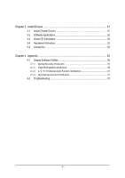
Chipset Drivers 51 3-2 Software Applications 52 3-3 Driver CD Information 52 3-4 Hardware Information 53 3-5 Contact Us ...53 Chapter 4 Appendix 55 4-1 Unique Software Utilities 55 4-1-1 Xpress Recovery Introduction 55 4-1-2 Flash BIOS Method Introduction 58 4-1-3 2 / 4 / 6 / 8 Channel Audio - Gigabyte GA-8IP775 | Manual - Page 6
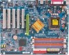
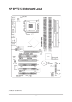
GA-8IP775(-G) Motherboard Layout KB_MS CPU_FAN ATX_12V COMA FDD ATX COMB LPT R_USB LGA775 IDE1 IDE2 GA-8IP775(-G) DDR1 DDR2 USB LAN (*) AUDIO CD_IN Intel® 865P Marvell F_AUDIO 8001 (*) AGP DDR4 DDR3 IT8712 CODEC SUR_CEN DUAL CHANNEL DDR PCI1 SATA P4 Titan PCI2 CI IR_CIR - Gigabyte GA-8IP775 | Manual - Page 7
8X/4X AGPCLK (66MHz) 5 PCI RJ45 (*) Marvell 8001(*) AC97 Link LGA775 Processor CPUCLK+/- (200/133MHz) System Bus 800/533MHz DDR Intel 865P 266/333/400MHz ZCLK (66MHz) HCLK+/- (200/133MHz) 66MHz 33 MHz 48 MHz 14.318 MHz BIOS ICH5 LPC BUS IT8712 24 MHz Game Port Floppy LPT Port PCICLK - Gigabyte GA-8IP775 | Manual - Page 8
- 8 - - Gigabyte GA-8IP775 | Manual - Page 9
of violating the conditions recommended in the user manual. 3. Damage due to improper installation. 4. Damage due to use of uncertified components. 5. Damage due to use exceeding the permitted parameters. 6. Product determined to be an unofficial Gigabyte product. - 9 - Hardware Installation - Gigabyte GA-8IP775 | Manual - Page 10
Peripherals Onboard LAN (*) Onboard Audio w GA-8IP775 Series Motherboard: GA-8IP 775-G/GA-8 IP775 w Supports the latest Intel® Pentium® 4 LGA775 CPU w Supports 800/533MHz FSB w L2 cache varies with CPU w Northbridge: Intel® 865P w Southbridge: Intel® ICH5 w 4 DDR DIMM memory slots (supports up to - Gigabyte GA-8IP775 | Manual - Page 11
temperature w CPU / Systemfan failure warning w CPU sm art fan control w Use of licensed AWARD BIOS w Supports Q-Flash w Supports @BIOS w Supports EasyTune w Over Voltage via BIOS (CPU/DDR/AGP) w Over Clock via BIOS (CPU/DDR/AGP/PCI) w ATX form factor; 30.5cm x 24.4cm - 11 - Hardware Installation - Gigabyte GA-8IP775 | Manual - Page 12
CPU: An Intel® Pentium 4 Processor with HT Technology - Chipset: An Intel® Chipset that supports HT Technology - BIOS: A BIOS that supports HT Technology CPU during installation.) GA-8IP775 Series Motherboard - 12 - Fig. 4 Once the CPU is properly inserted, please replace the plastic covering and - Gigabyte GA-8IP775 | Manual - Page 13
the m ale push pin doesn't face inwards before installation. (This instruction is only for Intel boxed fan) Fig. 3 Place the heatsink atop the CPU and joined closely. (for detailed installation instructions, please refer to the heatsink installation section of the user manual) Fig. 5 Please check - Gigabyte GA-8IP775 | Manual - Page 14
in one direction. Insert the DIM M memory module vertically into the DIMM socket. Then push it down. Fig.2 Close the plastic clip at both edges of the DIMM sockets to lock the DIMM module. Reverse the installation steps when you wish to remove the DIMM module. GA-8IP775 Series Motherboard - 14 - - Gigabyte GA-8IP775 | Manual - Page 15
English Dual Cha nnel DDR GA-8IP775 series supports the Dual Channel Technology. After operating the Dual Channel Technology, the bandwidth of Memory Bus will add double up to 6.4GB/s. GA-8IP775 series includes 4 DIMM sockets, and each Channel has two DIMM sockets as following: Channel A : DDR 1, - Gigabyte GA-8IP775 | Manual - Page 16
below: 1. Read the related expansion card's instruction document before install the expansion card into the com Replace your computer's chassis cover. 7. Power on the computer, if necessary, setup BIOS utility of expansion card from BIOS. 8. Install related driver GA-8IP775 Series Motherboard - 16 - - Gigabyte GA-8IP775 | Manual - Page 17
USB controller. If your OS does not support USB controller, please contact OS vendor for possible patch or driver upgrade. For m ore inform ation please contact your OS or device(s)vendors. LAN Port (*) The provided Internet connection is Gigabit Ethernet, providing data transfer speeds of 10/100 - Gigabyte GA-8IP775 | Manual - Page 18
8) PWR_LED 9) F_PANEL 10) F_AUDIO 11) SUR_CEN 12) CD_IN 13) SPDIF_IO 14) IR_CIR 15) F_USB1/F_USB2 16) GAME 17) INFO_LINK 18) CI 19) CLR_CMOS 20) BAT GA-8IP775 Series Motherboard - 18 - - Gigabyte GA-8IP775 | Manual - Page 19
required power, the result can lead to an unstable system or a system that is unable to start. Please remove the sticker on the motherboard before plugging in while theATX power supplier is 24 pins; Otherwise, please do not remove it. Pin No. Definition 1 GND 3 4 2 GND 1 2 3 +12V 4 +12V - Gigabyte GA-8IP775 | Manual - Page 20
IDE devices, please set the jumper on one IDE device as Master and the other as Slave (for information on settings, please refer to the instructions located on the IDE device). 40 39 2 1 GA-8IP775 Series Motherboard - 20 - - Gigabyte GA-8IP775 | Manual - Page 21
of the cable connects to the FDD drive. The types of FDD drives supported are: 360KB, 720KB, 1.2MB, 1.44MB and 2.88MB. Please connect can provide 150MB/s transfer rate. Please refer to the BIOS setting for the Serial ATA and install the proper driver in order to work properly. Pin No. Definition - Gigabyte GA-8IP775 | Manual - Page 22
2- Pin 3: NC Pin 4: Data(-) Open:Normal Operation Close: Reset Hardware System Open:Normal Operation Close:Power On/Off Pin 1: LED anode(+) Pin 2: LED cathode(-) NC GA-8IP775 Series Motherboard - 22 - - Gigabyte GA-8IP775 | Manual - Page 23
the MB header. To find out if the chassis you are buying support front audio connector, please contact your dealer.Please note, you can have the alternative of using front audio connector or of using rear audio connector to play sound. 2 1 10 9 Pin No. 1 2 3 4 5 6 7 8 9 10 Definition MIC GND - Gigabyte GA-8IP775 | Manual - Page 24
GND 4 CD-R 13) SPDIF_IO (SPDIF In/Out) The SPDIF output is capable of providing digital audio to external speakers or compressed AC3 data to an external Dolby Digital Decoder. Use this feature only when . 1 2 3 4 5 6 Definition VCC No Pin SPDIF SPDIFI GND GND GA-8IP775 Series Motherboard - 24 - - Gigabyte GA-8IP775 | Manual - Page 25
English 14) IR_CIR Make sure the pin 1 on the IR device is aling with pin one the connector. To enable the IR/CIR function on the board, you are required to purchase an option IR/CIR module. To use IR function only, please connect IR module to Pin1 to Pin5. Be careful with the polarity of the IR/ - Gigabyte GA-8IP775 | Manual - Page 26
English 16) GAME (GAME Connector) This connector supports joystick, MIDI keyboard and other relate audio devices. Pin No. Definition 1 VCC 2 GRX1_R 3 GND 2 16 4 GPSA2 5 VCC 5 6 7 8 9 10 Definition SMBCLK VCC SMBDATA GPIO GND GND No Pin NC +12V +12V GA-8IP775 Series Motherboard - 26 - - Gigabyte GA-8IP775 | Manual - Page 27
English 18) CI (Chassis Intrusion, Case Open) This 2-pin connector allows your system to enable or disable the "Case Open" item in BIOS, if the system casebegin remove. Pin No. Definition 1 1 Signal 2 GND 19) CLR_CMOS (Clear CMOS) You may clear the CMOS data to its default values by - Gigabyte GA-8IP775 | Manual - Page 28
of used batteries according to the manufacturer's instructions. If you want to erase CM OS... 1.Turn OFF the computer and unplug the power cord. 2.Remove the battery, wait for 30 second. 3.Re-install the battery. 4.Plug the power cord and turn ON the computer. GA-8IP775 Series Motherboard - 28 - - Gigabyte GA-8IP775 | Manual - Page 29
a new BIOS, either Gigabyte's Q-Flash or @BIOS utility can be used. Q-Flash allows the user to quickly and easily update or backup BIOS without entering the operating system. @BIOS is a Windows-based utility that does not require users to boot to DOS before upgrading BIOS but directly download and - Gigabyte GA-8IP775 | Manual - Page 30
Flash Load Fail-Safe Defaults Load Optimized Defaults Set Supervisor Password Set User Password Save & Exit Setup Exit Without Saving KLJI: Select Item includes all the items in standard compatible BIOS. „ Advanced BIOS Features This setup page includes all the GA-8IP775 Series Motherboard - 30 - - Gigabyte GA-8IP775 | Manual - Page 31
English „ Set Supervisor Password Change, set, or disable password. It allows you to limit access to the system and Setup, or just to Setup. „ Set User Password Change, set, or disable password. It allows you to limit access to the system. „ Save & Exit Setup Save CMOS value settings to CMOS and - Gigabyte GA-8IP775 | Manual - Page 32
Jan. to Dec. Holt On Base Memory Extended Memory Total Memory [All, But Keyboard] 640K 127M 128M - Gigabyte GA-8IP775 | Manual - Page 33
88M byte capacity. Floppy 3 Mode Support (for Japan Area) Disabled Normal memory is typically 512K for systems with 512K memory installed on the motherboard, or 640K for systems with 640K or more memory installed on the motherboard. Extended Memory The BIOS determines how much extended memory - Gigabyte GA-8IP775 | Manual - Page 34
Software Advanced BIOS Features X detect automatically and show up when you install the Intel® Pentium® 4 processor with HT Technology. Hard Disk Boot Priority Select boot priority by USB-HDD. LAN Select your boot device priority by LAN. Disabled Select your GA-8IP775 Series Motherboard - 34 - - Gigabyte GA-8IP775 | Manual - Page 35
Enabled Enables CPU Hyper Threading Feature. Please note that this feature is only working Disabled for operating system with multi processors mode supported. (Default value) Disables CPU Hyper Threading. Limit CPUID Max. to 3 Enabled Disabled Limit CPUID Maximum value to 3 when use older - Gigabyte GA-8IP775 | Manual - Page 36
SATA Port1 Configure as USB Controller USB 2.0 Controller USB Keyboard Support USB Mouse Support AC97 Audio Onboard H/W LAN (*) Onboard LAN Boot ROM (*) Onboard Serial Port 1 Onboard Serial Port 2 Disable onboard 2nd channel IDE port. (*) Only for GA-8IP775-G. GA-8IP775 Series Motherboard - 36 - - Gigabyte GA-8IP775 | Manual - Page 37
H/W LAN function. (Default value) Disabled Disable this function. Onboard LAN Boot ROM (*) This function decide whether to invoke the boot ROM of the onboard LAN chip. Disabled Disable this function. (Default Value) Enabled Enable this function. (*) Only for GA-8IP775-G. - 37 - BIOS Setup - Gigabyte GA-8IP775 | Manual - Page 38
port 1 and address is 2E8. Disabled Disable onboard Serial port 1. Onboard Serial Port 2 Auto BIOS will automatically setup the port 2 address. 3F8/IRQ4 2F8/IRQ3 Enable onboard Serial port 2 and DMA to 3. (Default value) 1 Set ECP Mode Use DMA to 1. GA-8IP775 Series Motherboard - 38 - - Gigabyte GA-8IP775 | Manual - Page 39
320. Disabled Disable this function. (Default value) CIR Port IRQ 5 Set CIR Port IRQ to 5. 11 Set CIR Port IRQ to 11. (Default value) - 39 - BIOS Setup - Gigabyte GA-8IP775 | Manual - Page 40
under ACPI OS [S3] Set suspend type to Suspend to RAM under ACPI OS KLJI: Move Enter: Select F5: Previous LAN can awake the system from any suspend state. Disabled Disable Modem Ring on/wake on Lan function. Enabled Enable Modem Ring on/wake on Lan. (Default value) GA-8IP775 Series Motherboard - Gigabyte GA-8IP775 | Manual - Page 41
On password. AC Back Function Soft-Off When AC-power back to the system, the system will be in "Off" state. (Default value) Full-On Memory When AC-power back to the system, the system always in "On" state. When AC-power back to the system, the system will return to - Gigabyte GA-8IP775 | Manual - Page 42
3. PCI 4 IRQ Assignment Auto Auto assign IRQ to PCI 4. (Default value) 3,4,5,7,9,10,11,12,14,15 Set IRQ 3,4,5,7,9,10,11,12,14,15 to PCI 4. GA-8IP775 Series Motherboard - 42 - - Gigabyte GA-8IP775 | Manual - Page 43
/ 194oF. Disabled Disable this function. (Default value) CPU/SYSEM FAN Fail Warning Disabled Fan warning function disable. (Default value) Enabled Fan warning function enable. - 43 - BIOS Setup - Gigabyte GA-8IP775 | Manual - Page 44
to the CPU FAN that you used. 3 PIN Set CPU FAN PIN Type to 3 pin. (Default value) 4 PIN Set CPU FAN PIN Type to 4 pin. GA-8IP775 Series Motherboard - 44 - - Gigabyte GA-8IP775 | Manual - Page 45
CPU Host Frequency (Mhz) x AGP/PCI/SRC Fixed Memory Frequency For Memory Frequency (Mhz) AGP/PCI/SRC Frequency (Mhz) DIMM you use FSB800 Pentium 4 processor, please set "CPU Host Frequency" to 200MHz. Incorrect using it may cause your system broken. For power End-User use only! AGP/PCI/ - Gigabyte GA-8IP775 | Manual - Page 46
to the memory may occur. For power End-User use only! AGP Supports adjustable CPU Vcore from 0.8375V to 1.6000V. (Default value: Normal) Warning: CPU may be damaged or reduce CPU life-cycle when CPU is over-voltage. Normal CPU Vcore Display your CPU Vcore Voltage. GA-8IP775 Series Motherboard - Gigabyte GA-8IP775 | Manual - Page 47
Standard CMOS Features ` Advanced BIOS Features ` Integrated Peripherals ` Optimized Defaults Set Supervisor Password Set User Password Load Fail-Safe DefaultsS(aYv/ CMOS Features ` Advanced BIOS Features ` Integrated Peripherals Set Supervisor Password Set User Password Load Optimized DefaultsS(aYve - Gigabyte GA-8IP775 | Manual - Page 48
Advance BIOS Features Menu, you will be prompted for the password every time the system is rebooted or any time you try to enter Setup Menu. If you select "Setup" at "Password Check" in Advance BIOS Features Menu, you will be prompted only when you try to enter Setup. GA-8IP775 Series Motherboard - Gigabyte GA-8IP775 | Manual - Page 49
Setup Save & Exit Setup Type "Y" will quit the Setup Utility and save the user setup value to RTC CMOS. Type "N" will return to Setup Utility. 2-12 Exit (C) 1984-2004 Award Software ` Standard CMOS Features ` Advanced BIOS Features ` Integrated Peripherals ` Power Management Setup ` PnP/PCI - Gigabyte GA-8IP775 | Manual - Page 50
English GA-8IP775 Series Motherboard - 50 - - Gigabyte GA-8IP775 | Manual - Page 51
in Windows XP. Insert the driver CD-title that came with your motherboard into your CD-ROM drive, the driver CD-title will auto start and show the installation guide. If not, please double click the CD-ROM device icon in "My computer", and execute the setup.exe. 3-1 Install Chipset Drivers This - Gigabyte GA-8IP775 | Manual - Page 52
English 3-2 Software Applications This page displays all the tools that Gigabyte developed and some free software. 3-3 Driver CD Information This page lists the contents of software and drivers in this CD-title. GA-8IP775 Series Motherboard - 52 - - Gigabyte GA-8IP775 | Manual - Page 53
English 3-4 Hardware Information This page lists all device you have for this motherboard. 3-5 Contact Us Please see the last page for details. - 53 - Install Drivers - Gigabyte GA-8IP775 | Manual - Page 54
English GA-8IP775 Series Motherboard - 54 - - Gigabyte GA-8IP775 | Manual - Page 55
, the user can restore the drive to its original state. 1. Supports FAT16, FAT32 BIOS menu, select "Advanced BIOS Feature" and set to boot from CD-ROM. Insert the provided driver CD into your CD drive, then save and exit the BIOS V1.0 (C) Copy Right 2003. GIGABYTE Technology CO. , Ltd. 1. Execute - Gigabyte GA-8IP775 | Manual - Page 56
as well as drive reading/writing speed will affect backup speed. 3. It is recommended that Xpress Recovery be immediately installed after OS and all required driver and software installations are complete. GA-8IP775 Series Motherboard - 56 - - Gigabyte GA-8IP775 | Manual - Page 57
Esc to Exit The backup utility will automatically scan your system and back up data as a backup image in your hard drive. Not all systems support access to Xpress Recovery by pressing the F9 key during computer power on. If this is the case, please use the boot from CD-ROM - Gigabyte GA-8IP775 | Manual - Page 58
first. 1. Download the latest BIOS for your motherboard from Gigabyte's website. 2. Extract the BIOS file downloaded and save the BIOS file (the one with model name.Fxx. For example, 8KNXPU.Fba) to a floppy disk. 3. Reboot your PC and press Del to enter BIOS menu. The BIOS upgrading guides below are - Gigabyte GA-8IP775 | Manual - Page 59
Setup PnP/PCI Configurations PC Health Status MB Intelligent Tweaker(M.I.T.) ESC: Quit F8: Dual BIOS/Q-Flash Select Language Load Fail-Safe Defaults Load Optimized Defaults Set Supervisor Password Set User Password Save & Exit Setup Exit Without Saving F3: Change Language F10: Save & Exit Setup - Gigabyte GA-8IP775 | Manual - Page 60
Save Main BIOS to Floppy Save Backup BIOS to Floppy Enter : Run :Move ESC:Reset F10:Power Off Do not trun off power or reset your system at this stage!! After BIOS file is read, you'll see a confirmation dialog box asking you "Are you sure to update BIOS?" GA-8IP775 Series Motherboard - 60 - Gigabyte GA-8IP775 | Manual - Page 61
Ally Copyright (C) 1984-2003, Award Software, Inc. Intel i875P AGPset BIOS for 8KNXP Ultra Fba Check System Health OK , VCore = 1.5250 Main Processor : Intel Pentium(R) 4 1.6GHz (133x12) Memory Testing : 131072K OK Memory Frequency 266 MHz in Single Channel Primary - Gigabyte GA-8IP775 | Manual - Page 62
Updating BIOS with Q-FlashTM Utility on Single-BIOS Motherboards. This part guides users of single-BIOS motherboards how to update BIOS using the User Password Save & Exit Setup Exit Without Saving F3: Change Language F10: Save & Exit Setup Time, Date, Hard Disk Type... GA-8IP775 Series Motherboard - Gigabyte GA-8IP775 | Manual - Page 63
file you want to flash and press Enter. In this example, we only download one BIOS file to the floppy disk so only one BIOS file, 8GE800.F4, is listed. Please confirm again you have the correct BIOS file for your motherboard. Q-Flash Utility V1.30 Flash Type/Size SST 49LF002A 256K 8GE800.F4Keep - Gigabyte GA-8IP775 | Manual - Page 64
03/18/2003-I845GE-6A69YG01C-00 6. Press Del to enter BIOS menu after system reboots and "Load BIOS Fail-Safe Defaults". See how to Load BIOS Fail-Safe Defaults, please kindly refer to Step 6 to 7 in Part One. Congratulation!! You have updated BIOS successfully!! GA-8IP775 Series Motherboard - 64 - - Gigabyte GA-8IP775 | Manual - Page 65
allows users to update their BIOS under Windows. Just select the desired @BIOS server to download the latest version of BIOS. Fig 1. Installing the @BIOS utility Fig 2. Installation Complete and Run @BIOS Select @BIOS item than click Install Click Sart/ Programs/ GIGABYTE/@BIOS Fig 3. The @BIOS - Gigabyte GA-8IP775 | Manual - Page 66
won't boot. III. In method I, if the BIOS file you need cannot be found in @BIOSTM server, please go onto Gigabyte's web site for downloading and updating it according to method II. IV. Please note that any interruption during updating will cause system unbooted GA-8IP775 Series Motherboard - 66 - - Gigabyte GA-8IP775 | Manual - Page 67
4 / 6 / 8 Channel Audio Function Introduction The installation of windows 98SE/2K/ME/XP is very simple. Please follow next the stereo speakers or earphone to "Line Out". STEP 2 : Following installation of the audio driver, you find a icon a Sound Effect icon on the lower right hand taskbar. Click - Gigabyte GA-8IP775 | Manual - Page 68
to "Line Out", the rear channels to "Line In". STEP 2 : Following installation of the audio driver, you find a icon a Sound Effect icon on the lower right hand taskbar. Click the icon to bar and select "4CH Speaker" to complete 4 channel audio configuration. GA-8IP775 Series Motherboard - 68 - - Gigabyte GA-8IP775 | Manual - Page 69
"Line Out",the rear channels to "Line In", and the Center/Subwoofer channels to "MIC In". MIC In Line Out STEP 2 : Following installation of the audio driver, you find a icon a Sound Effect icon on the lower right hand taskbar. Click the icon to select the function. Line In STEP 3 : Click "Speaker - Gigabyte GA-8IP775 | Manual - Page 70
the front channels to the "LINE OUT" port located on the audio panel and the rear channels to the Surround-Kit "REAR R/L" port. Connect the center/subwoofer channels to the Surround-Kit "SUB CENTER" and the R/L channels to the Surround-Kit "SUR BACK" port. GA-8IP775 Series Motherboard - 70 - - Gigabyte GA-8IP775 | Manual - Page 71
(This method requires UAJ function) STEP 4 : Following installation of the audio driver, you find a icon a Sound Effect icon on the lower right hand 8CH Speaker" to complete 8 channel audio configuration. Sound Effect Configuration: At the sound effect menu, users can adjust sound option settings as - Gigabyte GA-8IP775 | Manual - Page 72
Output Device (Optional Device) A "SPDIF output" device is available on the motherboard. Cable with rear bracket is provided and could link to the "SPDIF , and fix it with screw. 2. Connect SPDIF device to the motherboard. 3. Connect SPDIF to the SPDIF decoder. GA-8IP775 Series Motherboard - 72 - - Gigabyte GA-8IP775 | Manual - Page 73
version before to enable Jack-Sensing support for Windows 98/98SE/2000/ME. Jack-Sensing includes 2 parts: AUTO and MANUAL. Following is an example for 2 channels (Windows XP): Introduction of audio connectors You may connect CDROM, Walkman or others audio input devices to Line In jack, speakers - Gigabyte GA-8IP775 | Manual - Page 74
jack (Line-in/ Line-out). That means users do not need to worry the audio device should be plug in Line-in or Line-out jack, the device will work perfectly after UAJ is activated. Enable UAJ function: You can click "UAJ Automatic" button to enable UAJ function. GA-8IP775 Series Motherboard - 74 - - Gigabyte GA-8IP775 | Manual - Page 75
Troubleshooting Below is a collection of general asked questions. To check general asked questions based on a specific motherboard model, please log on to http://tw.giga-byte.com/faq/faq.htm Question 1: I cannot see some options that were included in previous BIOS after updating BIOS the manual. If - Gigabyte GA-8IP775 | Manual - Page 76
memory failure 4 beeps Timer not operational 5 beeps Processor error 6 beeps 8042 - gate A20 failure 7 beeps Processor exception interrupt error 8 beeps Display memory 9 short: BIOS ROM error Continuous long beeps: DRAM error Continuous short beeps: Power error GA-8IP775 Series Motherboard - 76 - - Gigabyte GA-8IP775 | Manual - Page 77
- 77 - Appendix English - Gigabyte GA-8IP775 | Manual - Page 78
English GA-8IP775 Series Motherboard - 78 - - Gigabyte GA-8IP775 | Manual - Page 79
Milton Keynes, MK1 1DR, UK, England TEL: +44-1908-362700 FAX: +44-1908-362709 Tech. Support : http://uk.giga-byte.com/TechSupport/ServiceCenter.htm Non-Tech. Support(Sales/Marketing) : http://ggts.gigabyte.com.tw/nontech.asp WEB address : http://uk.giga-byte.com The Netherlands GIGA-BYTE TECHNOLOGY - Gigabyte GA-8IP775 | Manual - Page 80
www.gigabyte.ru Poland Representative Office Of Giga-Byte Technology Co., Ltd. POLAND Tech. Support : http://tw.giga-byte.com/TechSupport/ServiceCenter.htm Non-Tech. Support(Sales/Marketing) : http://ggts.gigabyte.com.tw/nontech.asp WEB address : http://www.gigabyte.pl GA-8IP775 Series Motherboard
-
 1
1 -
 2
2 -
 3
3 -
 4
4 -
 5
5 -
 6
6 -
 7
7 -
8
-
9
-
10
-
11
-
12
-
13
-
14
-
15
-
16
-
17
-
18
-
19
-
20
-
21
-
22
-
23
-
24
-
25
-
26
-
27
-
28
-
29
-
30
-
31
-
32
-
33
-
34
-
35
-
36
-
37
-
38
-
39
-
40
-
41
-
42
-
43
-
44
-
45
-
46
-
47
-
48
-
49
-
50
-
51
-
52
-
53
-
54
-
55
-
56
-
57
-
58
-
59
-
60
-
61
-
62
-
63
-
64
-
65
-
66
-
67
-
68
-
69
-
70
-
71
-
72
-
73
-
74
-
75
-
76
-
77
-
78
-
79
-
80
 |
 |

GA-8IP775 Series
Intel
®
Pentium
®
4 LGA775 Processor Motherboard
User's Manual
Rev. 1003
12ME-8IP775-1003