Gigabyte GA-8IPE775-G Manual
Gigabyte GA-8IPE775-G Manual
 |
View all Gigabyte GA-8IPE775-G manuals
Add to My Manuals
Save this manual to your list of manuals |
Gigabyte GA-8IPE775-G manual content summary:
- Gigabyte GA-8IPE775-G | Manual - Page 1
)/4X(1.5V) mode AGP slot, but they support 2X (3.3V) only. The GA-8IPE775 Series (or any AGP 4X/8X only) motherboards might not function properly, If you install this card in it. Note : Although Gigabyte's AG32S(G) graphics card is based on ATi Rage 128 Pro chip, the design of AG32S(G) is compliance - Gigabyte GA-8IPE775-G | Manual - Page 2
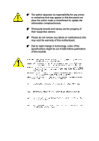
may appear in this document nor does the author make a commitment to update the information contained herein. 0 Third-party brands and names are the owners. 0 Please do not remove any labels on motherboard, this may void the warranty of this motherboard. 0 Due to rapid change in technology, some of - Gigabyte GA-8IPE775-G | Manual - Page 3
Mother Board GA-8IPE775 Pro/GA-8IPE775-G/GA-8IPE775 May 14, 2004 - Gigabyte GA-8IPE775-G | Manual - Page 4
Industry, CA 91748 Phone/Fax No: (818) 854-9338/ (818) 854-9339 hereby declares that the product Product Name: Motherboard Model Number: GA-8IPE775 Pro/GA-8IPE775-G /GA-8IPE775 Conforms to the following specifications: FCC Part 15, Subpart B, Section 15.107(a) and Section 15.109 (a),Class B Digital - Gigabyte GA-8IPE775-G | Manual - Page 5
GA-8IPE775 Series Intel® Pentium® 4 Socket 775 Processor Motherboard USER'S MANUAL Pentium® 4 Processor Motherboard Rev. 1004 12ME-8IPE775-1004 - Gigabyte GA-8IPE775-G | Manual - Page 6
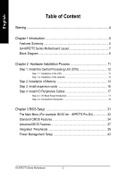
I/O Back Panel Introduction 17 Step 4-2: Connectors Introduction 19 Chapter 3 BIOS Setup 31 The Main Menu (For example: BIOS Ver. : 8IPE775 Pro.D4 32 Standard CMOS Features 34 Advanced BIOS Features 37 Integrated Peripherals 39 Power Management Setup 43 GA-8IPE775 Series Motherboard - 2 - - Gigabyte GA-8IPE775-G | Manual - Page 7
Set Supervisor/User Password 51 Save & Exit Setup 52 Exit Without Saving 52 Chapter 4 Technical Reference 53 Flash BIOS Method Introduction 53 2- / 4- / 6- / 8- Channel Audio Function Introduction 67 Jack-Sensing and UAJ Introduction 73 Xpress Recovery2 Introduction 75 Chapter 5 Appendix 79 - Gigabyte GA-8IPE775-G | Manual - Page 8
the motherboard PCB surface, because the circuit wire may be near by the hole. Be careful, don't let the screw contact any printed circuit write or parts on the PCB that are near the fixing hole, otherwise it may damage the board or cause board malfunctioning. GA-8IPE775 Series Motherboard - 4 - - Gigabyte GA-8IPE775-G | Manual - Page 9
Features Summary CPU Motherboard Chipset Memory Slots On-Board IDE On-Board Floppy On-Board Peripherals y Supports the latest Intel® Pentium® 4 Socket 775 CPU y Supports 533/800MHz FSB y L2 cache varies with CPU y GA-8IPE775 Series Motherboard: GA-8IPE775 Pro/GA-8IPE775-G/GA-8IPE775 y North Bridge - Gigabyte GA-8IPE775-G | Manual - Page 10
Dual BIOS /Q-Flash y Supports EasyTune y Supports @BIOS y Supports CPU Smart Fan Control function y Over Voltage (DDR/AGP/CPU) by BIOS y Over Clock (DDR/AGP/CPU/PCI) by BIOS y ATX size form factor; 30.5cm x 24.4cm Only for GA-8IPE775 Pro. Only for GA-8IPE775-G. GA-8IPE775 Series Motherboard - Gigabyte GA-8IPE775-G | Manual - Page 11
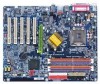
GA-8IPE775 Series Motherboard Layout COMA KB_MS ATX_12V CPU_FAN FDD LPT ATX COMB IDE1 IDE2 GA-8IPE775 (Pro/-G) DDR1 DDR2 R_USB SOCKET 775 LAN USB AUDIO MAIN PCI5 BIOS BACKUP BIOS F2_1394 F1_1394 F_PANEL F_USB2 PWR_LED F_USB1 Only for GA-8IPE775 Pro. Only for GA-8IPE775-G. - 7 - Gigabyte GA-8IPE775-G | Manual - Page 12
) HCLK+/- (200MHz) 66MHz 33 MHz 48 MHz 14.318 MHz Dual BIOS AC97 Link ICH5 LPC BUS IT8712 24 MHz Game Port Floppy LPT Port for GA-8IPE775 Pro. Only for GA-8IPE775-G. CLK GEN ZCLK (66MHz) CPUCLK+/- (200MHz) AGPCLK (66MHz) HCLK+/- (200MHz) ICH3V66 (66MHz) GA-8IPE775 Series Motherboard - - Gigabyte GA-8IPE775-G | Manual - Page 13
- 9 - Introduction English - Gigabyte GA-8IPE775-G | Manual - Page 14
English GA-8IPE775 Series Motherboard - 10 - - Gigabyte GA-8IPE775-G | Manual - Page 15
computer, you must complete the following steps: Step 1- Install the Central Processing Unit (CPU) Step 2- Install memory modules Step 3- Install expansion cards Step 4- Install I/O Peripherals to the power outlet. Continue with the BIOS/software installation. - 11 - Hardware Installation Process - Gigabyte GA-8IPE775-G | Manual - Page 16
the small gold colored triangle located on the edge of the CPU socket. Align the indented corner of the CPU with the triangle and gently insert the CPU into position. GA-8IPE775 Series Motherboard - 12 - Fig. 4 Once the CPU is properly inserted, please replace the plastic covering and push the - Gigabyte GA-8IPE775-G | Manual - Page 17
instructions, please refer to the heat sink installation section of the user manual) Fig. 3 Please attach the power connector of the heatsink to the CPU fan header located on the motherboard make sure that the memory used is supported by the motherboard. It is recommended that memory of similar - Gigabyte GA-8IPE775-G | Manual - Page 18
English The motherboard supports DDR memory modules, whereby BIOS will automatically detect memory capacity and specifications. Memory modules are designed so that they DRAM subsystem that are suitable for servers, workstations, and full range of desktop PCs. GA-8IPE775 Series Motherboard - 14 - - Gigabyte GA-8IPE775-G | Manual - Page 19
English GA-8IPE775 Series supports the Dual Channel Technology. After operating the Dual Channel Technology, the bandwidth of Memory Bus will add double up to 6.4GB/s. GA-8IPE775 Series includes 4 DIMM sockets, and each Channel has two DIMM sockets as following: Channel A : DIMM 1, DIMM 2 Channel B - Gigabyte GA-8IPE775-G | Manual - Page 20
computer's chassis cover. 7. Power on the computer, if necessary, setup BIOS utility of expansion card from BIOS. 8. Install related driver from the operating system. AGP Card Please carefully pull out the small card is locked by the small white- drawable bar. GA-8IPE775 Series Motherboard - 16 - - Gigabyte GA-8IPE775-G | Manual - Page 21
standard PS/2 keyboard and PS/2 mouse. Parallel Port, Serial Port and VGA Port (LPT/COMA/COMB) Parallel Port (25 pin Female) This connector supports 2 standard COM ports and 1 Parallel port. Device like printer can be connected to Parallel port; mouse and modem etc can be connected to Serial - Gigabyte GA-8IPE775-G | Manual - Page 22
channel function you can refer to page 24, and contact your nearest dealer for optional SUR_CEN cable. If you want the detail information for 2-/4-/6-/8-channel audio setup installation, please refer to page 67. Only for GA-8IPE775 Pro. Only for GA-8IPE775-G. GA-8IPE775 Series Motherboard - 18 - - Gigabyte GA-8IPE775-G | Manual - Page 23
) SPDIF_IO 14) IR_CIR 15) F_USB1/F_USB2 16) GAME 17) INFO_LINK 18) F1_1394 19) F2_1394 20) SATA0/SATA1 21) CI 22) CLR_CMOS 23) BAT Only for GA-8IPE775 Pro. - 19 - Hardware Installation Process - Gigabyte GA-8IPE775-G | Manual - Page 24
location on the motherboard and connect tightly. The ATX_12V power connector mainly supplies power to the CPU. If the ATX_12V the sticker on the motherboard before plugging in while the ATX power supplier is 24pins; Otherwise, please do not remove it. GA-8IPE775 Series Motherboard 13 24 13 1 - Gigabyte GA-8IPE775-G | Manual - Page 25
cooler to prevent system overheating and failure. Caution! Please remember to connect the power to the CPU fan to prevent CPU overheating and failure. 1 CPU_FAN 1 SYS_FAN Pin No. 1 2 3 4 Definition GND Pin1. 40 39 Only for GA-8IPE775 Pro. 2 IDE2 1 IDE1 - 21 - Hardware Installation Process - Gigabyte GA-8IPE775-G | Manual - Page 26
7) FDD (Floppy Connector) Please connect the floppy drive ribbon cables to FDD. It supports 360K, 1.2M, 720K, 1.44M and 2.88M bytes floppy disk types. The red stripe power LED will turn to another color. Pin No. Definition 1 MPD+ 1 2 MPD- 3 MPD- GA-8IPE775 Series Motherboard - 22 - - Gigabyte GA-8IPE775-G | Manual - Page 27
English 9) F_PANEL (2 x 10 pins Connector) Please connect the power LED, PC speaker, reset switch and power switch etc. of your chassis front panel to the F_PANEL connector according to the pin assignment below. Speaker Connector Power Switch 20 19 SPEAK- SPEAK+ Reset Switch PW- PW+ MSG- MSG+ - Gigabyte GA-8IPE775-G | Manual - Page 28
Audio (R) Reserved No Pin Front Audio (L) Rear Audio (L) 11) SUR_CEN (Surround Center Connector) Please contact your nearest dealer for optional SUR_CEN cable. 12 78 Pin No. 1 2 3 4 5 6 7 8 Definition SUR OUTL SUR OUTR GND No Pin CENTER_OUT BASS_OUT AUX_L AUX_R GA-8IPE775 Series Motherboard - Gigabyte GA-8IPE775-G | Manual - Page 29
to the connector. 1 Pin No. Definition 1 CD-L 2 GND 3 GND 4 CD-R 13) SPDIF_IO (SPDIF In/Out Connector) The SPDIF output is capable of providing digital audio to external speakers or compressed AC3 data to an external Dolby Digital Decoder. Use this feature only when your stereo system has - Gigabyte GA-8IPE775-G | Manual - Page 30
IR device is aling with pin one the connector. To enable the IR/CIR function on the board, you are required to purchase an option IR/CIR module. To use IR function only, please 7 8 9 10 Definition Power Power USB DxUSB DyUSB Dx+ USB Dy+ GND GND No Pin NC GA-8IPE775 Series Motherboard - 26 - - Gigabyte GA-8IPE775-G | Manual - Page 31
English 16) GAME (GAME Connector) This connector supports joystick, MIDI keyboard and other relate audio devices. Pin No. Definition 1 VCC 2 GRX1_R 3 GND 4 GPSA2 2 16 5 VCC 6 GPX2_R 7 GPY2_R 1 15 8 MSI_R 9 GPSA1 10 GND 11 GPY1_R 12 VCC 13 GPSB1 14 MSO_R - Gigabyte GA-8IPE775-G | Manual - Page 32
cable, please contact your local dealer. Only for GA-8IPE775 Pro. Pin No. Definition 1 Power 2 Power 3 TPA0+ 2 16 4 TPA0- 5 GND 6 GND 1 15 7 TPB0+ 8 TPB0- 9 Power 10 Power 11 TPA1+ 12 TPA1- 13 GND 14 No Pin 15 TPB1+ 16 TPB1- GA-8IPE775 Series Motherboard - 28 - - Gigabyte GA-8IPE775-G | Manual - Page 33
7 1 4 GND 5 RXN 6 RXP 7 GND 21) CI (Chassis Intrusion, Case Open) This 2-pin connector allows your system to enable or disable the "Case Open" item in BIOS, if the system case begin remove. Pin No. Definition 1 1 Signal 2 GND - 29 - Hardware Installation Process - Gigabyte GA-8IPE775-G | Manual - Page 34
: Clear CMOS 23) BAT (BATTERY) GA-8IPE775 Series Motherboard CAUTION Danger of explosion if battery is incorrectly replaced. Replace only with the same or equivalent type recommended by the manufacturer. Dispose of used batteries according to the manufacturer's instructions. If you want to erase - Gigabyte GA-8IPE775-G | Manual - Page 35
BIOS, either Gigabyte's Q-Flash or @BIOS utility can be used. Q-Flash allows the user to quickly and easily update or backup BIOS without entering the operating system. @BIOS is a Windows-based utility that does not require users to boot to DOS before upgrading BIOS but directly download and update - Gigabyte GA-8IPE775-G | Manual - Page 36
page includes all the items in standard compatible BIOS. z Advanced BIOS Features This setup page includes all the items of Award special enhanced features. z Integrated Peripherals This setup page includes all onboard peripherals. Only for GA-8IPE775 Pro. GA-8IPE775 Series Motherboard - 32 - - Gigabyte GA-8IPE775-G | Manual - Page 37
System auto detect Temperature, voltage, fan, speed. z Frequency/Voltage Control This setup page is control CPU's clock and frequency ratio. z Load Fail-Safe Defaults Fail-Safe Defaults indicates the value of the z Exit Without Saving Abandon all CMOS value changes and exit setup. - 33 - BIOS Setup - Gigabyte GA-8IPE775-G | Manual - Page 38
Setup Utility-Copyright (C) 1984-2004 Award Software Standard CMOS Features Mon, r > 1999 to 2098 KLJI: Move Enter: Select F5: Previous Values +/-/PU/PD: Value F10: Save ESC week, from Sun to Sat, determined by the BIOS and is display only The month, Jan. GA-8IPE775 Series Motherboard - 34 - - Gigabyte GA-8IPE775-G | Manual - Page 39
Device Setup. You can use one of three methods: Auto None Allows BIOS to automatically detect IDE devices during POST(default) Select this if no the system will skip the automatic Manual detection step and allow for faster system start up. User can manually input the correct settings Access Mode - Gigabyte GA-8IPE775-G | Manual - Page 40
Support motherboard, or 640 K for systems with 640 K or more memory installed on the motherboard. Extended Memory The BIOS determines how much extended memory is present during the POST. This is the amount of memory located above 1MB in the CPU's memory address map. GA-8IPE775 Series Motherboard - Gigabyte GA-8IPE775-G | Manual - Page 41
Features CMOS Setup Utility-Copyright (C) 1984-2004 Award Software Advanced BIOS Features X Hard Disk Boot Priority First Boot Device Second Boot Device Third Boot Device Password Check Boot to OS2 or DR-DOS # CPU Hyper-Threading Limit CPUID Max. to 3 [Press Enter] [Floppy] [Hard Disk] [CDROM - Gigabyte GA-8IPE775-G | Manual - Page 42
system with multi processors mode supported. (Default value) Disabled Disables CPU Hyper Threading. Limit CPUID Max. to 3 Enabled Disabled Limit CPUID Maximum value to 3 when use older OS like NT4. (Default value) Disables CPUID Limit for windows XP. GA-8IPE775 Series Motherboard - 38 - - Gigabyte GA-8IPE775-G | Manual - Page 43
USB Keyboard Support USB Mouse Support AC97 Audio Onboard H/W 1394 1 Onboard H/W LAN 12 Onboard LAN Boot ROM F5: Previous Values +/-/PU/PD: Value F10: Save ESC: Exit F6: Fail-Save Default F7: Optimized Defaults F1: General Help Only for GA-8IPE775 Pro. Only for GA-8IPE775-G. - 39 - BIOS - Gigabyte GA-8IPE775-G | Manual - Page 44
or IDE2, SATA controller will remap to IDE controller. (Default value) Manual Set SATA Mode manually. SATA Port0 Configure as IDE Pri. Master IDE Pri. Slave Remap Support Enabled Disabled Enable USB Keyboard Support. Disable USB Keyboard Support. (Default value) GA-8IPE775 Series Motherboard - Gigabyte GA-8IPE775-G | Manual - Page 45
) Enable onboard Serial port 2 and address is 3E8. 2E8/IRQ3 Disabled Enable onboard Serial port 2 and address is 2E8. Disable onboard Serial port 2. Only for GA-8IPE775 Pro. Only for GA-8IPE775-G. - 41 - BIOS Setup - Gigabyte GA-8IPE775-G | Manual - Page 46
Port Mode This feature allows you to connect with an advanced printer via the port mode it supports. SPP Using Parallel port as Standard Parallel Port. (Default value) EPP Using Parallel port as Port Address to 330. Disable this function. (Default value) GA-8IPE775 Series Motherboard - 42 - - Gigabyte GA-8IPE775-G | Manual - Page 47
value) Power Management Setup CMOS Setup Utility-Copyright (C) 1984-2004 Award Software Power Management Setup ACPI Suspend Type Power LED in S1 state ACPI OS [S3] Set suspend type to Suspend to RAM under ACPI OS KLJI: Move Enter: Select F5: Previous Values +/-/PU/PD: Value F10: Save ESC: - Gigabyte GA-8IPE775-G | Manual - Page 48
other client server on the LAN can awake the system from any suspend state. Disabled Disable Modem Ring on/wake on Lan function. Enabled Enable Modem Ring on/wake on Lan. (Default value) Resume by ) and press Enter to set the Keyboard Power On password. GA-8IPE775 Series Motherboard - 44 - - Gigabyte GA-8IPE775-G | Manual - Page 49
off. PnP/PCI Configurations CMOS Setup Utility-Copyright (C) 1984-2004 Award Software PnP/PCI Configurations PCI 1/PCI 5 IRQ Assignment PCI 2 Auto] [Auto] [Auto] Item Help Menu Level` KLJI: Move Enter: Select F5: Previous Values +/-/PU/PD: Value F10: Save ESC: Exit F6: Fail- - BIOS Setup - Gigabyte GA-8IPE775-G | Manual - Page 50
3V / +12V Detect system's voltage status automatically. Current CPU Temperature Detect CPU Temp. automatically. Current CPU/POWER /SYSTEM FAN Speed (RPM) Detect CPU/POWER/SYSTEM Fan speed status automatically. Only for GA-8IPE775 Pro. Only for GA-8IPE775-G. GA-8IPE775 Series Motherboard - 46 - - Gigabyte GA-8IPE775-G | Manual - Page 51
, CPU fan will run at high speed. c. When the CPU temperature is between 40 and 50 degrees Celsius, CPU fan will run at medium speed. d. When the CPU temperature is lower than 40 degrees Celsius, CPU fan will run at low speed. Only for GA-8IPE775 Pro. Only for GA-8IPE775-G. - 47 - BIOS Setup - Gigabyte GA-8IPE775-G | Manual - Page 52
, please set "CPU Clock" to 100MHz.If you use FSB533 Pentium 4 processor, please set "CPU Clock" to 133MHz. If you use FSB800 Pentium 4 processor, please set "CPU Clock" to 200MHz. Incorrect using it may cause your system broken. For power End-User use only! GA-8IPE775 Series Motherboard - 48 - - Gigabyte GA-8IPE775-G | Manual - Page 53
. Auto Set Memory frequency by DRAM SPD data. (Default value) Memory Frequency (Mhz) The values depend on CPU Host Frequency(Mhz). AGP/PCI/SRC Frequency (Mhz) The values depend on Fixed AGP/PCI/SRC Fixed. DIMM . But it may damage to AGP Card when enable this feature. - 49 - BIOS Setup - Gigabyte GA-8IPE775-G | Manual - Page 54
DefaultSs a(vYe/N&)?ENxit Setup Exit Without Saving KLJI: Select Item F10: Save & Exit Setup Load Optimized Defaults Selecting this field loads the factory defaults for BIOS and Chipset Features which the system automatically detects. Only for GA-8IPE775 Pro. GA-8IPE775 Series Motherboard - 50 - - Gigabyte GA-8IPE775-G | Manual - Page 55
BIOS Features Menu, you will be prompted for the password every time the system is rebooted or any time you try to enter Setup Menu. If you select "Setup" at "Password Check" in Advance BIOS Features Menu, you will be prompted only when you try to enter Setup. Only for GA-8IPE775 Pro. - 51 - BIOS - Gigabyte GA-8IPE775-G | Manual - Page 56
Exit Without Saving CMOS Setup Utility-Copyright (C) 1984-2004 Award Software ` Standard CMOS Features ` Advanced BIOS Features ` Integrated Peripherals ` Power Management Setup ` PnP/ RTC CMOS. Type "N" will return to Setup Utility. Only for GA-8IPE775 Pro. GA-8IPE775 Series Motherboard - 52 - - Gigabyte GA-8IPE775-G | Manual - Page 57
Set User Password ` PnP/PCI Configurations Enter Dual BIOS/Q-Flash UStialivtye (&YE/Nx)i?t SYetup ` PC Health Status Exit Without Saving ` Frequency/Voltage Control ESC: Quit F8: Dual BIOS1/Q-Flash KLJI: Select Item F10: Save & Exit Setup Only for GA-8IPE775 Pro. - 53 - Technical Reference - Gigabyte GA-8IPE775-G | Manual - Page 58
BIOS. Boot From : Main BIOS(Default), Backup BIOS Status 1: The user can set to boot from main BIOS or Backup BIOS. Status 2: If one of the main BIOS or the Backup BIOS fails, this item "Boot From : Main BIOS(Default)" will become gray and will not be changed by user. GA-8IPE775 Series Motherboard - Gigabyte GA-8IPE775-G | Manual - Page 59
Error : Disable(Default), Enable If the BIOS occurs a checksum error or the Main BIOS occurs a WIDE RANGE PROTECTION error and Halt On Error set to Enable, the PC will show messages on the boot screen, and the system will pause and wait for the user's instruction. If Auto Recovery :Disable, it will - Gigabyte GA-8IPE775-G | Manual - Page 60
.Fba) to a floppy disk. 3. Reboot your PC and press Del to enter BIOS menu. The BIOS upgrading guides below are separated into two parts. If your motherboard has dual-BIOS, please refer to Part One. If your motherboard has single-BIOS, please refer to Part Two. GA-8IPE775 Series Motherboard - 56 - - Gigabyte GA-8IPE775-G | Manual - Page 61
English Part One: Updating BIOS with Q-FlashTM Utility on Dual BIOS Motherboards. Some of Gigabyte motherboards are equipped with dual BIOS. In the BIOS menu of the motherboards supporting Q-Flash and Dual BIOS, the Q-Flash utility and Dual BIOS utility are combined in the same screen. This - Gigabyte GA-8IPE775-G | Manual - Page 62
in the Q-Flash menu and press Enter button. Later, you will see a box pop up showing the BIOS files you previously downloaded to the floppy disk. If you want to save the current BIOS for backup purpose, you can begin Step 1 with "Save Main BIOS to Floppy" item. GA-8IPE775 Series Motherboard - 58 - - Gigabyte GA-8IPE775-G | Manual - Page 63
flash and press Enter. In this example, we only download one BIOS file to the floppy disk so only one BIOS file, 8KNXPU.Fba, is listed. Please confirm again you have the correct BIOS file for your motherboard. Dual BIOS Utility Boot From Main Bios Main ROM Type/Size SST 49LF003A Backup ROM Type - Gigabyte GA-8IPE775-G | Manual - Page 64
Primary Master : FUJITSU MPE3170AT ED-03-08 Primary Slave : None Secondary Master : CREATIVEDVD-RM DVD1242E BC101 Secondary Slave : None Press DEL to enter SETUP / Dual BIOS / Q-Flash / F9 For Xpress Recovery 09/23/2003-i875P-6A79BG03C-00 GA-8IPE775 Series Motherboard - 60 - - Gigabyte GA-8IPE775-G | Manual - Page 65
F10: Save & Exit Setup Press Enter on your keyboard CMOS Setup Utility-Copyright (C) 1984-2003 Award Software ` Standard CMOS Features Top Performance ` Advanced BIOS Features Load Fail-Safe Defaults ` Integrated Peripherals Load Optimized Defaults ` Power Management Setup Set Supervisor - Gigabyte GA-8IPE775-G | Manual - Page 66
Single-BIOS Motherboards. This part guides users of single-BIOS motherboards how to update BIOS using the Q-Flash™ utility. Entering the Q-FlashTM utility: Step1: To use the Q-Flash utility, you must press Del in the boot screen to enter BIOS menu. CMOS Setup Utility-Copyright (C) 1984-2003 Award - Gigabyte GA-8IPE775-G | Manual - Page 67
this example, we only download one BIOS file to the floppy disk so only one BIOS file, 8GE800.F4, is listed. Please confirm again you have the correct BIOS file for your motherboard. Q-Flash Utility V1.30 Flash Type/Size SST 49LF003A 256K Keep DMI Data Enable Update BIOS from Floppy 8GE800.F4 - Gigabyte GA-8IPE775-G | Manual - Page 68
/18/2003-I845GE-6A69YG01C-00 6. Press Del to enter BIOS menu after system reboots and "Load BIOS Fail-Safe Defaults". See how to Load BIOS Fail-Safe Defaults, please kindly refer to Step 6 to 7 in Part One. Congratulation!! You have updated BIOS successfully!! GA-8IPE775 Series Motherboard - 64 - - Gigabyte GA-8IPE775-G | Manual - Page 69
Click "OK". (3) (4) Methods and steps: I. Update BIOS through Internet a. Click "Internet Update" icon b. Click "Update New BIOS" icon c. Select @BIOSTM sever d. Select the exact model name on your motherboard e. System will automatically download and update the BIOS. - 65 - Technical Reference - Gigabyte GA-8IPE775-G | Manual - Page 70
won't boot. c. In method I, if the BIOS file you need cannot be found in @BIOSTM server, please go onto Gigabyte's web site for downloading and updating it according to method II. d. Please note that any interruption during updating will cause system unbooted GA-8IPE775 Series Motherboard - 66 - - Gigabyte GA-8IPE775-G | Manual - Page 71
4- / 6- / 8- Channel Audio Function Introduction The installation of windows 98SE/2K/ME/XP is very simple. Please follow next the stereo speakers or earphone to "Line Out". STEP 2 : Following installation of the audio driver, you find a icon a Sound Effect icon on the lower right hand taskbar. Click - Gigabyte GA-8IPE775-G | Manual - Page 72
to "Line Out", the rear channels to "Line In". STEP 2 : Following installation of the audio driver, you find a icon a Sound Effect icon on the lower right hand taskbar. Click the icon to bar and select "4CH Speaker" to complete 4 channel audio configuration. GA-8IPE775 Series Motherboard - 68 - - Gigabyte GA-8IPE775-G | Manual - Page 73
Line Out", the rear channels to "Line In", and the Center/Subwoofer channels to "MIC In". MIC In Line Out STEP 2 : Following installation of the audio driver, you find a icon a Sound Effect icon on the lower right hand taskbar. Click the icon to select the function. Line In STEP 3 : Click "Speaker - Gigabyte GA-8IPE775-G | Manual - Page 74
the front channels to the "LINE OUT" port located on the audio panel and the rear channels to the Surround-Kit "REAR R/L" port. Connect the center/subwoofer channels to the Surround-Kit "SUB CENTER" and the R/L channels to the Surround-Kit "SUR BACK" port. GA-8IPE775 Series Motherboard - 70 - - Gigabyte GA-8IPE775-G | Manual - Page 75
panel and the R/L channels to the Surround-Kit "SUR BACK" port. (This method requires UAJ function) STEP 4 : Following installation of the audio driver, you find a icon a Sound Effect icon on the lower right hand taskbar. Click the icon to select the function. STEP 5 : Click "Speaker Configuration - Gigabyte GA-8IPE775-G | Manual - Page 76
Output Device (Optional Device) A "SPDIF output" device is available on the motherboard. Cable with rear bracket is provided and could link to the "SPDIF and fix it with screw. 2. Connect SPDIF device to the motherboard. 3. Connect SPDIF to the SPDIF decoder. GA-8IPE775 Series Motherboard - 72 - - Gigabyte GA-8IPE775-G | Manual - Page 77
version before to enable Jack-Sensing support for Windows 98/98SE/2000/ME. Jack-Sensing includes 2 parts: AUTO and MANUAL. Following is an example for 2 channels (Windows XP): Introduction of audio connectors You may connect CDROM, Walkman or others audio input devices to Line In jack, speakers - Gigabyte GA-8IPE775-G | Manual - Page 78
jack (Line-in/ Line-out). That means users do not need to worry the audio device should be plug in Line-in or Line-out jack, the device will work perfectly after UAJ is activated. Enable UAJ function: You can click "UAJ Automatic" button to enable UAJ function. GA-8IPE775 Series Motherboard - 74 - - Gigabyte GA-8IPE775-G | Manual - Page 79
backup and restoration of hard disk data. Supporting Microsoft operating systems including Windows XP/2000/NT/98/Me and DOS, and file After entering BIOS Setup, go to Advanced BIOS Feature and set to boot from CD-ROM. Save the settings and exit the BIOS Setup. Insert the provided driver CD into - Gigabyte GA-8IPE775-G | Manual - Page 80
this is a BIOS-related issue, it can be solved by BIOS update) GA-K8U GA-K8NXP-9 GA-K8U-9 GA-K8N Ultra-9 GA-K8NXP-SLI GA-K8NF-9 (PCB Ver. 1.0) GA-K8N Ultra-SLI GA-K8NE (PCB Ver. 1.0) GA-K8N Pro-SLI GA-K8NMF-9 GA-8IPE775 Series Motherboard - 76 - GA-8N-SLI Royal GA-8N-SLI Pro GA-8N-SLI - Gigabyte GA-8IPE775-G | Manual - Page 81
- 77 - Technical Reference English - Gigabyte GA-8IPE775-G | Manual - Page 82
English GA-8IPE775 Series Motherboard - 78 - - Gigabyte GA-8IPE775-G | Manual - Page 83
Drivers Pictures below are shown in Windows XP Insert the driver CD-title that came with your motherboard into your CD-ROM drive, the driver CD-title will auto start and show the installation guide driver manually or switch to the to install the drivers automatically. Massage: Some device drivers - Gigabyte GA-8IPE775-G | Manual - Page 84
100/1000 LAN chip use. „ RealTek AC97 Codec Driver For Intel(R) ICH/ICH2/ICH4/ICH5 AC97 audio. „ Intel USB 2.0 Driver It is recommended that you use the Microsoft Windows update for the most updated driver. For USB2.0 driver support under Windows XP operating system, please use Windows Service Pack - Gigabyte GA-8IPE775-G | Manual - Page 85
Microsoft DirectX 9 to enable 3D hardware acceleration that support for operating system to achieve better 3D performence. „ Marvell VCT Utility Utility for Marvell chips. [VCT(Virtual Cable Tester) Technology for Gigabit Networks] Only for GA-8IPE775 Pro. Only for GA-8IPE775-G. - 81 - Appendix - Gigabyte GA-8IPE775-G | Manual - Page 86
English SOFTWARE INFORMATION This page list the contects of softwares and drivers in this CD title. HARDWARE INFORMATION This page lists all device you have for this motherboard. CONTACT US Please see the last page for details. GA-8IPE775 Series Motherboard - 82 - - Gigabyte GA-8IPE775-G | Manual - Page 87
of general asked questions. To check general asked questions based on a specific motherboard model, please log on to http://tw.giga-byte.com/faq/faq.htm Question 1: I cannot see some options that were included in previous BIOS after updating BIOS. Why? Answer: Some advanced options are hidden in new - Gigabyte GA-8IPE775-G | Manual - Page 88
problems. However, they are only for reference purposes. The situations might differ from case to case. AMI BIOS error 11 beeps Cache memory bad AWARD BIOS Beep Codes 1 short: System BIOS ROM error Continuous long beeps: DRAM error Continuous short beeps: Power error GA-8IPE775 Series Motherboard - Gigabyte GA-8IPE775-G | Manual - Page 89
trouble during boot up, please follow the troubleshooting procedures . START Turn off the power and unplug the AC power cable, then remove all of the add-on cards and cables from motherboard. Please make sure motherboard Check if the CPU cooling fan attached to CPU properly. ls CPU cooling fan power - Gigabyte GA-8IPE775-G | Manual - Page 90
your problem, please contact with your local retailer or national distributor for help. Or, you could submit your question to the service mail via Gigabyte website technical support zone (http://www.gigabyte.com.tw). The appropriate response will be provided ASAP. GA-8IPE775 Series Motherboard - Gigabyte GA-8IPE775-G | Manual - Page 91
/Lot Number: BIOS version: O.S./A.S.: Hardware Mfs. Model name Size: Configuration CPU Memory Brand Video Card Audio Card HDD CD-ROM / DVD-ROM Modem Network AMR / CNR Keyboard Mouse Power supply Other Device Phone No.: PCB revision: Driver/Utility: Problem Description: - 87 - Gigabyte GA-8IPE775-G | Manual - Page 92
BIOS CPU CMOS CRIMM CNR DMA DMI DIMM DRM DRAM DDR ECP ESCD ECC EMC EPP ESD FDD FSB HDD IDE IRQ Meaning Advanced Configuration and Power Interface Advanced Power Management Accelerated Graphics Port Audio Channel Enhanced Interrupt Request to be continued...... GA-8IPE775 Series Motherboard - 88 - - Gigabyte GA-8IPE775-G | Manual - Page 93
English Acronyms IOAPIC ISA LAN I/O LBA LED MHz MIDI MTH MPT NIC OS OEM PAC POST PCI RIMM SCI Controller Power-On Self Test Peripheral Component Interconnect Rambus in-line Memory Module Special Circumstance Instructions Single Edge Contact Cartridge Static Random Access Memory - 89 - Appendix - Gigabyte GA-8IPE775-G | Manual - Page 94
English GA-8IPE775 Series Motherboard - 90 - - Gigabyte GA-8IPE775-G | Manual - Page 95
.giga-byte.com U.S.A. G.B.T. INC. TEL: +1-626-854-9338 FAX: +1-626-854-9339 Tech. Support : http://tw.giga-byte.com/TechSupport/ServiceCenter.htm Non-Tech. Support(Sales/Marketing) : http://ggts.gigabyte.com.tw/nontech.asp WEB address : http://www.giga-byte.com Germany G.B.T. TECHNOLOGY TRADING GMBH - Gigabyte GA-8IPE775-G | Manual - Page 96
Romania Representative Office Of GIGA-BYTE Technology Co., Ltd. in Romania Tech. Support : http://tw.giga-byte.com/TechSupport/ServiceCenter.htm Non-Tech. Support(Sales/Marketing) : http://ggts.gigabyte.com.tw/nontech.asp WEB address: http://www.gigabyte.com.ro GA-8IPE775 Series Motherboard - 92 -
-
 1
1 -
 2
2 -
 3
3 -
 4
4 -
 5
5 -
 6
6 -
 7
7 -
8
-
9
-
10
-
11
-
12
-
13
-
14
-
15
-
16
-
17
-
18
-
19
-
20
-
21
-
22
-
23
-
24
-
25
-
26
-
27
-
28
-
29
-
30
-
31
-
32
-
33
-
34
-
35
-
36
-
37
-
38
-
39
-
40
-
41
-
42
-
43
-
44
-
45
-
46
-
47
-
48
-
49
-
50
-
51
-
52
-
53
-
54
-
55
-
56
-
57
-
58
-
59
-
60
-
61
-
62
-
63
-
64
-
65
-
66
-
67
-
68
-
69
-
70
-
71
-
72
-
73
-
74
-
75
-
76
-
77
-
78
-
79
-
80
-
81
-
82
-
83
-
84
-
85
-
86
-
87
-
88
-
89
-
90
-
91
-
92
-
93
-
94
-
95
-
96
 |
 |
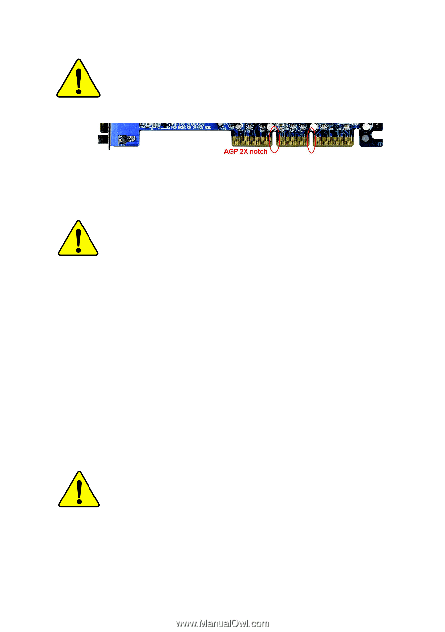
When you installing AGP card, please make sure the following
notice is fully understood and practiced.
If your AGP card has
"AGP 4X/8X (1.5V) notch"(show below), please make sure your
AGP card is AGP 4X/8X (1.5V).
Caution: AGP 2X card is not supported by Intel
®
845(GE/PE) / 845(E/
G) / 850(E) / E7205 / 865(G/PE/P) / 875P. You might experience system
unable to boot up normally. Please insert an AGP 4X/8X card.
Example 1: Diamond Vipper V770 golden finger is compatible with 2X/4X
mode AGP slot. It can be switched between AGP 2X(3.3V) or 4X(1.5V)
mode by adjusting the jumper. The factory default for this card is
2X(3.3V). The GA-8IPE775 Series (or any AGP 4X/8X only)
motherboards might not function properly, if you install this card without
switching the jumper to 4X(1.5V) mode in it.
Example 2: Some ATi Rage 128 Pro graphics cards made by "Power Color",
the graphics card manufacturer & some SiS 305 cards, their golden finger
is compatible with 2X(3.3V)/4X(1.5V) mode AGP slot, but they support 2X
(3.3V) only. The GA-8IPE775 Series (or any AGP 4X/8X only)
motherboards might not function properly, If you install this card in it.
Note : Although Gigabyte's AG32S(G) graphics card is based on ATi Rage
128 Pro chip, the design of AG32S(G) is compliance with AGP 4X(1.5V)
specification. Therefore, AG32S(G) will work fine with Intel
®
845(GE/PE) /
845(E/G) / 850(E) / E7205 / 865(G/PE/P) / 875P based motherboards.
Before you install PCI cards, please remove the Dual BIOS label from
PCI slots if there is one.
AGP 4X/8X notch