Gigabyte GA-8N-SLI Pro Manual
Gigabyte GA-8N-SLI Pro Manual
 |
View all Gigabyte GA-8N-SLI Pro manuals
Add to My Manuals
Save this manual to your list of manuals |
Gigabyte GA-8N-SLI Pro manual content summary:
- Gigabyte GA-8N-SLI Pro | Manual - Page 1
GA-8N-SLI Royal/ GA-8N-SLI Pro/ GA-8N-SLI Intel® Pentium® Processor Extreme Edition Intel® Pentium® D / Pentium® 4 LGA775 Processor Motherboard User's Manual Rev. 1004 12ME-8NSLIRO-1004 - Gigabyte GA-8N-SLI Pro | Manual - Page 2
Motherboard GA-8N-SLI Royal May 6, 2005 Motherboard GA-8N-SLI Royal May 6, 2005 - Gigabyte GA-8N-SLI Pro | Manual - Page 3
Motherboard GA-8N-SLI Pro June 2, 2005 Motherboard GA-8N-SLI Pro June 2, 2005 - Gigabyte GA-8N-SLI Pro | Manual - Page 4
Motherboard GA-8N-SLI Oct. 26, 2005 Motherboard GA-8N-SLI Oct. 26, 2005 - Gigabyte GA-8N-SLI Pro | Manual - Page 5
product information and specifications, please carefully read the "Product User Manual". „ For detailed information related to Gigabyte's unique features, please go to "Technology Guide" section on Gigabyte's website to read or download the information you need. For more product details, please - Gigabyte GA-8N-SLI Pro | Manual - Page 6
Table of Contents GA-8N-SLI Royal / GA-8N-SLI Pro / GA-8N-SLI Motherboard Layout 8 Block Diagram ...9 Chapter 1 Hardware Installation 11 1-1 Considerations Prior to Installation 11 1-2 Feature Summary 12 1-3 Installation of the CPU and Heatsink 14 1-3-1 Installation of the CPU 14 1-3-2 - Gigabyte GA-8N-SLI Pro | Manual - Page 7
57 3-1 Install Chipset Drivers 57 3-2 SoftwareApplication 58 3-3 Software Information 58 3-4 Hardware Information 59 3-5 Contact Us ...59 Chapter 4 Appendix 61 4-1 Unique Software Utilities 61 4-1-1 EasyTune 5 Introduction 62 4-1-2 Xpress Recovery2 Introduction 63 4-1-3 Flash BIOS Method - Gigabyte GA-8N-SLI Pro | Manual - Page 8
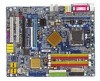
LPT GA-8N-SLI Royal (Pro)/GA-8N-SLI DDRII1 DDRII2 DDRII3 DDRII4 LAN1 LAN2 USB FDD USB Marvell Phy (LAN2) AUDIO1 AUDIO2 CPU_FAN ATX_12V nVIDIA® nForce 4 SLI Intel Edition F_AUDIO Marvell 8053 (LAN1) PCIE_12V Main BIOS Backup PCIE_2 BIOS NB_FAN PCIE_1 PCIE_16_1 SLI Switch Module Socket - Gigabyte GA-8N-SLI Pro | Manual - Page 9
) Marvell 8053 2 PCI Express x 1 RJ45 LAN 1 PCI Bus PDC20779 TSB82AA2 TSB81BA3 LAN 2 RJ45 Marvell PHY nVIDIA® MCP-04 CODEC 33MHz 25MHz 48MHz Dual BIOS ROMCLK33MHz 4 SATA 3Gb/s ATA33/66/100/133 SPDIF In SPDIF Out PCICLK (33MHz) Only for GA-8N-SLI Royal. Only for GA-8N-SLI Pro. - 9 - - Gigabyte GA-8N-SLI Pro | Manual - Page 10
- 10 - - Gigabyte GA-8N-SLI Pro | Manual - Page 11
off the computer and unplug its power cord. 2. When handling the motherboard, avoid touching any metal leads or connectors. 3. It is best to wear an electrostatic discharge (ESD) cuff when handling electronic components (CPU, RAM). 4. Prior to installing the electronic components, please have these - Gigabyte GA-8N-SLI Pro | Manual - Page 12
English 1-2 Feature Summary Motherboard Š CPU Š Š Š Chipset Š Š Š Memory Š Š Š Slots Š Š Š IDE Connections Š Š FDD Connections Š Onboard SATA 3Gb/s Š Peripherals Š Š Š Š Š Š Š Onboard LAN Š Š Š GA-8N-SLI Royal or GA-8N-SLI Pro or GA-8N-SLI Supports LGA775 Intel® - Gigabyte GA-8N-SLI Pro | Manual - Page 13
DPS Supports @BIOS Supports EasyTune 5 (Note 2) Over Voltage via BIOS (FSB/DIMM/PCIE/SATA II/CPU) Over Clock via BIOS (CPU/DIMM/PCIE) ATX form factor; 30.5cm x 24.4cm (Note 2) EasyTune 5 functions may vary depending on different motherboards. Only for GA-8N-SLI Royal. Only for GA-8N-SLI Pro. - 13 - Gigabyte GA-8N-SLI Pro | Manual - Page 14
- Chipset: A NVIDIA® Chipset that supports HT Technology - BIOS: A BIOS that supports HT Technology and has it enabled - OS: An operation system that has optimizations for HT Technology 1-3-1 Installation of the CPU Metal Lever Fig. 1 Gently lift the metal lever located on the CPU socket to - Gigabyte GA-8N-SLI Pro | Manual - Page 15
the CPU and make sure the push pins aim to the pin hole on the motherboard.Pressing down the push pins diagonally. Fig. 4 Please make sure the Male and Female push pin are joined closely. (for detailed installation instructions, please refer to the heatsink installation section of the user manual - Gigabyte GA-8N-SLI Pro | Manual - Page 16
whereby BIOS will automatically detect memory capacity and specifications. Memory modules are designed so that they can be inserted only in one direction. The memory capacity used can differ with each slot. Only for GA-8N-SLI Royal. Only for GA-8N-SLI Pro. P4 nForce4 SLI Series Motherboard - 16 - Gigabyte GA-8N-SLI Pro | Manual - Page 17
.2 Close the plastic clip at both edges of the DIMM sockets to lock the DIMM module. Reverse the installation steps when you wish to remove the DIMM module. Dual Channel DDR II GA-8N-SLI Royal/GA-8N-SLI Pro/GA-8N-SLI supports the Dual Channel Technology. After operating the Dual Channel Technology - Gigabyte GA-8N-SLI Pro | Manual - Page 18
Read the related expansion card's instruction document before install the expansion necessary, setup BIOS utility of expansion card from BIOS. 8. Install related driver from the by the small white-drawable bar. P4 nForce4 SLI Series Motherboard The PCIE_12V power connector supplies extra power to - Gigabyte GA-8N-SLI Pro | Manual - Page 19
Plus DPS can only fit in one direction. 2. Insert the U-Plus DPS vertically into the socket and then push it down. 3. Fix the U-Plus DPS on the motherbard with the clip. 4. Reverse the installation steps if you want to remove the U-Plus DPS. Only for GA-8N-SLI Royal. - 19 - Hardware Installation - Gigabyte GA-8N-SLI Pro | Manual - Page 20
Edition chipset. Together, the NVIDIA SLI technologies work seamlessly to allow two graphics cards to operate in parallel and share the work and deliver heart-pounding PC performance. This section introduces steps to configure an SLI system on the GA-8N-SLI Royal/GA-8N-SLI Pro/GA-8N-SLI motherboard - Gigabyte GA-8N-SLI Pro | Manual - Page 21
Supported Operating Systems: Only Windows XP operating system is currently supported by the NVIDIA SLI technology. Enabling SLI Mode-- Set the SLI on the two ends of the module until it is locked in place by the socket clips. (You should hear a "click" when the module is attached.) Connecting - Gigabyte GA-8N-SLI Pro | Manual - Page 22
BIOS Driver Setting: Step 1: After installing graphics card driver SLI multi-GPU from the side menu and then select the Enable SLI multi-GPU checkbox in the SLI multi-GPU dialog box. System will restart after you click Apply. Then the SLI configuration is completed. P4 nForce4 SLI Series Motherboard - Gigabyte GA-8N-SLI Pro | Manual - Page 23
USB interface. Also make sureyour OS supports USB controller. If your OS does not support USB controller, please contact OS vendor for possible patch or driver upgrade. For more information please contact surround speakers to this connector. Only for GA-8N-SLI Royal. - 23 - Hardware Installation - Gigabyte GA-8N-SLI Pro | Manual - Page 24
13) F_AUDIO 14) CD_IN 15) SPDIF_IN 16) F_USB1 / F_USB2/F_USB3 17) F1_1394/F2_1394 18) CLR_CMOS 19) CI 20) PCIE_12V 21) BATTERY 22) RF_ID Only for GA-8N-SLI Royal. Only for GA-8N-SLI Pro. P4 nForce4 SLI Series Motherboard - 24 - - Gigabyte GA-8N-SLI Pro | Manual - Page 25
all components and devices are properly installed. Align the power connector with its proper location on the motherboard and connect tightly. The ATX_12V power connector mainly supplies power to the CPU. If the ATX_12V power connector is not connected, the system will not start. Caution! Please use - Gigabyte GA-8N-SLI Pro | Manual - Page 26
system overheating and failure. Caution! Please remember to connect the power to the CPU fan to prevent CPU overheating and failure. 1 CPU_FAN 1 SYS_FAN 1 PWR_FAN Pin No. 1 2 1 1 +12V 2 GND Only for GA-8N-SLI Royal. Only for GA-8N-SLI Pro. P4 nForce4 SLI Series Motherboard - 26 - - Gigabyte GA-8N-SLI Pro | Manual - Page 27
the cable connects to the FDD drive. The types of FDD drives supported are: 360KB, 720KB, 1.2MB, 1.44MB and 2.88MB. Please connect instructions located on the IDE device). To ensure that an IDE CD-ROM drive can work properly, please attach it to the IDE 1/IDE 2 connector. 40 39 Only for GA-8N-SLI - Gigabyte GA-8N-SLI Pro | Manual - Page 28
3Gb/s can provide up to 300MB/s transfer rate. Please refer to the BIOS setting for the SATA 3Gb/s and install the proper driver in order to work properly. Pin No. Definition 1 GND 7 1 2 Definition 1 MPD+ 2 MPD- 3 MPD- Only for GA-8N-SLI Royal. P4 nForce4 SLI Series Motherboard - 28 - - Gigabyte GA-8N-SLI Pro | Manual - Page 29
English 12 F_PANEL (Front Panel Jumper) Please connect the power LED, PC speaker, reset switch and power switch etc of your chassis front panel to the F_PANEL connector according to the pin assignment below. Message LED/ Power/ Sleep LED Speaker Connector Power Switch MSG+ MSG- PW+ PWSPEAK+ - Gigabyte GA-8N-SLI Pro | Manual - Page 30
the pin assigments on the MB header. To find out if the chassis you are buying support front audio connector, please contact your dealer.Please note, you can have the alternative of using connector. Pin No. Definition 1 1 CD-L 2 GND 3 GND 4 CD-R P4 nForce4 SLI Series Motherboard - 30 - - Gigabyte GA-8N-SLI Pro | Manual - Page 31
English 15) SPDIF_IN (SPDIF In) Use SPDIF IN feature only when your device has digital output function. Be careful with the polarity of the SPDIF_IN connector. Check the pin assignment carefully while you connect the SPDIF cable, incorrect connection between the cable and connector will make the - Gigabyte GA-8N-SLI Pro | Manual - Page 32
clear CMOS, temporarily short 1-2 pin. Default doesn't include the jumper to prevent from improper use of this header. 1 Open: Normal 1 Short: Clear CMOS Only for GA-8N-SLI Royal. Only for GA-8N-SLI Pro. P4 nForce4 SLI Series Motherboard - 32 - - Gigabyte GA-8N-SLI Pro | Manual - Page 33
, Case Open) This 2-pin connector allows your system to detect if the chassis cover is removed. You can check the "Case Opened" status in BIOS Setup. Pin No. Definition 1 1 Signal 2 GND 20) PCIE_12V (Power Connector) The PCIE_12V power connector supplies extra power to the PCI Exress 16 slots - Gigabyte GA-8N-SLI Pro | Manual - Page 34
by the manufacturer. Dispose of used batteries according to the manufacturer's instructions. If you want to erase CMOS... 1. Turn OFF the computer GIGABYTE external device. Pin No. Definition 1 Power 1 2 RFID_RI- 3 RF_TXD 4 RF_RXD 5 NC 6 GND P4 nForce4 SLI Series Motherboard - Gigabyte GA-8N-SLI Pro | Manual - Page 35
. Status Page Setup Menu / Option Page Setup Menu Press to pop up a small help window that describes the appropriate keys to use and the possible selections for the highlighted item. To exit the Help Window press . Only for GA-8N-SLI Royal. Only for GA-8N-SLI Pro. - 35 - BIOS Setup - Gigabyte GA-8N-SLI Pro | Manual - Page 36
Password Set User Password Save & Exit Setup Exit Without Saving ESC: Quit F8: Dual BIOS12/Q-Flash F3: Change CPU clock and frequency ratio. „ Select Language This setup page is to select multilanguages. Only for GA-8N-SLI Royal. Only for GA-8N-SLI Pro. P4 nForce4 SLI Series Motherboard - Gigabyte GA-8N-SLI Pro | Manual - Page 37
. „ Set Supervisor Password Change, set, or disable password. It allows you to limit access to the system and Setup, or just to Setup. „ Set User Password Change, set, or disable password. It allows you to limit access to the system. „ Save & Exit Setup Save CMOS value settings to CMOS and - Gigabyte GA-8N-SLI Pro | Manual - Page 38
1 Slave Drive A Drive B Floppy 3 Mode Support [None] [None] [None] [None] [1. Exit F1: General Help F3: Language12 F5: Previous Values Sat, determined by the BIOS and is display only Manual User can manually GA-8N-SLI Royal. Only for GA-8N-SLI Pro. P4 nForce4 SLI Series Motherboard - 38 - - Gigabyte GA-8N-SLI Pro | Manual - Page 39
inch double-sided drive; 2.88M byte capacity. Floppy 3 Mode Support (for Japan Area) Disabled Normal Floppy Drive. (Default value) motherboard. Extended Memory The BIOS determines how much extended memory is present during the POST. This is the amount of memory located above 1 MB in the CPU - Gigabyte GA-8N-SLI Pro | Manual - Page 40
BIOS Features ` Hard Disk Boot Priority First Boot Device Second Boot Device Third Boot Device ROM Boot Priority1 Boot Up Floppy Seek Password Check CPU you install a processor that supports this function. Only for GA-8N-SLI Royal. Only for GA-8N-SLI Pro. P4 nForce4 SLI Series Motherboard - 40 - - Gigabyte GA-8N-SLI Pro | Manual - Page 41
BIOS can not tell from 720K, 1.2M or 1.44M drive type as they are all 80 tracks. BIOS system with multiprocessors mode supported. (Default value) Disabled Disable CPU Hyper-Threading. Limit PCI card and a PCI Express VGA card on the motherboard. PCI Slot Set Init Display First to PCI VGA card. - Gigabyte GA-8N-SLI Pro | Manual - Page 42
Disable this function. (Default value) IDE Secndry Master RAID Enabled Disabled Enable 2nd master channel IDE RAID function. Disable this function. (Default value) Only for GA-8N-SLI Royal. Only for GA-8N-SLI Pro. P4 nForce4 SLI Series Motherboard - 42 - - Gigabyte GA-8N-SLI Pro | Manual - Page 43
2 (Onboard nVIDIA chipset) Enabled Disabled Enable Serial-ATAII 2 support. (Default Value) Disable Serial-ATAII 2 support. On-Chip USB V1.1+V2.0 Enable USB 1.1 and USB 2.0 controllers. (Default Value) V1.1 Disabled Enable only USB 1.1 controller Disable onchip USB support. - 43 - BIOS Setup - Gigabyte GA-8N-SLI Pro | Manual - Page 44
Disable USB mouse support. (Default value) AC97 Audio Auto Autodetect onboard AC'97 audio function. (Default value) Disabled Disable this function. Onboard LAN2 Function (Marvell 88E1111/88E1115) (For the GA-8N-SLI Pro/GA-8N-SLI motherboard, the item is Onboard LAN Function) Auto Autodetect - Gigabyte GA-8N-SLI Pro | Manual - Page 45
/PD: Value F10: Save ESC: Exit F1: General Help F3: Language12 F5: Previous Values F6: Fail-Safe Defaults F7: value) Set ACPI suspend type to S3/STR(Suspend To RAM). Soft-Off by Power button Instant-Off Press power button then for GA-8N-SLI Royal. Only for GA-8N-SLI Pro. - 45 - BIOS Setup - Gigabyte GA-8N-SLI Pro | Manual - Page 46
system will be in "Off" state. (Default value) Full-On When AC-power back to the system, the system always in "On" state. P4 nForce4 SLI Series Motherboard - 46 - - Gigabyte GA-8N-SLI Pro | Manual - Page 47
KLJI: Move Enter: Select +/-/PU/PD: Value F10: Save ESC: Exit F1: General Help F3: Language12 F5: Previous Values F6: Fail-Safe Defaults F7: Optimized Defaults PCI 1 IRQ Assignment Auto 10,11,12,14,15 to PCI 2. Only for GA-8N-SLI Royal. Only for GA-8N-SLI Pro. - 47 - BIOS Setup - Gigabyte GA-8N-SLI Pro | Manual - Page 48
F1: General Help F3: Language12 F5: CPU/POWER /SYSTEM FAN Fail Warning Disabled Enabled Disable CPU/Power /System fan fail warning function. (Default value) Enable CPU/Power /System fan fail warning function. Only for GA-8N-SLI Royal. Only for GA-8N-SLI Pro. P4 nForce4 SLI Series Motherboard - Gigabyte GA-8N-SLI Pro | Manual - Page 49
at different speed depending on CPU temperature. Users can adjust the fan speed with Easy Tune based on their requirements. (Default value) CPU Smart FAN Mode This option is available only when CPU Smart FAN Control is enabled. Auto BIOS autodetects the type of CPU fan you installed and sets - Gigabyte GA-8N-SLI Pro | Manual - Page 50
Help F3: Language12 CPU frequency(17%,19%) by CPU loading. Warning: Stability is highly dependent on system components. (Note) This item will show up when you install a processor that supports this function. Only for GA-8N-SLI Royal. Only for GA-8N-SLI Pro. P4 nForce4 SLI Series Motherboard - Gigabyte GA-8N-SLI Pro | Manual - Page 51
be overclocked proportionally. Enter FSB and memory speed manually. New FSB Speed (QDR) This item FSB speed. Current FSB Speed (QDR) Displays the current CPU FSB speed. Target FSB Speed (QDR) This item depends LDT frequency. SLI Broadcast Aperture Auto Set SLI Broadcast Aperture BIOS Setup - Gigabyte GA-8N-SLI Pro | Manual - Page 52
CPU Voltage Control Supports adjustable CPU Vcore from 0.8375V to 1.6000V. (Default value: Normal) Warning: CPU may be damaged or CPU life-cycle may be reduced when CPU is over-voltage. Normal CPU Vcore Display your CPU Robust Graphics Booster to Turbo. P4 nForce4 SLI Series Motherboard - 52 - - Gigabyte GA-8N-SLI Pro | Manual - Page 53
Esc: Quit F8: Dual BIOS12/Q-Flash F3: Change Language12 F10: Save & Exit Setup Load Optimized Defaults Selecting this field loads the factory defaults for BIOS and Chipset Features which the system automatically detects. Only for GA-8N-SLI Royal. Only for GA-8N-SLI Pro. - 53 - BIOS Setup - Gigabyte GA-8N-SLI Pro | Manual - Page 54
Password Set User Password Save & Exit Setup Exit Without Saving Esc: Quit F8: Dual BIOS12/Q-Flash F3: Change Language12 in Advance BIOS Features Menu, you will be prompted only when you try to enter Setup. Only for GA-8N-SLI Royal. Only for GA-8N-SLI Pro. P4 nForce4 SLI Series Motherboard - 54 - Gigabyte GA-8N-SLI Pro | Manual - Page 55
` PnP/PCI Configurations Set User Password ` PC Health Status F3: Change Language12 F10: Save & Exit Setup Abandon all Data Type "Y" will quit the Setup Utility without saving to RTC CMOS. Type "N" will return to Setup Utility. Only for GA-8N-SLI Royal. Only for GA-8N-SLI Pro. - 55 - BIOS - Gigabyte GA-8N-SLI Pro | Manual - Page 56
English P4 nForce4 SLI Series Motherboard - 56 - - Gigabyte GA-8N-SLI Pro | Manual - Page 57
, please use Windows Service Pack. After install Windows Service Pack, it will show a question mark "?" in "Universal Serial Bus controller" under "Device Manager". Please remove the question mark and restart the system (System will auto-detect the right USB2.0 driver). Only for GA-8N-SLI Royal - Gigabyte GA-8N-SLI Pro | Manual - Page 58
Application This page displays all the tools that Gigabyte developed and some free software, you can choose anyone you want and press "install" to install them. 3-3 Software Information This page lists the contents of software and drivers in this CD-title. P4 nForce4 SLI Series Motherboard - 58 - - Gigabyte GA-8N-SLI Pro | Manual - Page 59
English 3-4 Hardware Information This page lists all device you have for this motherboard. 3-5 Contact Us Please see the last page for details. - 59 - Drivers Installation - Gigabyte GA-8N-SLI Pro | Manual - Page 60
English P4 nForce4 SLI Series Motherboard - 60 - - Gigabyte GA-8N-SLI Pro | Manual - Page 61
) Motherboard Intelligent Tweaker (M.I.T.) allows user to access and change BIOS feature settings with relative speed and ease. Through GIGABYTE M.I.T. feature the user is no longer required to switch into different modes within BIOS setup in order to change system settings such as the CPU system - Gigabyte GA-8N-SLI Pro | Manual - Page 62
and Advance Mode Display panel of CPU frequency Shows the current functions status Log on to GIGABYTE website Display EasyTuneTM 5 Help file Quit or Minimize EasyTuneTM 5 software (Note) EasyTune 5 functions may vary depending on different motherboards. P4 nForce4 SLI Series Motherboard - 62 - - Gigabyte GA-8N-SLI Pro | Manual - Page 63
quick backup and restoration of hard disk data. Supporting Microsoft operating systems including Windows XP/2000/NT/98/Me and DOS, and CD/DVD: Award Modular BIOS v6.00PG, An Energy Star Ally Copyright (C) 1984-2005, Award Software, Inc. GA-8N-SLI Royal F5a . . . . :BIOS Setup/Q-Flash, : - Gigabyte GA-8N-SLI Pro | Manual - Page 64
supports only PATA hard disks and not SATA hard disks on the following motherboards (As this is a BIOS-related issue, it can be solved by BIOS update) GA-K8U GA-K8NXP-9 GA-8N-SLI Royal GA-K8U-9 GA-K8N Ultra-9 GA-8N-SLI Pro GA-K8NXP-SLI GA-K8NF-9 (PCB Ver. 1.0) GA-8N-SLI GA-K8N Ultra-SLI - Gigabyte GA-8N-SLI Pro | Manual - Page 65
Settings Save Settings to CMOS Q-Flash Utility Update Main BIOS from Floppy Update Backup BIOS from Floppy Save Main BIOS to Floppy Save Backup BIOS to Floppy PgDn/PgUp: Modify : Move ESC: Reset 512K 512K F10: Power Off Only for GA-8N-SLI Royal. Only for GA-8N-SLI Pro. - 65 - Appendix - Gigabyte GA-8N-SLI Pro | Manual - Page 66
Backup BIOS works normally and could automatically recover the Main BIOS. (This auto recovery utility is set by system automatically and can't be changed by user.) Load Default Settings Load dual BIOS default value. Save Settings to CMOS Save revised setting. P4 nForce4 SLI Series Motherboard - 66 - Gigabyte GA-8N-SLI Pro | Manual - Page 67
avoid any claims from end-users. Before You Begin: Before you start updating BIOS with the Q-FlashTM utility, please follow the steps below first. 1. Download the latest BIOS for your motherboard from Gigabyte's website. 2. Extract the BIOS file downloaded and save the BIOS file (the one with model - Gigabyte GA-8N-SLI Pro | Manual - Page 68
BIOS/Q-Flash Select Language Load Fail-Safe Defaults Load Optimized Defaults Set Supervisor Password Set User Password Save & Exit Setup Exit Without Saving F3 /Dual BIOS utility. Pressing the buttons mentioned on your keyboards to perform these actions. P4 nForce4 SLI Series Motherboard - 68 - - Gigabyte GA-8N-SLI Pro | Manual - Page 69
flash and press Enter. In this example, we only download one BIOS file to the floppy disk so only one BIOS file, 8KNXPU.Fba, is listed. Please confirm again you have the correct BIOS file for your motherboard. Dual BIOS Utility Boot From Main Bios Main ROM Type/Size SST 49LF004A Backup ROM Type - Gigabyte GA-8N-SLI Pro | Manual - Page 70
Primary Master : FUJITSU MPE3170AT ED-03-08 Primary Slave : None Secondary Master : CREATIVEDVD-RM DVD1242E BC101 Secondary Slave : None Press DEL to enter SETUP / Dual BIOS / Q-Flash / F9 For Xpress Recovery 09/23/2003-i875P-6A79BG03C-00 P4 nForce4 SLI Series Motherboard - 70 - - Gigabyte GA-8N-SLI Pro | Manual - Page 71
F8: Dual BIOS/Q-Flash F3: Change Language F10: Save & Exit Setup Time, Date, Hard Disk Type... Press Y on your keyboard to save and exit. Part Two: Updating BIOS with Q-FlashTM Utility on Single-BIOS Motherboards. This part guides users of single-BIOS motherboards how to update BIOS using the - Gigabyte GA-8N-SLI Pro | Manual - Page 72
file you want to flash and press Enter. In this example, we only download one BIOS file to the floppy disk so only one BIOS file, 8GE800.F4, is listed. Please confirm again you have the correct BIOS file for your motherboard. Q-Flash Utility V1.30 Flash Type/Size SST 49LF003A 256K 8GE800.F4Keep - Gigabyte GA-8N-SLI Pro | Manual - Page 73
:Power Off Do not trun off power or reset your system at this stage!! 4. Press any keys to return to the Q-Flash menu when the BIOS updating procedure is completed. Q-Flash Utility V1.30 Flash Type/Size SST 49LF003A 256K Enter : Run Keep DMI Data Enable !! CopUypBdaItOe SBIcOomS pfrloemtedFl - Gigabyte GA-8N-SLI Pro | Manual - Page 74
the new @BIOS utility. @BIOS allows users to update their BIOS under Windows. Just select the desired @BIOS server to download the latest version of BIOS. Fig 1. Installing the @BIOS utility Fig 2. Installation complete and run @BIOS Click Start/ Programs/ GIGABYTE/@BIOS Select @BIOS item than - Gigabyte GA-8N-SLI Pro | Manual - Page 75
In method II, be sure that motherboard's model name in BIOS unzip file are the same as your motherboard's. Otherwise, your system won't boot. III. In method I, if the BIOS file you need cannot be found in @BIOSTM server, please go onto Gigabyte's web site for downloading and updating it according to - Gigabyte GA-8N-SLI Pro | Manual - Page 76
English 4-1-4 Serial ATA BIOS Setting Utility Introduction RAID Levels RAID and implementation costs. The RAID levels which the nVIDIA® MCP-04 chipset supports are RAID 0, RAID 1, RAID 0+RAID 1, JBOD and RAID 5; the any data loss. Only for GA-8N-SLI Royal. P4 nForce4 SLI Series Motherboard - 76 - - Gigabyte GA-8N-SLI Pro | Manual - Page 77
Support\ Motherboard\ Technology Guide section" on our website at http:\\www.gigabyte.com.tw to read or download the information you need.) Configuring the Nvidia RAID BIOS The NVRAID BIOS seconds to press F10 before the window disappears. MediaShield IDE ROM BIOS 5.16 Copyright (C) 2005 NVIDIA Corp - Gigabyte GA-8N-SLI Pro | Manual - Page 78
"Define a New Array" Window If necessary, press the 128 KB. Assigning the Disks The disks that you enabled from the RAID Config BIOS setup page appear in the Free Disks block. These are the drives that are F7] Finish [TAB] Navigate [ ] Select [ENTER] Popup P4 nForce4 SLI Series Motherboard - 78 - - Gigabyte GA-8N-SLI Pro | Manual - Page 79
English Completing the RAID BIOS Setup After assigning your RAID array disks, press F7. The Clear disk You must choose Yes if the drives were previously used as RAID drives. The Array List window appears, where you can review the RAID arrays that you have set up. You can select a disk array as boot - Gigabyte GA-8N-SLI Pro | Manual - Page 80
back to the previous screen and then press Ctrl + X to exit the RAID setup. Now that the RAID setup has been configured from the RAID BIOS, the next step is to configure and load drivers under Windows. P4 nForce4 SLI Series Motherboard - 80 - - Gigabyte GA-8N-SLI Pro | Manual - Page 81
manually. To view the disk drives assigned to arrays, press to enter the View Drive Assignments window. To delete an array, press to enter the Delete Array window. To recover from an error in a mirrored (RAID 1) disk array, press to enter the Rebuild Array window. Only for GA-8N-SLI - Gigabyte GA-8N-SLI Pro | Manual - Page 82
array automatically, press to enter the Auto Setup window. The Auto Setup selection from the Main Menu can intuitively go to the Define Array window. Security: Under the Security setting (RAID 1), FastTrak assigns two drives to a single Mirrored array. P4 nForce4 SLI Series Motherboard - 82 - - Gigabyte GA-8N-SLI Pro | Manual - Page 83
Manually To create a new array manually, press to enter the Define Array window. The Define Array selection from the Main Menu allows users to begin the process of manually process will stop when the FastTrak BIOS appears and wait for your Stripe Block: 64KB Gigabyte Rounding: OFF Channel - Gigabyte GA-8N-SLI Pro | Manual - Page 84
manually select the stripe block size. Press the Space bar to scroll through choices from 32 to 128KB. The default is 64KB. Gigabyte Rounding: The Gigabyte Rounding feature is designed for Mirrored (RAID 1) arrays in which a drive has failed and the user window BIOS SLI Series Motherboard - 84 - - Gigabyte GA-8N-SLI Pro | Manual - Page 85
Definition Menu] Logical Disk No RAID Mode Total Drv Capacity (MB) Status Logical Disk 1 Stripe 2 240068 Functional Stripe Block: 64KB Gigabyte Rounding: OFF Channel:ID 1:SATA 2:SATA [ Drives Assignments] ] Drive Model ST3120026AS ST3120026AS Capacity (MB) 120034 120034 Are you sure - Gigabyte GA-8N-SLI Pro | Manual - Page 86
recognized during the Windows setup process. First of all, copy the driver for the SATA controller from the motherboard driver CD-ROM to a floppy disk. See the instructions below about how to copy the driver in MS-DOS mode(Note1). Prepare a startup disk that has CD-ROM support and a blank formatted - Gigabyte GA-8N-SLI Pro | Manual - Page 87
Channel Audio Function Introduction This motherboard provide 6 audio connector. to install the function. (Following pictures are in Windows XP) Stereo Speakers Connection and Settings: We Out STEP 2 : Following installation of the audio driver, you find a Sound Effect icon on the lower right hand - Gigabyte GA-8N-SLI Pro | Manual - Page 88
", the rear channels to "Rear Speaker Out". STEP 2 : Following installation of the audio driver, you find a Sound Effect icon on the lower right hand taskbar. Click the icon to to complete 4 channel audio configuration. P4 nForce4 SLI Series Motherboard - 88 - Front Speaker Out Rear Speaker Out - Gigabyte GA-8N-SLI Pro | Manual - Page 89
the rear channels to "Rear Speaker Out", and the Center/Subwoofer channels to "Center/Subwoofer Speaker Out". STEP 2 : Following installation of the audio driver, you find a Sound Effect icon on the lower right hand taskbar. Click the icon to select the function. STEP 3: Click "Speaker Configuration - Gigabyte GA-8N-SLI Pro | Manual - Page 90
side channels to "Side Speaker Out". STEP 2 : Following installation of the audio driver, you find a Sound Effect icon on the lower right hand taskbar. Click the icon : At the sound effect menu, users can adjust sound option settings as desired. P4 nForce4 SLI Series Motherboard - 90 - - Gigabyte GA-8N-SLI Pro | Manual - Page 91
Troubleshooting Below is a collection of general asked questions. To check general asked questions based on a specific motherboard model, please log on to www.gigabyte.com.tw Question 1: I cannot see some options that were included in previous BIOS after updating BIOS steps in the manual. If your - Gigabyte GA-8N-SLI Pro | Manual - Page 92
English P4 nForce4 SLI Series Motherboard - 92 - - Gigabyte GA-8N-SLI Pro | Manual - Page 93
- 93 - Appendix English - Gigabyte GA-8N-SLI Pro | Manual - Page 94
English P4 nForce4 SLI Series Motherboard - 94 - - Gigabyte GA-8N-SLI Pro | Manual - Page 95
.giga-byte.com U.S.A. G.B.T. INC. TEL: +1-626-854-9338 FAX: +1-626-854-9339 Tech. Support : http://tw.giga-byte.com/TechSupport/ServiceCenter.htm Non-Tech. Support(Sales/Marketing) : http://ggts.gigabyte.com.tw/nontech.asp WEB address : http://www.giga-byte.com Germany G.B.T. TECHNOLOGY TRADING GMBH - Gigabyte GA-8N-SLI Pro | Manual - Page 96
Representative Office Of GIGA-BYTE Technology Co., Ltd. in Romania Tech. Support : http://tw.giga-byte.com/TechSupport/ServiceCenter.htm Non-Tech. Support(Sales/Marketing) : http://ggts.gigabyte.com.tw/nontech.asp WEB address: http://www.gigabyte.com.ro P4 nForce4 SLI Series Motherboard - 96 -
-
 1
1 -
 2
2 -
 3
3 -
 4
4 -
 5
5 -
 6
6 -
 7
7 -
8
-
9
-
10
-
11
-
12
-
13
-
14
-
15
-
16
-
17
-
18
-
19
-
20
-
21
-
22
-
23
-
24
-
25
-
26
-
27
-
28
-
29
-
30
-
31
-
32
-
33
-
34
-
35
-
36
-
37
-
38
-
39
-
40
-
41
-
42
-
43
-
44
-
45
-
46
-
47
-
48
-
49
-
50
-
51
-
52
-
53
-
54
-
55
-
56
-
57
-
58
-
59
-
60
-
61
-
62
-
63
-
64
-
65
-
66
-
67
-
68
-
69
-
70
-
71
-
72
-
73
-
74
-
75
-
76
-
77
-
78
-
79
-
80
-
81
-
82
-
83
-
84
-
85
-
86
-
87
-
88
-
89
-
90
-
91
-
92
-
93
-
94
-
95
-
96
 |
 |

GA-8N-SLI Royal/
GA-8N-SLI Pro/
GA-8N-SLI
Intel
®
Pentium
®
Processor Extreme Edition
Intel
®
Pentium
®
D / Pentium
®
4 LGA775 Processor Motherboard
User's Manual
Rev. 1004
12ME-8NSLIRO-1004