Gigabyte GA-8S648FXP-RZ User Manual
Gigabyte GA-8S648FXP-RZ Manual
 |
View all Gigabyte GA-8S648FXP-RZ manuals
Add to My Manuals
Save this manual to your list of manuals |
Gigabyte GA-8S648FXP-RZ manual content summary:
- Gigabyte GA-8S648FXP-RZ | User Manual - Page 1
finger is compatible with 2X(3.3V)/4X(1.5V) mode AGP slot, but they support 2X(3.3V) only. The GA-8SG800/GA-8S648FX (or any AGP 4X only) motherboards might not function properly, If you install this card in it. Note : Although Gigabyte's AG32S(G) graphics card is based on ATi Rage 128 Pro chip, the - Gigabyte GA-8S648FXP-RZ | User Manual - Page 2
. M Third-party brands and names are the property of their respective owners. M Please do not remove any labels on motherboard, this may void the warranty of this motherboard. M Due to rapid change in technology, some of the specifications might be out of date before publication of this booklet - Gigabyte GA-8S648FXP-RZ | User Manual - Page 3
41, 1F, 20537 Hamburg, Germany declare that the product ( description of the apparatus, system, installation to which it refers) Mother Board GA-8SG800/GA-8S648FX is in conformity with (reference to the specification under which conformity is declared) in accordance with 89/336 EEC-EMC Directive - Gigabyte GA-8S648FXP-RZ | User Manual - Page 4
City of Industry, CA 91748 Phone/Fax No: (818) 854-9338/ (818) 854-9339 hereby declares that the product Product Name: Motherboard Model Number: GA-8SG800/GA-8S648FX Conforms to the following specifications: FCC Part 15, Subpart B, Section 15.107(a) and Section 15.109 (a),Class B Digital Device - Gigabyte GA-8S648FXP-RZ | User Manual - Page 5
GA-8SG800/GA-8S648FX P4 Titan Series Motherboard USER'S MANUAL Pentium® 4 Processor Motherboard Rev. 1103 12ME-8SG800-1103 - Gigabyte GA-8S648FXP-RZ | User Manual - Page 6
4 WARNING 4 Chapter 1 Introduction 5 Features Summary 5 GA-8SG800/GA-8S648FX Motherboard Layout 7 Chapter 2 Hardware Installation Process 8 Step 1: 15 Chapter 3 BIOS Setup 23 The Main Menu (For example: BIOS Ver. : F2 24 Standard CMOS Features 26 Advanced BIOS Features 29 Integrated - Gigabyte GA-8S648FXP-RZ | User Manual - Page 7
Password 45 Save & Exit Setup 46 Exit Without Saving 47 Chapter 4 Technical Reference 49 Block Diagram 49 @ BIOSTM Introduction 50 Easy TuneTM 4 Introduction 51 Flash BIOS Method Introduction 52 2-/4-/6-Channel Audio Function Introuction 67 Chapter 5 Appendix 75 - 3 - Table of Content - Gigabyte GA-8S648FXP-RZ | User Manual - Page 8
orGA-8S648FXmotherboard þ IDE cable x 1/ Floppy cable x 1 þ CD for motherboard driver& utility þ GA-8SG800/GA-8S648FXuser's manual o I/O Shield þ Quick PC Installation Guide o RAID Manual þ 2 Port USB Cable x 1 o 4 Port USB Cable x 1 o SPDIF-KIT x 1 (SPD-KIT) o IEEE 1394 Cable x1 o Audio Combo - Gigabyte GA-8S648FXP-RZ | User Manual - Page 9
- SiS 963 MuTIOL Media I/O - 3 184-pin DDR DIMM sockets - Supports DDR400 */DDR333/DDR266 DIMM - Supports Up to 2 un-buffer DIMM DDR333 or up to 3 un-buffer Double , 4 xFront by cable) - 1 FrontAudio Connector to be continued...... "*" For GA-8S648FX only "**" For GA-8SG800 only - 5 - Introduction - Gigabyte GA-8S648FXP-RZ | User Manual - Page 10
SPDIF out - CD In/ AUX_IN/ Game Port - PS/2 Keyboard interface and PS/2 Mouse interface - Licensed AWARD BIOS - Supports Q-Flash - PS/2 Keyboard power on by password - PS/2 Mouse power on - STR(Suspend-To-RAM) - including CPU, Chipsets,SDRAM,Cards... .etc. GA-8SG800/GA-8S648FX M otherboard - 6 - - Gigabyte GA-8S648FXP-RZ | User Manual - Page 11
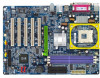
English GA-8SG800/GA-8S648FX Motherboard Layout KB_MS USB CPU_FAN ATX COMA LPT COMB MIC_IN LINE_OUT LINE_IN GAME CD_IN SOC KET478 IDE2 IDE1 A TX_12V DDR1 DDR2 DDR3 F_AU DIO AU X_IN N B_FAN SiS 648**/SiS 648FX* IT8705 AGP CI PCI1 SUR_CEN C ODEC 1 39 4 PCI2 BIOS P4 Titan PCI3 PCI4 - Gigabyte GA-8S648FXP-RZ | User Manual - Page 12
1- Install the Central Processing Unit (CPU) Step 2- Install memory modules Step 3- Install expansion cards Step 4- Connect ribbon cables, cabinet wires, and power supply Step 5- Setup BIOS software Step 6- Install supporting software tools Step 4 Step 1 Step 2 Step 4 Step 4 Step - Gigabyte GA-8S648FXP-RZ | User Manual - Page 13
look for a (golden) cut edge on the CPU upper corner. Then insert the CPU into the socket. M Please make sure the CPU type is supported by the motherboard. M If you do not match the CPU socket Pin 1 and CPU cut edge well, it will cause improper installation. Please change the insert orientation - Gigabyte GA-8S648FXP-RZ | User Manual - Page 14
try to remove the cooling fan, you might pull the processor out of the CPU socket alone with the cooling fan, and might damage the processor. To avoid this from happening Please refer to CPU cooling fan user's manual for more detail installation procedure. GA-8SG800/GA-8S648FX M otherboard - 10 - - Gigabyte GA-8S648FXP-RZ | User Manual - Page 15
motherboard has 3 dual inline memory module (DIMM) sockets. The BIOS will automatically detects memory type and size. To install the memory module, just push it vertically into the DIMM socket Status Supported Supported Not Supported Supported Supported Supported Supported Supported Supported DDR - Gigabyte GA-8S648FXP-RZ | User Manual - Page 16
instruction documentbefore installthe expansion card into the computer. 2. Remove your computer's chassis cover, necessaryscrews and slotbracketfrom the computer. 3. Press the expansion card firmly into expansion slotin motherboard BIOS utility of expansion card from BIOS. 8. Install related driver - Gigabyte GA-8S648FXP-RZ | User Manual - Page 17
Keyboard and PS/2 Mouse Connector PS/2 Mouse Connector (6pin Female) ØThis connector supports standard PS/2 keyboard and PS/2 mouse. PS/2 Keyboard Connector (6pin Female) please contact OS vendor for possible patch or driver upgrade.Formoreinformation pleasecontactyour OS or device(s) vendors. - Gigabyte GA-8S648FXP-RZ | User Manual - Page 18
pin Male) x Game /MIDI Ports ØThis connector supports joystick, MIDI keyboard and otherrelate audio devices. Joystick/ and Subwoofer) Line In (Rear Speaker) Ø After install onboard audio driver, you may connect speaker to Line Out jack, micro phone to MIC GA-8SG800/GA-8S648FX M otherboard - 14 - - Gigabyte GA-8S648FXP-RZ | User Manual - Page 19
English Step 4-2: Connectors Introduction 4 1 11 13 14 12 17 3 1) CPU_FAN 2) SYS_FAN 3) NB_FAN 4) ATX_12V 5) ATX 6) IDE1/IDE2 7) FDD 8) PWR_LED 9) F_PANEL 5 6 18 10 7 9 15 2 16 8 10) BAT 11) F_AUDIO 12) SUR_CEN 13) CD_IN 14) AUX_IN 15) SPDIF 16) F_USB1/F_USB2 17) 1394 18) CI - 15 - - Gigabyte GA-8S648FXP-RZ | User Manual - Page 20
to prevent the CPU from running under abnormal condition or damaged byoverheating.The CPU fan connector supports Max. current up to 600 mA. Ø This connector allows you to link with the ). Ifthis " ATX_12V connector" is notconnected, system cannot boot. GA-8SG800/GA-8S648FX M otherboard - 16 - - Gigabyte GA-8S648FXP-RZ | User Manual - Page 21
English 5) ATX(ATX Power) 20 Ø ACpower cord should only be connected to yourpower supply unitafterATX power cable and otherrelated devices are firmlyconnected to themainboard. +12V 5V SB (Stand by +5V) Power Good GND VCC GND VCC GND 3.3V 3.3V 1 VCC VCC -5V GND GND GND PS-ON(Soft On/Off) GND -12V - Gigabyte GA-8S648FXP-RZ | User Manual - Page 22
(+) Pin 2: LED cathode(-) NC Ø Please connectthe power LED, PC speaker, resetswitch and power switch etc ofyour chassis frontpanelto the F_PANELconnector according to the pin assignmentabove. GA-8SG800/GA-8S648FX M otherboard - 18 - - Gigabyte GA-8S648FXP-RZ | User Manual - Page 23
the pin assigmenton thecable is the sameas the pin assigmenton the MB header. To find out ifthe chassis you are buying supportfrontaudio connector,pleasecontactyourdealer.Pleasenote, you can have the alternative ofusing frontaudio connectororofusing rearaudio connectorto play sound. 12) SUR_CEN - Gigabyte GA-8S648FXP-RZ | User Manual - Page 24
D3 D7 D5 Please Note: Serial interface standard set by Institute ofElectricaland Electronics Engineers, which has features like high speed, high bandwidth and hot plug. GA-8SG800/GA-8S648FX M otherboard - 20 - - Gigabyte GA-8S648FXP-RZ | User Manual - Page 25
English 18) CI (CASE OPEN) 1 Signal GND Ø This 2 pin connector allows your system to enable or disable the "Case Open"item in BIOS if the system case begin remove. - 21 - Hardware Installation Process - Gigabyte GA-8S648FXP-RZ | User Manual - Page 26
English GA-8SG800/GA-8S648FX M otherboard - 22 - - Gigabyte GA-8S648FXP-RZ | User Manual - Page 27
ed Restore the previous CMOS value from CMOS, only for Option Page Setup Menu Load the file-safe default CMOS value from BIOS default table Load the Optimized Defaults Q-Flash function System Information Save all the CMOS changes, only for Main Menu - 23 - Gigabyte GA-8S648FXP-RZ | User Manual - Page 28
p lease press "Ctrl+F1" to search th e advanced optio n widden. l Standard CMOS Features This setup page includes all the items in standard compatible BIOS. l Advanced BIOS Features This setup page includes all the items of Award special enhanced features. GA-8SG800/GA-8S648FX Motherboard - 24 - - Gigabyte GA-8S648FXP-RZ | User Manual - Page 29
system. l Save & Exit Setup Save CMOS value settings to CMOS and exit setup. l Exit Without Saving Abandon all CMOS value changes and exit setup. - 25 - BIOS Setup - Gigabyte GA-8S648FXP-RZ | User Manual - Page 30
ear Sun. to Sat. Driv e A Driv e B Floppy 3 Mode Support Halt On Base Memory Ex tended Memory Total Memory 1.44M, 3.5 in. None Disabled All , . 8Week The w eek, from Sun to Sat, determined by the BIOS and is display only 8Month 8Day 8Year The month, Jan. Through Dec. The day - Gigabyte GA-8S648FXP-RZ | User Manual - Page 31
to F that has been installed in the computer. There are two types: auto type, and manual type. Manual type is user-definable; Auto type which will automatically detect HDD type. Note that the specifications . 82.88M, 3.5 in. 3.5 inch double-sided driv e; 2.88M by te capacity . - 27 - BIOS Setup - Gigabyte GA-8S648FXP-RZ | User Manual - Page 32
English C Floppy 3 Mode Support (for J apan Area) 8Disabled Normal Floppy Driv e. motherboard. Extended Memory The BIOS determines how much extended memory is present during the POST. This is the amount of memory located above 1 MB in the CPU's memory address map. GA-8SG800/GA-8S648FX Motherboard - Gigabyte GA-8S648FXP-RZ | User Manual - Page 33
:Prev ious Values F6:Fail-Safe Defaults F7:Optimized Defaults Figure 3: Adv anced BIOS Features " # " Sy stem w ill detect automatically and show up w hen Setup", and the option, "USB Legacy support" (in the "Integrated peripherals"), w ill not be prov ided to support. C First / S econd / Third - Gigabyte GA-8S648FXP-RZ | User Manual - Page 34
Fl oppy Seek During POST, BIOS will determine the floppy disk drive BIOS searches for floppy disk driv e to determine it is 40 or 80 tracks. Note that BIOS can not tell from 720 K, 1.2 M or 1.44 M driv e ty pe as they are all 80tracks. 8Disabled BIOS supported the 8X mode supported by the AGP - Gigabyte GA-8S648FXP-RZ | User Manual - Page 35
el u On-Chip Primary PCI IDE On-Chip Secondary PCI IDE AC97 Audio USB Controller USB Legacy Support Onboard Serial Port 1 Onboard Serial Port 2 Onboard Parallel Port Parallel Port Mode x ECP Mode Use DMA Fail-Safe Defaults F7:Optimized Defaults Figure 4: Integrated Peripherals - 31 - BIOS Setup - Gigabyte GA-8S648FXP-RZ | User Manual - Page 36
Will be automatically detected by BIOS. (Default Value) 8ATA66/100 Support When USB keyboard or mouse is installed, please set at Enabled. 8Enabled Enabled USB key board or mouse support. 8Disabled Disabled USB key board or mouse support. (Default v alue) GA-8SG800/GA-8S648FX Motherboard - Gigabyte GA-8S648FXP-RZ | User Manual - Page 37
address is 3E8. 82E8/IRQ3 Enable onboard Serial port 1 and address is 2E8. 8Disabled Disable onboard Serial port 1. C Onboard Serial Port 2 8Auto BIOS w ill automatically setup the port 2 address. 83F8/IRQ4 Enable onboard Serial port 2 and address is 3F8. 82F8/IRQ3 Enable onboard Serial port - Gigabyte GA-8S648FXP-RZ | User Manual - Page 38
330.(Default Value) 8Disabled Disable this function. CMidi Port IRQ 85 Set Midi Port IRQ to 5. 810 Set Midi Port IRQ to 10. (Default Value) GA-8SG800/GA-8S648FX Motherboard - 34 - - Gigabyte GA-8S648FXP-RZ | User Manual - Page 39
be in "Off" state. (Default Value) 8On When AC-pow er back to the sy stem, the sy stem w ill be in "On" state. - 35 - BIOS Setup - Gigabyte GA-8S648FXP-RZ | User Manual - Page 40
(S3): a. If use single color LED, pow er LED w ill turn off. b. If use dual color LED, pow er LED w ill turn to another color. GA-8SG800/GA-8S648FX Motherboard - 36 - - Gigabyte GA-8S648FXP-RZ | User Manual - Page 41
Assignment 8Auto Auto assign IRQ to PCI 3. (Default v alue) 83,4,5,7,9,10,11,12,14,15 Set IRQ 3,4,5,7,9,10,11,12,14,15 to PCI 3. - 37 - BIOS Setup - Gigabyte GA-8S648FXP-RZ | User Manual - Page 42
Open Status" to "Enabled" and sav e CMOS, y our computer w ill restart. Current Voltage (V) VCORE / VCC18 / +3.3V / +5V / +12V 8Detec t sy stem' s v oltage status automatic ally . GA-8SG800/GA-8S648FX Motherboard - 38 - - Gigabyte GA-8S648FXP-RZ | User Manual - Page 43
w hen FAN s tops. SYSTEM FAN Fail Warning Disa bled Fan Warning function disable. (Default v alue) Enab led Enalbe FAN w arning alarm w hen FAN s tops. - 39 - BIOS Setup - Gigabyte GA-8S648FXP-RZ | User Manual - Page 44
(MHz) 8100~355 Select CPU Clock to 100MHz~355MHz. Incorrect using it may cause y our sy stem broken. For pow er End-User use only ! GA-8SG800/GA-8S648FX Motherboard - 40 - - Gigabyte GA-8S648FXP-RZ | User Manual - Page 45
Control 8AUTO Set AGP/PCI Clock Control to AUTO. (Default v alue) 8Manual Set AGP/PCI Clock Control to Manual. C AGP Clock (MHz) 8Please set AGP Clock according to y our requirement. Incorrect using it may cause Control to +7.5%. 8+10% Set CPU Voltage Control to +10%. - 41 - BIOS Setup - Gigabyte GA-8S648FXP-RZ | User Manual - Page 46
Softw are }Standard CMOS Features Top Performance }Adv anced BIOS Features Load Fail-Safe Defaults }Integrated PeripThoepralPserformance Load Optimized must check whether your RAM, CPU support over clock when you set "Top Performance" to "Enabled". GA-8SG800/GA-8S648FX Motherboard - 42 - - Gigabyte GA-8S648FXP-RZ | User Manual - Page 47
Load Fail-Safe Defaults CMOS Setup Utility -Copy right (C) 1984-2002 Aw ard Softw are }Standard CMOS Features Top Performance }Adv anced BIOS Features Load Fail-Safe Defaults }Integrated Peripherals Load Optimized Defaults }Pow er Management SLeotuapd Fail-Safe DefauSletst?Su(pYe/rNv)is?oYr - Gigabyte GA-8S648FXP-RZ | User Manual - Page 48
ard Softw are }Standard CMOS Features Top Performance }Adv anced BIOS Features Load Fail-Safe Defaults }Integrated Peripherals Load Optimized Defaults } loads the factory defaults for BIOS and Chipset Features which the system automatically detects. GA-8SG800/GA-8S648FX Motherboard - 44 - - Gigabyte GA-8S648FXP-RZ | User Manual - Page 49
the system will boot and you can enter Setup freely. The BIOS Setup program allows you to specify two separate passwords: SUPERVISOR basic items. If y ou select "System" at "Password Check" in A dvance BIOS Features Menu, you will be prompted for the password every time the system is rebooted - Gigabyte GA-8S648FXP-RZ | User Manual - Page 50
(C) 1984-2002 Aw ard Softw are }Standard CMOS Features Top Performance }Adv anced BIOS Features Load Fail-Safe Defaults }Integrated Peripherals Load Optimized Defaults }Pow er Management Setup value to RTC CMOS. Type "N" will return to Setup Utility. GA-8SG800/GA-8S648FX Motherboard - 46 - - Gigabyte GA-8S648FXP-RZ | User Manual - Page 51
English Exit Without Saving CMOS Setup Utility -Copy right (C) 1984-2002 Aw ard Softw are }Standard CMOS Features Top Performance }Adv anced BIOS Features Load Fail-Safe Defaults }Integrated Peripherals Load Optimized Defaults }Pow er Management Setup Set Superv isor Passw ord }PnP/PCI - Gigabyte GA-8S648FXP-RZ | User Manual - Page 52
English GA-8SG800/GA-8S648FX Motherboard - 48 - - Gigabyte GA-8S648FXP-RZ | User Manual - Page 53
/8X AGPCLK (66M Hz) 5 PCI Pentium 4 Socket 478 CPU CPUCLK+/- (100/133/200*MHz) System Bus CICL K (33M Hz) MIC LINE-IN LINE-OUT AC97 Link SiS 963 BIOS LPC BUS IT8705 AC97 CODEC 24 MHz 6 USB ATA33/66/100/133 33 133MHz) "*" For GA-8S648FX only "**" For GA-8SG800 only - 49 - Technical Reference - Gigabyte GA-8S648FXP-RZ | User Manual - Page 54
it costs? Impossible! It's free! Now, ifyou buy a Gigabyte's motherboard, you could find this amazing software in the attached driver CD. But please remember,connected to internetat first,then you could have a internetBIOS update from your Gigabyte @BIOS. GA-8SG800/GA-8S648FX M otherboard - 50 - - Gigabyte GA-8S648FXP-RZ | User Manual - Page 55
,try and use manydifferenthardware or BIOS tools to do "Overclock". Gigabyte motherboard attached in driver CD. Users may make a test drive of "EasyTune 4" to find out more amazing features by themselves. *Some Gigabyte products are notfullysupported byEasyTune 4. Please find the products supported - Gigabyte GA-8S648FXP-RZ | User Manual - Page 56
is a pre-O.S. BIOS flash utility enables users to update its BIOS within BIOS mode, no more Test) it will allow you to enter AWARD BIOS CMOS SETUP, then press to enter Performance }Advanced BIOS Features Load Fail BIOS from Floppy Save BIOS to Floppy Enter: Run SpaceBar:Change Value ESC: - Gigabyte GA-8S648FXP-RZ | User Manual - Page 57
: 1.14M DEL: Delete ESC: Return Main Where XXXX.XX is name of the BIOS file. !Press Enter to Run. Are you sure to update BIOS? [Enter] to contiune Or [ESC] ot abort... !Press Enter to Run. !! COPY BIOS Completed -Pass !! Please press any keyto continue Congratulation!You have completed the - Gigabyte GA-8S648FXP-RZ | User Manual - Page 58
English Method 2: BIOS Flash Utility BIOS Flash Procedure We use GA-7VTXmotherboard and Flash841 BIOS flash utility as example. Please flash the BIOS according to the following procedures ifyou are now under the DOS mode. Flash BIOSProcedure: STEP 1: (1) Please make sure your system has installed - Gigabyte GA-8S648FXP-RZ | User Manual - Page 59
English (2) Selectthe "Quick (erase)" for FormatType,and pick both "Displaysummary when finished" and "Copy system files", after thatpress "Start". That will formatthe floppyand transfer the needed system files to it. Beware: This procedure will erase all the prior data on that floppy, so please - Gigabyte GA-8S648FXP-RZ | User Manual - Page 60
English STEP 3: Download BIOS and BIOS utility program. (1) Please go to Gigabyte website http://www.gigabyte.com.tw/index.html, and click "Support". (2) From Supportzone, click the "Motherboards BIOS & Drivers". GA-8SG800/GA-8S648FX M otherboard - 56 - - Gigabyte GA-8S648FXP-RZ | User Manual - Page 61
English (3) We use GA-7VTXmotherboard as example.Please selectGA-7VTX by Modelor Chipsetoptional menu to obtain BIOS flash files. (4) Selectan appropriate BIOS version (For example: F4), and click to download the file. Itwill pop up a file download screen, then selectthe "Open this file from its - Gigabyte GA-8S648FXP-RZ | User Manual - Page 62
English (5) Atthis time the screen shows the following picture, please click "Extract" button to unzip the files. (6) Please extract the download files into the clean bootable floppy disk A mentioned in STEP 2,and press "Extract". GA-8SG800/GA-8S648FX M otherboard - 58 - - Gigabyte GA-8S648FXP-RZ | User Manual - Page 63
,restart the system. The system will boot from the floppy disk. Please press keyto enter BIOS setup main menu when system is bootup. Ame r ican R e le a se :0 9 /1 6 /9 9 Meg a tre n d s AMIBIOS ( C) 19 9 9 Ame ri ca n Me ga tr en d 7 VTX F1 Ch eck Syste m Hea lth OK AMD- Ath lo n( tm) Pr - Gigabyte GA-8S648FXP-RZ | User Manual - Page 64
to select "Floppy". AMIBIOS SETUP - BIOS FEATURES SETUP ( C ) 2001 American : Old Values (Shift)F2: Color F6 : Load BIOS Defaults F7 : Load Setup Defaults (4) Press "ESC" reboot automatically, the new BIOS setting will be taken effectnextboot PERIPHERALS BIOS DETECTION LOAD BIOS DEFAULTS SAVE - Gigabyte GA-8S648FXP-RZ | User Manual - Page 65
After the system boot from floppy disk, type "A:\> dir/w" and press "Enter" to check the entire files in floppy A. Then type the "BIOS flash utility" and "BIOS file" after A:\>. In this case you have to type "A:\> Flash841 7VTX.F4" and then press "Enter". StartingWindows 98... Microsoft(R) Windows98 - Gigabyte GA-8S648FXP-RZ | User Manual - Page 66
. It will render your BIOS corrupted and system totally inoperative. Are you sure to flash the BIOS? [Enter] to continue Or [Esc] to cancel? (4) The BIOS flash completed. Please press [ESC] to exit Flash Utility. EXIT? [Enter] to continue Or [Esc] to cancel? GA-8SG800/GA-8S648FX M otherboard - 62 - Gigabyte GA-8S648FXP-RZ | User Manual - Page 67
screen will indicate your motherboard model and currentBIOSversion. Ame r ican R e le a se :0 9 /1 6 /9 9 Meg a tre n d s AMIBIOS ( C) 19 9 9 Ame ri ca n Me ga tr en d 7 CONFIGURATIONLoad Setup DefaultsI?DE(YH/DND)?ANUTO DETECTION LOAD BIOS DEFAULTS SAVE & EXIT SETUP LOAD SETUP DEFAULTS EXIT - Gigabyte GA-8S648FXP-RZ | User Manual - Page 68
EXIT WITHOUT SAVING ESC: Quit hifg : Select Item (Shift)F2 : Change Color F5: Old Values F6: Load BIOS Defaults F7: Load Setup Defaults F10:Save & Exit Save Data to CM OS & Exit SETUP (4) Congratulate you have accomplished the BIOS flash procedure. GA-8SG800/GA-8S648FX M otherboard - 64 - - Gigabyte GA-8S648FXP-RZ | User Manual - Page 69
If you don't have DOS boot disk, we recommend thatyou used Gigabyte @BIOSTM program to flash BIOS. Press here. 1.Click "@BIOS" 2.Click"Start"-"Programs"" GIG ABYTE"- " @BIOS" (1) (2) 3.Click "P". 4.Click here. 5. Please select @BIOS sever site, then Click "OK". (3) (4) Methods and steps - Gigabyte GA-8S648FXP-RZ | User Manual - Page 70
your motherboard's. Otherwise, your system won'tboot. c. In method I, if the BIOS file you need cannotbe found in @BIOSTM server, please go onto Gigabyte's web site fordownloading and updating itaccording to method II. d. Please note thatanyinterruption during updating willcause system unbooted GA - Gigabyte GA-8S648FXP-RZ | User Manual - Page 71
effect if the stereo output is applied. STEP 1: Connect the stereo speakers or earphone to "Line Out". Line Out STEP 2 : After installation of the audio driver, you'll find an icon on the taskbar's status area. Click the audio icon "Sound Effect" from the windows tray at the bottom of the - Gigabyte GA-8S648FXP-RZ | User Manual - Page 72
to "Line Out", the rear channels to "Line In". STEP 2 : After installation of the audio driver, you'll find an icon on the taskbar's status area. Click the audio icon "Sound Effect" Please select the other settings for 4 channels output. GA-8SG800/GA-8S648FX M otherboard - 68 - Line Out Line In - Gigabyte GA-8S648FXP-RZ | User Manual - Page 73
front channels to "Line Out",the rear channels to "Line In", and the Center/Subwoofer channels to "MIC In". STEP 2 : After installation of the audio driver, you'll find an icon on the taskbar's status area. Click the audio icon "Sound Effect" from the windows tray at the bottom of the - Gigabyte GA-8S648FXP-RZ | User Manual - Page 74
channels. It is the best solution if you need 6 channel output, Line In and MIC at the same time. "SURROUND-KIT" is included in the GIGABYTE unique "Audio Com bo Kit" as picture. STEP 1 : Insert the "SURROUND-KIT" in the back of the case ,and fix it with the screw. STEP - Gigabyte GA-8S648FXP-RZ | User Manual - Page 75
English STEP 3 : Connect the front channels to back audio panel's "Line Out", the rear channels to SURROUND-KIT's REAR R/L, and the Center/Subwoofer channels to SURROUND-KIT's SUB CENTER. STEP 4 : Click the audio icon "Sound Effect" from the windows tray at the bottom of the screen. STEP 5 : Select - Gigabyte GA-8S648FXP-RZ | User Manual - Page 76
SPDIF Output Device (Optional Device) A "SPDIF output" device is available on the motherboard. Cable with rear bracket is provided and could link to the "SPDIF output" 2. Connect SPDIF device to the m otherboard. 3. Connect SPDIF to the SPDIF decoder. GA-8SG800/GA-8S648FX M otherboard - 72 - - Gigabyte GA-8S648FXP-RZ | User Manual - Page 77
- 73 - Technical Reference English - Gigabyte GA-8S648FXP-RZ | User Manual - Page 78
English GA-8SG800/GA-8S648FX M otherboard - 74 - - Gigabyte GA-8S648FXP-RZ | User Manual - Page 79
2.2) Insert the driver CD-title that came with your motherboard into your CD-ROM drive, the driver CD-title will auto start and show the installation guide. If not, to install the driver manually or switch to the to install the drivers automatically. Massage: Some device drivers will restart your - Gigabyte GA-8S648FXP-RZ | User Manual - Page 80
Please also note that Microsoft® USB2.0 driver is currently supported by Windows XP and Windows 2000 only. Once we get the latest SiS® USB2.0 driver for Windows 98 and Windows ME, we will put the driver on GIGABYTE website asap. (http://www.gigabyte.com.tw). GA-8SG800/GA-8S648FX Motherboard - 76 - - Gigabyte GA-8S648FXP-RZ | User Manual - Page 81
based utility which is used to browse the DMI/SMBIOS information of the system. n Face-Wizard New utility for adding BIOS logo. n @BIOS Gigabyte windows flash BIOS utility. n Acrobat e-Book Useful utility from Adobe. n AcrobatReader Popular utility from Adobe for reading .PDF file format documents - Gigabyte GA-8S648FXP-RZ | User Manual - Page 82
English SOFTWARE INFORMATION This page list the contects of softwares and drivers in this CD title. HARDWARE INFORMATION This page lists all device you have for this motherboard. CONTACT US Please see the last page for details. GA-8SG800/GA-8S648FX Motherboard - 78 - - Gigabyte GA-8S648FXP-RZ | User Manual - Page 83
disk before installing drivers. You also need to go through some rather different steps in the installation process. Therefore, we suggest that you refer to the installation steps in the RAID manual at our website. (Please download it at http://tw.giga-byte.com/support/user_pdf/raid_manual.pdf - Gigabyte GA-8S648FXP-RZ | User Manual - Page 84
do I disable onboard VGA card in order to add an external VGA card? Answer: Gigabyte motherboards will auto-detect the external VGA card after it is plugged in, so you don't need to change any setting manually to disable the onboard VGA. Question 9: Why cannot I use the IDE 2? Answer: Please refer - Gigabyte GA-8S648FXP-RZ | User Manual - Page 85
usually stand for? Answer: The beep codes below may help you identify the possible computer problems. However, they are only for reference purposes. The situations might differ from case to case. gAMI BIOS Beep Codes *Computer gives 1 short beep when system boots successfully. *Except for beep code - Gigabyte GA-8S648FXP-RZ | User Manual - Page 86
trouble during boot up, please follow the troubleshooting procedures . START Turn off the power and unplug the AC power cable, then remove all of the add-on cards and cables from motherboard. Please make sure motherboard cable and turn on the system. A GA-8SG800/GA-8S648FX Motherboard - 82 - - Gigabyte GA-8S648FXP-RZ | User Manual - Page 87
If the above procedure unable to solve your problem, please contact with your local retailer or national distributor for help. Or, you could submit your question to the service mail via Gigabyte website technical support zone (http://www.gigabyte.com.tw). The appropriate response will be provided - Gigabyte GA-8S648FXP-RZ | User Manual - Page 88
English & Technical Support/RMA Sheet Customer/Country: Contact Person: Company: E-mail Add. : Model name/Lot Number: BIOS version: O.S./A.S.: Hardware Mfs. name Phone No.: PCB revision: Size: Driver/Utility: Problem Description: & GA-8SG800/GA-8S648FX Motherboard - 84 - - Gigabyte GA-8S648FXP-RZ | User Manual - Page 89
English Acronyms Acronyms ACPI APM AGP AMR ACR BIOS CPU CMOS CRIMM CNR DMA DMI DIMM DRM DRAM DDR ECP ESCD ECC EMC EPP ESD FDD FSB HDD IDE IRQ Meaning Advanced Configuration and - Gigabyte GA-8S648FXP-RZ | User Manual - Page 90
Card Operating System Original Equipment Manufacturer PCI A.G.P. Controller Power-On Self Test Peripheral Component Interconnect Rambus in-line Memory Module Special Circumstance Instructions Single Edge Contact Cartridge Static Random Access Memory GA-8SG800/GA-8S648FX Motherboard - 86 - - Gigabyte GA-8S648FXP-RZ | User Manual - Page 91
- 87 - Memo English - Gigabyte GA-8S648FXP-RZ | User Manual - Page 92
English GA-8SG800/GA-8S648FX Motherboard - 88 - - Gigabyte GA-8S648FXP-RZ | User Manual - Page 93
- 89 - Memo English - Gigabyte GA-8S648FXP-RZ | User Manual - Page 94
English GA-8SG800/GA-8S648FX Motherboard - 90 - - Gigabyte GA-8S648FXP-RZ | User Manual - Page 95
- 91 - Memo English - Gigabyte GA-8S648FXP-RZ | User Manual - Page 96
: www.gigabyte.com.cn Beijing Office Tel:86-10-82856054 86-10-82856064 86-10-82856094 Fax: 86-10-82856575 Web Address: www.gigabyte.com.cn E-mail:[email protected] Chengdu Office Tel: 86-28-85236930 Fax: 86-28-85256822 Web Address: www.gigabyte.com.cn GA-8SG800/GA-8S648FX Motherboard - 92
-
 1
1 -
 2
2 -
 3
3 -
 4
4 -
 5
5 -
 6
6 -
 7
7 -
8
-
9
-
10
-
11
-
12
-
13
-
14
-
15
-
16
-
17
-
18
-
19
-
20
-
21
-
22
-
23
-
24
-
25
-
26
-
27
-
28
-
29
-
30
-
31
-
32
-
33
-
34
-
35
-
36
-
37
-
38
-
39
-
40
-
41
-
42
-
43
-
44
-
45
-
46
-
47
-
48
-
49
-
50
-
51
-
52
-
53
-
54
-
55
-
56
-
57
-
58
-
59
-
60
-
61
-
62
-
63
-
64
-
65
-
66
-
67
-
68
-
69
-
70
-
71
-
72
-
73
-
74
-
75
-
76
-
77
-
78
-
79
-
80
-
81
-
82
-
83
-
84
-
85
-
86
-
87
-
88
-
89
-
90
-
91
-
92
-
93
-
94
-
95
-
96
 |
 |

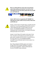
When you installing AGP card, please make sure the following
notice is fully understood and practiced. If your AGP card has
"AGP 4X/8X(1.5V) notch"(show below), please make sure your AGP
card is AGP 4X/8X(1.5V).
Caution: AGP 2X card is not supported by SiS
®
648/648FX. You
might experience system unable to boot up normally. Please insert
an AGP 4X/8X card.
Example 1: Diamond Vipper V770 golden finger is compatible with 2X/4X
mode AGP slot. It can be switched between AGP 2X(3.3V) or 4X(1.5V)
mode by adjusting the jumper. The factory default for this card is
2X(3.3V). The GA-8SG800/GA-8S648FX (or any AGP 4X only)
motherboards might not function properly, if you install this card without
switching the jumper to 4X(1.5) mode in it.
Example 2: Some ATi Rage 128 Pro graphics cards made by "Power
Color", the graphics card manufacturer & some SiS 305 cards, their
golden finger is compatible with 2X(3.3V)/4X(1.5V) mode AGP slot, but
they support 2X(3.3V) only. The GA-8SG800/GA-8S648FX
(or any AGP 4X only) motherboards might not function properly, If you
install this card in it.
Note : Although Gigabyte's AG32S(G) graphics card is based on
ATi Rage 128 Pro chip, the design of AG32S(G) is compliance
with AGP 4X(1.5V) specification. Therefore, AG32S (G)will work
fine with SiS
®
648/648FX based motherboards.
AGP 4X/8X notch